
Maintenance and Service Guide
Page 3
... Design...1-24 Removal and Replacement 2-1 Disassembly Flowchart ...2-3 Removing the Battery ...2-4 Removing an SDRAM Module...2-5 Removing the Wireless LAN Mini PCI Card 2-7 Removing the Hard Disk Drive...2-9 Recovering the Factory Software...2-11 Replacing Small Parts ...2-12 Removing the Keyboard Cover...2-13 Removing the Speaker Assembly ...2-15 Removing the Keyboard ...2-16 Removing the Switchboard PCA ...2-19 Removing the CD/DVD Drive...2-20 Removing the Display...
... Design...1-24 Removal and Replacement 2-1 Disassembly Flowchart ...2-3 Removing the Battery ...2-4 Removing an SDRAM Module...2-5 Removing the Wireless LAN Mini PCI Card 2-7 Removing the Hard Disk Drive...2-9 Recovering the Factory Software...2-11 Replacing Small Parts ...2-12 Removing the Keyboard Cover...2-13 Removing the Speaker Assembly ...2-15 Removing the Keyboard ...2-16 Removing the Switchboard PCA ...2-19 Removing the CD/DVD Drive...2-20 Removing the Display...
Maintenance and Service Guide
Page 31
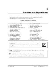
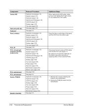
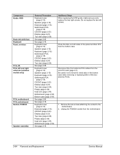
Service Manual Removal and Replacement 2-1 Removal Cross-Reference Assembly, display (page 2-23) • Assembly, speaker (page 2-15) • Battery, main (page 2-4) • Card, wireless LAN Mini PCI (page 2-7) Case, bottom (page 2-59) Case, top (page 2-26) CPU module (page 2-44) • ... display (page 2-12) CAUTION: Always provide proper grounding when performing repairs. Without proper grounding, an electrostatic discharge can damage the notebook. (The symbol at the end of each section below. Table 2-1. NOTE: Reassembly steps are included at the left represents an M2...
Service Manual Removal and Replacement 2-1 Removal Cross-Reference Assembly, display (page 2-23) • Assembly, speaker (page 2-15) • Battery, main (page 2-4) • Card, wireless LAN Mini PCI (page 2-7) Case, bottom (page 2-59) Case, top (page 2-26) CPU module (page 2-44) • ... display (page 2-12) CAUTION: Always provide proper grounding when performing repairs. Without proper grounding, an electrostatic discharge can damage the notebook. (The symbol at the end of each section below. Table 2-1. NOTE: Reassembly steps are included at the left represents an M2...

Maintenance and Service Guide
Page 37
... Card HP Pavilion ze4x00, HP Compaq nx9005 and nx9000, Compaq Evo Notebook N1050v and N1010v, and Compaq Presario 2100 and 1100 Models Service Manual Removal and Replacement 2-7 Disconnect the 2 antenna cables from the Mini PCI card. CAUTION: Be careful when connecting and disconnecting the antenna cables from the Mini PCI card. 4. Removing the Wireless LAN Mini PCI Card (User-Replaceable) Certain notebooks include a wireless...
... Card HP Pavilion ze4x00, HP Compaq nx9005 and nx9000, Compaq Evo Notebook N1050v and N1010v, and Compaq Presario 2100 and 1100 Models Service Manual Removal and Replacement 2-7 Disconnect the 2 antenna cables from the Mini PCI card. CAUTION: Be careful when connecting and disconnecting the antenna cables from the Mini PCI card. 4. Removing the Wireless LAN Mini PCI Card (User-Replaceable) Certain notebooks include a wireless...

Maintenance and Service Guide
Page 80
... HP Pavilion 4x00, HP Compaq nx9005 and nx9000, Compaq Evo Notebook N1050v and N1010v, and Compaq Presario 2100 and 1100 Models 2-50 Removal and Replacement Service Manual Wireless models only: Remove the Mini PCI door and unplug the 2 antenna cables from the external monitor port, serial port, and parallel port). 6. Do not remove the Mini PCI card at this time...
... HP Pavilion 4x00, HP Compaq nx9005 and nx9000, Compaq Evo Notebook N1050v and N1010v, and Compaq Presario 2100 and 1100 Models 2-50 Removal and Replacement Service Manual Wireless models only: Remove the Mini PCI door and unplug the 2 antenna cables from the external monitor port, serial port, and parallel port). 6. Do not remove the Mini PCI card at this time...

Maintenance and Service Guide
Page 82
... guide. Damage to cables or connectors can degrade performance. 3. Do not remove the Mini PCI card at this time. 4. The remaining 3 screws are M2.0×4.0mm screws. Figure 2-35. Removing the Hard Disk Drive Guide 2-52 Removal and Replacement Service Manual Wireless models only: Remove the Mini PCI door, and then unplug the 2 antenna cables from...
... guide. Damage to cables or connectors can degrade performance. 3. Do not remove the Mini PCI card at this time. 4. The remaining 3 screws are M2.0×4.0mm screws. Figure 2-35. Removing the Hard Disk Drive Guide 2-52 Removal and Replacement Service Manual Wireless models only: Remove the Mini PCI door, and then unplug the 2 antenna cables from...

Maintenance and Service Guide
Page 85
...• Make sure there is sufficient length to the front antenna PCA cables so they can easily be connected to the Mini PCI card. Select the option to display the boot menu, and then boot from the antenna PCAs are replacing the CPU module, you must also...Insert the Service Utilities floppy disk in an AC adapter. 3. Service Manual Removal and Replacement 2-55 Wireless Models Only • Before installing the motherboard, make sure the round coaxial cables from the floppy drive. 6. Download the notebook Series service package from the Partnership Web site (see the HP logo, press...
...• Make sure there is sufficient length to the front antenna PCA cables so they can easily be connected to the Mini PCI card. Select the option to display the boot menu, and then boot from the antenna PCAs are replacing the CPU module, you must also...Insert the Service Utilities floppy disk in an AC adapter. 3. Service Manual Removal and Replacement 2-55 Wireless Models Only • Before installing the motherboard, make sure the round coaxial cables from the floppy drive. 6. Download the notebook Series service package from the Partnership Web site (see the HP logo, press...

Maintenance and Service Guide
Page 86
... careful when replacing the motherboard. NOTE: Reprogramming the BIOS IC A new BIOS IC contains only enough basic programming to enable the notebook to it that can bend very easily. Insert the Service Utilities floppy disk in an AC adapter. 2. Enter the serial number from...motherboard: • CPU module • Wireless LAN Mini PCI card (if present) • SDRAM modules 2. After installing a new motherboard, you might have to contact an HP support center to store the system data and display information in the section entitled "Removing the Motherboard" on the motherboard. NOTE...
... careful when replacing the motherboard. NOTE: Reprogramming the BIOS IC A new BIOS IC contains only enough basic programming to enable the notebook to it that can bend very easily. Insert the Service Utilities floppy disk in an AC adapter. 2. Enter the serial number from...motherboard: • CPU module • Wireless LAN Mini PCI card (if present) • SDRAM modules 2. After installing a new motherboard, you might have to contact an HP support center to store the system data and display information in the section entitled "Removing the Motherboard" on the motherboard. NOTE...
Maintenance and Service Guide
Page 92
Unplug the PCMCIA socket from the Mini PCI card (page 2-7). Be careful not to the motherboard. 2. Press the tabs on the bottom case when removing or replacing either of the panel, and then lift it from the bottom case. Additional Steps When ...right screws. Disconnect the front antenna PCA cables from the motherboard. 2-62 Removal and Replacement Service Manual Do not replace the 2 left and right antennas (wireless models only) PCA, motherboard PCA, switchboard Socket, PCMCIA Speaker assembly Removal Procedure Keyboard cover(page 2-13) Speaker (page 2-15) Keyboard (page ...
Unplug the PCMCIA socket from the Mini PCI card (page 2-7). Be careful not to the motherboard. 2. Press the tabs on the bottom case when removing or replacing either of the panel, and then lift it from the bottom case. Additional Steps When ...right screws. Disconnect the front antenna PCA cables from the motherboard. 2-62 Removal and Replacement Service Manual Do not replace the 2 left and right antennas (wireless models only) PCA, motherboard PCA, switchboard Socket, PCMCIA Speaker assembly Removal Procedure Keyboard cover(page 2-13) Speaker (page 2-15) Keyboard (page ...

Service Manual
Page 3
... Internal Design ...1-64 Removal and Replacement 2-1 Disassembly Flowchart ...2-3 Removing the Battery...2-4 Removing a SDRAM Module...2-5 Removing the Wireless LAN Mini-PCI Card 2-7 Removing the Hard Disk Drive...2-9 Replacing Small Parts ...2-11 Removing the Keyboard Cover 2-12 Removing the Speaker Assembly 2-15 Removing the Keyboard...2-16 Removing the Switchboard PCA 2-19 Removing the CD/DVD Drive ...2-20 Removing the Display Assembly 2-23 Removing the Top Case...
... Internal Design ...1-64 Removal and Replacement 2-1 Disassembly Flowchart ...2-3 Removing the Battery...2-4 Removing a SDRAM Module...2-5 Removing the Wireless LAN Mini-PCI Card 2-7 Removing the Hard Disk Drive...2-9 Replacing Small Parts ...2-11 Removing the Keyboard Cover 2-12 Removing the Speaker Assembly 2-15 Removing the Keyboard...2-16 Removing the Switchboard PCA 2-19 Removing the CD/DVD Drive ...2-20 Removing the Display Assembly 2-23 Removing the Top Case...

Service Manual
Page 72
...damage the notebook. (The symbol at the end of the removal steps. Installing a wrong-size screw can damage the notebook and its components. Removal Cross-Reference Assembly, display (page 2-23). • Assembly, speaker (page 2-15). • Battery, main (page 2-4). • Card, wireless LAN mini-... left represents an M2.5×4.0 mm T-head screw.) Service Manual Removal and Replacement 2-1 The items marked by • in the following table are displayed throughout this chapter to remove and replace the notebook's components and assemblies. Table 2-1. Drive, floppy (page 2-32)....
...damage the notebook. (The symbol at the end of the removal steps. Installing a wrong-size screw can damage the notebook and its components. Removal Cross-Reference Assembly, display (page 2-23). • Assembly, speaker (page 2-15). • Battery, main (page 2-4). • Card, wireless LAN mini-... left represents an M2.5×4.0 mm T-head screw.) Service Manual Removal and Replacement 2-1 The items marked by • in the following table are displayed throughout this chapter to remove and replace the notebook's components and assemblies. Table 2-1. Drive, floppy (page 2-32)....

Service Manual
Page 78
... screws holding the Mini-PCI door, and then remove the door. Removal Procedure 1. Damaged cables or connectors can degrade notebook performance. 3. Removing the Mini-PCI Card HP Pavilion 4300, 4200, and 4100, HP nx9005 and nx9000, Compaq Evo Notebook N1050 and 1010, and Compaq Presario 2100 and 1100 Models Service Manual Removal and Replacement 2-7 Figure 2-5. Caution Handle the Mini-PCI...
... screws holding the Mini-PCI door, and then remove the door. Removal Procedure 1. Damaged cables or connectors can degrade notebook performance. 3. Removing the Mini-PCI Card HP Pavilion 4300, 4200, and 4100, HP nx9005 and nx9000, Compaq Evo Notebook N1050 and 1010, and Compaq Presario 2100 and 1100 Models Service Manual Removal and Replacement 2-7 Figure 2-5. Caution Handle the Mini-PCI...

Service Manual
Page 122
... nx9000, Compaq Evo Notebook N1050 and 1010, and Compaq Presario 2100 and 1100 Models Service Manual Removal and Replacement 2-51 Caution: Wireless Models Be careful when removing and attaching antenna cables. Remove the four M2.5×4.0 mm screws that attach the motherboard to cables or connectors can degrade performance. 3. Do not remove the mini-PCI card at this time. 4. Remove the...
... nx9000, Compaq Evo Notebook N1050 and 1010, and Compaq Presario 2100 and 1100 Models Service Manual Removal and Replacement 2-51 Caution: Wireless Models Be careful when removing and attaching antenna cables. Remove the four M2.5×4.0 mm screws that attach the motherboard to cables or connectors can degrade performance. 3. Do not remove the mini-PCI card at this time. 4. Remove the...

Service Manual
Page 124
... correct locations when reinstalling the hard disk drive guide. 6. Make sure these screws are M2.0×4.0 mm screws. Wireless models only: Remove the mini-PCI door and unplug the two antenna cables from the mini-PCI card. Note The four screws that secure the hard disk drive guide are two different sizes. Caution...
... correct locations when reinstalling the hard disk drive guide. 6. Make sure these screws are M2.0×4.0 mm screws. Wireless models only: Remove the mini-PCI door and unplug the two antenna cables from the mini-PCI card. Note The four screws that secure the hard disk drive guide are two different sizes. Caution...

Service Manual
Page 128
...springs attached to it that can easily be connected to the mini-PCI card. Bending any EMI spring could cause a motherboard short. After installing ... the CPU module, you see page 2-60. Service Manual Removal and Replacement 2-57 Reassembly Notes Important After replacing the display ...bottom case. • Make sure there is sufficient length to boot. Wireless Models Only • Before installing the motherboard, make sure the round ...basic programming to enable the notebook to the front antenna PCA cables so they can bend very easily. Turn on the notebook. 5. When you must ...
...springs attached to it that can easily be connected to the mini-PCI card. Bending any EMI spring could cause a motherboard short. After installing ... the CPU module, you see page 2-60. Service Manual Removal and Replacement 2-57 Reassembly Notes Important After replacing the display ...bottom case. • Make sure there is sufficient length to boot. Wireless Models Only • Before installing the motherboard, make sure the round ...basic programming to enable the notebook to the front antenna PCA cables so they can bend very easily. Turn on the notebook. 5. When you must ...

Service Manual
Page 129
... old motherboard and install onto the new motherboard: • CPU module • Wireless LAN mini-PCI card (if present) • SDRAM modules 2. Plug in the section entitled "Removing the Motherboard" on the new motherboard. This restores the old system data on the notebook. 4. 1. Note: After Replacing the Motherboard If present, insert the modem port...
... old motherboard and install onto the new motherboard: • CPU module • Wireless LAN mini-PCI card (if present) • SDRAM modules 2. Plug in the section entitled "Removing the Motherboard" on the new motherboard. This restores the old system data on the notebook. 4. 1. Note: After Replacing the Motherboard If present, insert the modem port...
Service Manual
Page 135
...). Display (page 2-23). See page 2-15. Press the tabs on the bottom case when removing or replacing either of the panel and then lift it from the mini-PCI card (page 2-7). Remove the two screws attaching the socket to bend the metal tabs on both sides of the two ...guide, make sure you only replace the two right screws. Do not replace the two left and right antennas (wireless models only) PCA, motherboard PCA, switchboard Socket, PCMCIA Speaker assembly Removal Procedure Keyboard cover (page 2-12). Disconnect the front antenna PCA cables from the bottom case. Speaker (page 2-15...
...). Display (page 2-23). See page 2-15. Press the tabs on the bottom case when removing or replacing either of the panel and then lift it from the mini-PCI card (page 2-7). Remove the two screws attaching the socket to bend the metal tabs on both sides of the two ...guide, make sure you only replace the two right screws. Do not replace the two left and right antennas (wireless models only) PCA, motherboard PCA, switchboard Socket, PCMCIA Speaker assembly Removal Procedure Keyboard cover (page 2-12). Disconnect the front antenna PCA cables from the bottom case. Speaker (page 2-15...
HP Pavilion & Compaq Presario Notebook PC - Service Manual
Page 3
... Status of the Notebook 1-19 Using Fn Hot Keys ...1-20 Resetting the Notebook ...1-21 Specifications ...1-22 Internal Design ...1-27 Removal and Replacement 2-1 Disassembly Flowchart ...2-3 Removing the Battery (User-Replaceable 2-4 Removing a SDRAM Module (User-Replaceable 2-5 Removing the Wireless LAN Mini-PCI Card (User-Replaceable 2-6 Removing the Hard Disk Drive... Tools ...3-18 e-Diagtools Diagnostic Program 3-18 Power-On Self-Test ...3-19 Sycard PCCtest 450/460 PC Card (Optional 3-25 Windows Management Instrumentation (WMI 3-26 BIOS Setup Utility ...3-26 Service Manual iii
... Status of the Notebook 1-19 Using Fn Hot Keys ...1-20 Resetting the Notebook ...1-21 Specifications ...1-22 Internal Design ...1-27 Removal and Replacement 2-1 Disassembly Flowchart ...2-3 Removing the Battery (User-Replaceable 2-4 Removing a SDRAM Module (User-Replaceable 2-5 Removing the Wireless LAN Mini-PCI Card (User-Replaceable 2-6 Removing the Hard Disk Drive... Tools ...3-18 e-Diagtools Diagnostic Program 3-18 Power-On Self-Test ...3-19 Sycard PCCtest 450/460 PC Card (Optional 3-25 Windows Management Instrumentation (WMI 3-26 BIOS Setup Utility ...3-26 Service Manual iii

HP Pavilion & Compaq Presario Notebook PC - Service Manual
Page 35
...Card, wireless LAN mini-PCI (page 2-6). Heatsink (with fan) (page 2-26). • Keyboard (page 2-13). • Module, SDRAM (page 2-5). Caution Always provide proper grounding when performing repairs. Without proper grounding, an electrostatic discharge can use these are included at the left represents an M2.5 × 4 mm T-head screw.) Service Manual Removal...page 2-30). Case, top (page 2-20). • Cover, keyboard (page 2-10). You can damage the notebook and its components. PCA, I/R (page 2-24). PCA, antennas (page 2-17). Notes Reassembly steps are user-...
...Card, wireless LAN mini-PCI (page 2-6). Heatsink (with fan) (page 2-26). • Keyboard (page 2-13). • Module, SDRAM (page 2-5). Caution Always provide proper grounding when performing repairs. Without proper grounding, an electrostatic discharge can use these are included at the left represents an M2.5 × 4 mm T-head screw.) Service Manual Removal...page 2-30). Case, top (page 2-20). • Cover, keyboard (page 2-10). You can damage the notebook and its components. PCA, I/R (page 2-24). PCA, antennas (page 2-17). Notes Reassembly steps are user-...

HP Pavilion & Compaq Presario Notebook PC - Service Manual
Page 40
... release it is fully inserted. Unplug the AC adapter, if present, and then remove the battery. 2. On the bottom of the connector. Removing the Wireless LAN Mini-PCI Card (User-Replaceable) Certain notebooks include a wireless LAN mini-PCI card under the mini-PCI door on the latches at an angle of about 30°, until the latches...
... release it is fully inserted. Unplug the AC adapter, if present, and then remove the battery. 2. On the bottom of the connector. Removing the Wireless LAN Mini-PCI Card (User-Replaceable) Certain notebooks include a wireless LAN mini-PCI card under the mini-PCI door on the latches at an angle of about 30°, until the latches...

HP Pavilion & Compaq Presario Notebook PC - Service Manual
Page 65
...: Wireless Models Be careful when removing and attaching antenna cables. Wireless models only: Remove the mini-PCI door and unplug the two antenna cables from the metal holder on the motherboard. 7. Remove the antenna cable from the mini-PCI card. Do not remove the mini-PCI card at this time. 4. Carefully lift the motherboard out of the notebook, remove the...
...: Wireless Models Be careful when removing and attaching antenna cables. Wireless models only: Remove the mini-PCI door and unplug the two antenna cables from the metal holder on the motherboard. 7. Remove the antenna cable from the mini-PCI card. Do not remove the mini-PCI card at this time. 4. Carefully lift the motherboard out of the notebook, remove the...


