
Maintenance and Service Guide
Page 3
... Keyboard ...2-16 Removing the Switchboard PCA ...2-19 Removing the CD/DVD Drive...2-20 Removing the Display Assembly...2-23 Removing the Top Case ...2-26 Removing the Floppy Drive...2-32 Removing the Infrared (I/R) PCA...2-36 Removing the Audio PCA ...2-38 Removing the Heat Sink (with Fan 2-40 Removing the CPU Module ...2-44 Removing the RJ11/1394 Connector Module 2-48 Removing the Motherboard ...2-50 Replacing...
... Keyboard ...2-16 Removing the Switchboard PCA ...2-19 Removing the CD/DVD Drive...2-20 Removing the Display Assembly...2-23 Removing the Top Case ...2-26 Removing the Floppy Drive...2-32 Removing the Infrared (I/R) PCA...2-36 Removing the Audio PCA ...2-38 Removing the Heat Sink (with Fan 2-40 Removing the CPU Module ...2-44 Removing the RJ11/1394 Connector Module 2-48 Removing the Motherboard ...2-50 Replacing...

Maintenance and Service Guide
Page 4
... ...1-9 Figure 1-3. Front View...1-11 Figure 1-5. Removing the Switchboard PCA 2-19 Figure 2-15. Removing the Display Assembly 2-24 Figure 2-18. Removing the I/R PCA...2-37 Figure 2-25. Intel CPU Module Removal 2-45 Figure 2-29. AMD CPU Module Release 2-47 Figure 2-30. Removing the Motherboard 2-51 Figure 2-35. Front View...1-8 Figure 1-2. Removing the Battery ...2-4 Figure 2-3. Removing the Hard Disk Drive Tray...
... ...1-9 Figure 1-3. Front View...1-11 Figure 1-5. Removing the Switchboard PCA 2-19 Figure 2-15. Removing the Display Assembly 2-24 Figure 2-18. Removing the I/R PCA...2-37 Figure 2-25. Intel CPU Module Removal 2-45 Figure 2-29. AMD CPU Module Release 2-47 Figure 2-30. Removing the Motherboard 2-51 Figure 2-35. Front View...1-8 Figure 1-2. Removing the Battery ...2-4 Figure 2-3. Removing the Hard Disk Drive Tray...
Maintenance and Service Guide
Page 5
... 2-54 Figure 2-37. Basic Troubleshooting Steps ...3-3 Figure 4-1. BIOS Setup Menus and Parameters 3-28 Table 4-1. Removing the Motherboard 2-56 Figure 2-38. Main Status Lights (front of notebook 1-15 Table 1-4. Removal Cross-Reference ...2-1 Table 2-2. POST Terminal-Error Beep Codes 3-20 Table 3-5. Removing a PCMCIA Door 2-60 Figure 2-38. Fn Hot Keys ...1-16 Table 1-6. Recommended Screw Torque Values 2-2 Table...
... 2-54 Figure 2-37. Basic Troubleshooting Steps ...3-3 Figure 4-1. BIOS Setup Menus and Parameters 3-28 Table 4-1. Removing the Motherboard 2-56 Figure 2-38. Main Status Lights (front of notebook 1-15 Table 1-4. Removal Cross-Reference ...2-1 Table 2-2. POST Terminal-Error Beep Codes 3-20 Table 3-5. Removing a PCMCIA Door 2-60 Figure 2-38. Fn Hot Keys ...1-16 Table 1-6. Recommended Screw Torque Values 2-2 Table...
Maintenance and Service Guide
Page 31
...1394 (page 2-48) Module, SDRAM (page 2-5) PCA, antennas (page 2-60) PCA, audio (page 2-38) PCA, I/R (page 2-36) PCA, motherboard (page 2-50) PCA, switchboard (page 2-19) • Rubber screw plugs, display (page 2-12) CAUTION: Always provide proper grounding when performing repairs....can damage the notebook. (The symbol at the end of the removal steps. 2 Removal and Replacement This chapter tells you install them. Table 2-1. Service Manual Removal and Replacement 2-1 NOTE: Reassembly steps are displayed throughout this chapter to remove and replace the notebook's components and...
...1394 (page 2-48) Module, SDRAM (page 2-5) PCA, antennas (page 2-60) PCA, audio (page 2-38) PCA, I/R (page 2-36) PCA, motherboard (page 2-50) PCA, switchboard (page 2-19) • Rubber screw plugs, display (page 2-12) CAUTION: Always provide proper grounding when performing repairs....can damage the notebook. (The symbol at the end of the removal steps. 2 Removal and Replacement This chapter tells you install them. Table 2-1. Service Manual Removal and Replacement 2-1 NOTE: Reassembly steps are displayed throughout this chapter to remove and replace the notebook's components and...

Maintenance and Service Guide
Page 35
..., and Compaq Presario 2100 and 1100 Models Removal and Replacement 2-5 CAUTION: Handle the SDRAM module only by its motherboard, but has 2 slots for SDRAM modules. One slot contains an SDRAM module that was factory installed. NOTE: HP Pavilion ze5300, ze5200, ze4300, ze4200, and ze4100, HP Compaq nx9010, nx9005 and nx9000, Compaq Evo Notebook N1050v and N1010v, and Compaq Presario 2500...
..., and Compaq Presario 2100 and 1100 Models Removal and Replacement 2-5 CAUTION: Handle the SDRAM module only by its motherboard, but has 2 slots for SDRAM modules. One slot contains an SDRAM module that was factory installed. NOTE: HP Pavilion ze5300, ze5200, ze4300, ze4200, and ze4100, HP Compaq nx9010, nx9005 and nx9000, Compaq Evo Notebook N1050v and N1010v, and Compaq Presario 2500...

Maintenance and Service Guide
Page 46
...metal tabs on the keyboard at the switchboard PCA end, and then pull it toward the display assembly to the top case. 4. Remove the keyboard cover (page 2-13). 3. Reassembly Notes CAUTION: Do not excessively bend or fold the keyboard cable. Excessive flexing can ... the top case, and then lower the keyboard into place. 2-16 Removal and Replacement Service Manual Turn the keyboard over, and then disconnect the motherboard cable. 6. Removing the Keyboard Required Equipment 1 Phillips screwdriver Removal Procedure 1. Remove the keyboard. Unplug the AC adapter, if present, and then...
...metal tabs on the keyboard at the switchboard PCA end, and then pull it toward the display assembly to the top case. 4. Remove the keyboard cover (page 2-13). 3. Reassembly Notes CAUTION: Do not excessively bend or fold the keyboard cable. Excessive flexing can ... the top case, and then lower the keyboard into place. 2-16 Removal and Replacement Service Manual Turn the keyboard over, and then disconnect the motherboard cable. 6. Removing the Keyboard Required Equipment 1 Phillips screwdriver Removal Procedure 1. Remove the keyboard. Unplug the AC adapter, if present, and then...

Maintenance and Service Guide
Page 48
... disconnect the underside motherboard cable. Required Equipment 1 Phillips screwdriver Removal Procedure 1. Removing the Switchboard PCA NOTE: This section applies only to the top case (page 2-16). 5. Removing the Switchboard PCA HP Pavilion 4x00, HP Compaq nx9005 and nx9000, Compaq Evo Notebook N1050v and N1010v, and Compaq Presario 2100 and 1100 Models 2-18 Removal and Replacement Service Manual Remove the keyboard cover...
... disconnect the underside motherboard cable. Required Equipment 1 Phillips screwdriver Removal Procedure 1. Removing the Switchboard PCA NOTE: This section applies only to the top case (page 2-16). 5. Removing the Switchboard PCA HP Pavilion 4x00, HP Compaq nx9005 and nx9000, Compaq Evo Notebook N1050v and N1010v, and Compaq Presario 2100 and 1100 Models 2-18 Removal and Replacement Service Manual Remove the keyboard cover...

Maintenance and Service Guide
Page 49
...motherboard. 6. Remove the keyboard cover (page 2-13). 3. Gently lift up on the rear right edge of the switchboard PCA to the top case. 5. Unplug the AC adapter, if present, and then remove the battery. 2. Figure 2-14. Removing the Switchboard PCA HP Pavilion 5x00, HP Compaw nx9010 and nx9008, and Compaq Presario 2500 Models Service Manual Removal... and Replacement 2-19 Remove the two M2.5&#...
...motherboard. 6. Remove the keyboard cover (page 2-13). 3. Gently lift up on the rear right edge of the switchboard PCA to the top case. 5. Unplug the AC adapter, if present, and then remove the battery. 2. Figure 2-14. Removing the Switchboard PCA HP Pavilion 5x00, HP Compaw nx9010 and nx9008, and Compaq Presario 2500 Models Service Manual Removal... and Replacement 2-19 Remove the two M2.5&#...
Maintenance and Service Guide
Page 50
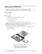
...HP Pavilion 4x00, HP Compaq nx9005 and nx9000, Compaq Evo Notebook N1050v and N1010v, and Compaq Presario 2100 and 1100 models. Removing the CD/DVD Drive HP Pavilion 4x00, HP Compaq nx9005 and nx9000, Compaq Evo Notebook N1050v and N1010v, and Compaq Presario 2100 and 1100 Models 2-20 Removal and Replacement Service Manual ...(page 2-13) • Keyboard (page 2-16) 3. Remove the CD/DVD drive. NOTE: The screws that secure the CD/DVD drive to the top case and motherboard. The back screw is a M2.5×6.0mm screw. Removing the CD/DVD Drive NOTE: This section applies only to release...
...HP Pavilion 4x00, HP Compaq nx9005 and nx9000, Compaq Evo Notebook N1050v and N1010v, and Compaq Presario 2100 and 1100 models. Removing the CD/DVD Drive HP Pavilion 4x00, HP Compaq nx9005 and nx9000, Compaq Evo Notebook N1050v and N1010v, and Compaq Presario 2100 and 1100 Models 2-20 Removal and Replacement Service Manual ...(page 2-13) • Keyboard (page 2-16) 3. Remove the CD/DVD drive. NOTE: The screws that secure the CD/DVD drive to the top case and motherboard. The back screw is a M2.5×6.0mm screw. Removing the CD/DVD Drive NOTE: This section applies only to release...

Maintenance and Service Guide
Page 51
... finger in the top case opening and push out on the CD/DVD drive to the top case and motherboard. 4. Removing the CD/DVD Drive HP Pavilion 5x00, HP Compaq nx9010 and HP nx9008, and Compaq Presario 2500 Models Service Manual Removal and Replacement 2-21 Remove these additional assemblies: • Keyboard cover (page 2-13) • Keyboard (page 2-16...
... finger in the top case opening and push out on the CD/DVD drive to the top case and motherboard. 4. Removing the CD/DVD Drive HP Pavilion 5x00, HP Compaq nx9010 and HP nx9008, and Compaq Presario 2500 Models Service Manual Removal and Replacement 2-21 Remove these additional assemblies: • Keyboard cover (page 2-13) • Keyboard (page 2-16...
Maintenance and Service Guide
Page 52
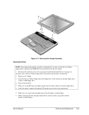
...motherboard. 6. Remove the six M2.5×6.0mm retaining screws that secure the display assembly to the top case. (Note that there is a grounding strap at the left and right antenna PCAs. Unplug the AC adapter, if present, and then remove the battery. 2. Relocate the antenna PCAs away from the notebook rear panel. 4. Remove... the keyboard cover (page 2-13). 3. Remove the two M2.5×6.0mm retaining screws from the display assembly...
...motherboard. 6. Remove the six M2.5×6.0mm retaining screws that secure the display assembly to the top case. (Note that there is a grounding strap at the left and right antenna PCAs. Unplug the AC adapter, if present, and then remove the battery. 2. Relocate the antenna PCAs away from the notebook rear panel. 4. Remove... the keyboard cover (page 2-13). 3. Remove the two M2.5×6.0mm retaining screws from the display assembly...
Maintenance and Service Guide
Page 53
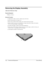
Download the notebook series service package from the floppy drive. 6. Turn on the motherboard for the new display. 1. Service Manual Removal and Replacement 2-23 Removing the Display Assembly NOTE: After replacing the display assembly or motherboard, you connect the grounding strap to the left display assembly hinge. •...make sure they are parallel with the display assembly hinges. Select the option to update the display/LCD identification stored on the motherboard. • Make sure you must use the Service Utilities floppy disk to display the boot menu, then boot from the ...
Download the notebook series service package from the floppy drive. 6. Turn on the motherboard for the new display. 1. Service Manual Removal and Replacement 2-23 Removing the Display Assembly NOTE: After replacing the display assembly or motherboard, you connect the grounding strap to the left display assembly hinge. •...make sure they are parallel with the display assembly hinges. Select the option to update the display/LCD identification stored on the motherboard. • Make sure you must use the Service Utilities floppy disk to display the boot menu, then boot from the ...

Maintenance and Service Guide
Page 54
...motherboard. 2-24 Removal and Replacement Service Manual Lift the top case off of the notebook and then disconnect the touch pad cable from the top case. 9. Removing the Top Case (Service Partners Only) NOTE: This section applies only to HP Pavilion 4x00, HP Compaq nx9005 and nx9000, Compaq Evo Notebook N1050v and N1010v, and Compaq Presario... 2100 and 1100 models. Remove these additional assemblies: • Hard disk drive (page 2-9) •...
...motherboard. 2-24 Removal and Replacement Service Manual Lift the top case off of the notebook and then disconnect the touch pad cable from the top case. 9. Removing the Top Case (Service Partners Only) NOTE: This section applies only to HP Pavilion 4x00, HP Compaq nx9005 and nx9000, Compaq Evo Notebook N1050v and N1010v, and Compaq Presario... 2100 and 1100 models. Remove these additional assemblies: • Hard disk drive (page 2-9) •...

Maintenance and Service Guide
Page 59
.... Required Equipment 1 Phillips screwdriver Removal Procedure 1. Disconnect the motherboard cable. 5. Service Manual Removal and Replacement 2-29 Remove the two M2.5×4.0mm screws (right side) that secure the hard disk drive guide to HP Pavilion ze4x00, HP Compaq nx9005 and nx9000, Compaq Evo Notebook N1050v and N1010v, and Compaq Presario 2100 and 1100 models. Remove these additional assemblies: • Hard...
.... Required Equipment 1 Phillips screwdriver Removal Procedure 1. Disconnect the motherboard cable. 5. Service Manual Removal and Replacement 2-29 Remove the two M2.5×4.0mm screws (right side) that secure the hard disk drive guide to HP Pavilion ze4x00, HP Compaq nx9005 and nx9000, Compaq Evo Notebook N1050v and N1010v, and Compaq Presario 2100 and 1100 models. Remove these additional assemblies: • Hard...
Maintenance and Service Guide
Page 60
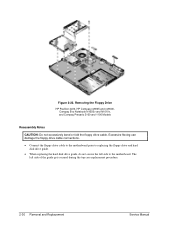
Removing the Floppy Drive HP Pavilion 4x00, HP Compaq nx9005 and nx9000, Compaq Evo Notebook N1050v and N1010v, and Compaq Presario 2100 and 1100 Models Reassembly Notes CAUTION: Do not excessively bend or fold the floppy drive cable. Excessive flexing can damage the floppy drive cable connections. • Connect the floppy drive cable to the motherboard prior to...
Removing the Floppy Drive HP Pavilion 4x00, HP Compaq nx9005 and nx9000, Compaq Evo Notebook N1050v and N1010v, and Compaq Presario 2100 and 1100 Models Reassembly Notes CAUTION: Do not excessively bend or fold the floppy drive cable. Excessive flexing can damage the floppy drive cable connections. • Connect the floppy drive cable to the motherboard prior to...
Maintenance and Service Guide
Page 64
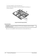
Damaging the cable can degrade notebook performance. Make sure you route the I /R PCA. Remove the I /R PCA cable between the left screw hole and the bottom case. 2-34 Removal and Replacement Service Manual Remove the two M2.5×4.0mm screws that secure the I /R PCA cable from the motherboard. 4. 3. Reassembly Note Figure 2-24. Disconnect the I /R PCA to the bottom case. 5. Removing the I/R PCA CAUTION: Use care when handling the I/R PCA cable.
Damaging the cable can degrade notebook performance. Make sure you route the I /R PCA. Remove the I /R PCA cable between the left screw hole and the bottom case. 2-34 Removal and Replacement Service Manual Remove the two M2.5×4.0mm screws that secure the I /R PCA cable from the motherboard. 4. 3. Reassembly Note Figure 2-24. Disconnect the I /R PCA to the bottom case. 5. Removing the I/R PCA CAUTION: Use care when handling the I/R PCA cable.
Maintenance and Service Guide
Page 65
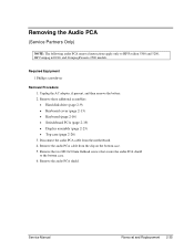
...) 3. Remove the audio PCA cable from the motherboard. 4. Remove the audio PCA shield. Removing the Audio PCA (Service Partners Only) NOTE: The following audio PCA removal instructions apply only to the bottom case. 6. Remove the two M2.0×3.0mm flathead screws that secure the audio PCA shield to HP Pavilion 5300 and 5200, HP Compaq nx9010, and Compaq Presario 2500...
...) 3. Remove the audio PCA cable from the motherboard. 4. Remove the audio PCA shield. Removing the Audio PCA (Service Partners Only) NOTE: The following audio PCA removal instructions apply only to the bottom case. 6. Remove the two M2.0×3.0mm flathead screws that secure the audio PCA shield to HP Pavilion 5300 and 5200, HP Compaq nx9010, and Compaq Presario 2500...
Maintenance and Service Guide
Page 68
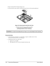
Figure 2-26. Lift up on the heat sink. 2-38 Removal and Replacement Service Manual Fully tighten the screws in this order: 1. Removing the Heat Sink (with Fan) HP Pavilion 4x00, HP Compaq nx9005 and nx9000, Compaq Evo Notebook N1050v and N1010v, and Compaq Presario 2100 and 1100 Models CAUTION: Do not spin the fan blades with fan),...damage the fan's bearings. Install all 3 screws lightly. 2. 3. Reassembly Notes • If the thermal pad is damaged, use a sharp knife or scraper to carefully remove it from the motherboard. Remove the three M2.5×4.0mm retaining screws. 4.
Figure 2-26. Lift up on the heat sink. 2-38 Removal and Replacement Service Manual Fully tighten the screws in this order: 1. Removing the Heat Sink (with Fan) HP Pavilion 4x00, HP Compaq nx9005 and nx9000, Compaq Evo Notebook N1050v and N1010v, and Compaq Presario 2100 and 1100 Models CAUTION: Do not spin the fan blades with fan),...damage the fan's bearings. Install all 3 screws lightly. 2. 3. Reassembly Notes • If the thermal pad is damaged, use a sharp knife or scraper to carefully remove it from the motherboard. Remove the three M2.5×4.0mm retaining screws. 4.

Maintenance and Service Guide
Page 70
Figure 2-27. Reassembly Notes • If the thermal pad is damaged, use a sharp knife or scraper to carefully remove it from the motherboard. 4. Install all 4 screws lightly. 2. Fully tighten the screws in the order stamped on the heat sink. 5. Disconnect the 2... "2," "3," "4" sequence stamped on the heat sink. 2-40 Removal and Replacement Service Manual Remove the 4 retaining M2.0×5.0mm screws in this order: 1. Removing the Heat Sink (with Fan) HP Pavilion 5x00, HP Compaq nx9010 and nx9008, and Compaq Presario 2500 Models CAUTION: Do not spin the fan blades with fan)....
Figure 2-27. Reassembly Notes • If the thermal pad is damaged, use a sharp knife or scraper to carefully remove it from the motherboard. 4. Install all 4 screws lightly. 2. Fully tighten the screws in the order stamped on the heat sink. 5. Disconnect the 2... "2," "3," "4" sequence stamped on the heat sink. 2-40 Removal and Replacement Service Manual Remove the 4 retaining M2.0×5.0mm screws in this order: 1. Removing the Heat Sink (with Fan) HP Pavilion 5x00, HP Compaq nx9010 and nx9008, and Compaq Presario 2500 Models CAUTION: Do not spin the fan blades with fan)....

Maintenance and Service Guide
Page 72
... turn clockwise to secure the CPU module. 2-42 Removal and Replacement Service Manual Intel CPU Module Removal HP Pavilion 4x00, HP Compaq nx9005 and nx9000, Compaq Evo Notebook N1050v and N1010v, and Compaq Presario 2100 and 1100 Models CAUTION: Each time you install... a new CPU module, you should here a light snap) to step 4. On models using an AMD CPU, proceed to release the CPU module ( see Figure 2-28). Figure 2-28. c. Depending on the motherboard...
... turn clockwise to secure the CPU module. 2-42 Removal and Replacement Service Manual Intel CPU Module Removal HP Pavilion 4x00, HP Compaq nx9005 and nx9000, Compaq Evo Notebook N1050v and N1010v, and Compaq Presario 2100 and 1100 Models CAUTION: Each time you install... a new CPU module, you should here a light snap) to step 4. On models using an AMD CPU, proceed to release the CPU module ( see Figure 2-28). Figure 2-28. c. Depending on the motherboard...


