
Maintenance and Service Guide
Page 3
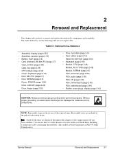
... ...1-18 Internal Design...1-24 Removal and Replacement 2-1 Disassembly Flowchart ...2-3 Removing the Battery ...2-4 Removing an SDRAM Module...2-5 Removing the Wireless LAN Mini PCI Card 2-7 Removing the Hard Disk Drive...2-9 Recovering the Factory Software...2-11 Replacing Small Parts ...2-12 Removing the Keyboard ... Fan 2-40 Removing the CPU Module ...2-44 Removing the RJ11/1394 Connector Module 2-48 Removing the Motherboard ...2-50 Replacing Components on a Bottom Case 2-59 Repairing the BIOS IC...2-61 Removing Other Components...2-63 Troubleshooting and Diagnostics 3-1 Support Service...
... ...1-18 Internal Design...1-24 Removal and Replacement 2-1 Disassembly Flowchart ...2-3 Removing the Battery ...2-4 Removing an SDRAM Module...2-5 Removing the Wireless LAN Mini PCI Card 2-7 Removing the Hard Disk Drive...2-9 Recovering the Factory Software...2-11 Replacing Small Parts ...2-12 Removing the Keyboard ... Fan 2-40 Removing the CPU Module ...2-44 Removing the RJ11/1394 Connector Module 2-48 Removing the Motherboard ...2-50 Replacing Components on a Bottom Case 2-59 Repairing the BIOS IC...2-61 Removing Other Components...2-63 Troubleshooting and Diagnostics 3-1 Support Service...

Maintenance and Service Guide
Page 4
Bottom View...1-13 Figure 1-7. Disassembly Flow...2-3 Figure 2-2. Removing the Battery ...2-4 Figure 2-3. Removing the Hard Disk Drive 2-9 Figure 2-8. Removing the Switchboard PCA 2-19 Figure 2-15. Removing the Display ... the Hard Disk Drive Guide 2-53 iv Service Manual Front View...1-8 Figure 1-2. Back View ...1-9 Figure 1-3. Bottom View...1-10 Figure 1-4. Resetting the Notebook ...1-17 Figure 1-8. Replaceable Module Diagram 1-24 Figure 2-1. Removing an SDRAM Module 2-5 Figure 2-4. Removing an SDRAM Module 2-6 Figure 2-5. Removing the Mini PCI Card 2-8 Figure...
Bottom View...1-13 Figure 1-7. Disassembly Flow...2-3 Figure 2-2. Removing the Battery ...2-4 Figure 2-3. Removing the Hard Disk Drive 2-9 Figure 2-8. Removing the Switchboard PCA 2-19 Figure 2-15. Removing the Display ... the Hard Disk Drive Guide 2-53 iv Service Manual Front View...1-8 Figure 1-2. Back View ...1-9 Figure 1-3. Bottom View...1-10 Figure 1-4. Resetting the Notebook ...1-17 Figure 1-8. Replaceable Module Diagram 1-24 Figure 2-1. Removing an SDRAM Module 2-5 Figure 2-4. Removing an SDRAM Module 2-6 Figure 2-5. Removing the Mini PCI Card 2-8 Figure...
Maintenance and Service Guide
Page 31
... discharge can damage the notebook. (The symbol at the end of each section below. You can use these are included at the left represents an M2.5×4.0mm T-head screw). Removal Cross-Reference Assembly, display (page 2-23) • Assembly, speaker (page 2-15) • Battery, main (page 2-4) ...install them. Symbols like these to verify the sizes of the removal steps. NOTE: Reassembly steps are user-replaceable. Installing a wrong-size screw can damage the notebook and its components. The items marked by • in the following table are the reverse of screws before...
... discharge can damage the notebook. (The symbol at the end of each section below. You can use these are included at the left represents an M2.5×4.0mm T-head screw). Removal Cross-Reference Assembly, display (page 2-23) • Assembly, speaker (page 2-15) • Battery, main (page 2-4) ...install them. Symbols like these to verify the sizes of the removal steps. NOTE: Reassembly steps are user-replaceable. Installing a wrong-size screw can damage the notebook and its components. The items marked by • in the following table are the reverse of screws before...
Maintenance and Service Guide
Page 34
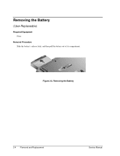
Removing the Battery (User-Replaceable) Required Equipment None Removal Procedure Slide the battery's release latch, and then pull the battery out of its compartment. Figure 2-2. Removing the Battery 2-4 Removal and Replacement Service Manual
Removing the Battery (User-Replaceable) Required Equipment None Removal Procedure Slide the battery's release latch, and then pull the battery out of its compartment. Figure 2-2. Removing the Battery 2-4 Removal and Replacement Service Manual

Maintenance and Service Guide
Page 35
...Pavilion 4x00, HP Compaq nx9005 and nx9000, Compaq Evo Notebook N1050v and N1010v, and Compaq Presario 2100 and 1100 Models Removal and Replacement 2-5 One slot contains an SDRAM module that was factory installed. Unplug the AC adapter, if present, and then remove the battery. 2. Press ... door. 3. NOTE: HP Pavilion ze5300, ze5200, ze4300, ze4200, and ze4100, HP Compaq nx9010, nx9005 and nx9000, Compaq Evo Notebook N1050v and N1010v, and Compaq Presario 2500, 2100, and 1100 notebooks use only DDR266 SDRAM modules. Required Equipment 1 Phillips screwdriver Removal Procedure 1. On the bottom...
...Pavilion 4x00, HP Compaq nx9005 and nx9000, Compaq Evo Notebook N1050v and N1010v, and Compaq Presario 2100 and 1100 Models Removal and Replacement 2-5 One slot contains an SDRAM module that was factory installed. Unplug the AC adapter, if present, and then remove the battery. 2. Press ... door. 3. NOTE: HP Pavilion ze5300, ze5200, ze4300, ze4200, and ze4100, HP Compaq nx9010, nx9005 and nx9000, Compaq Evo Notebook N1050v and N1010v, and Compaq Presario 2500, 2100, and 1100 notebooks use only DDR266 SDRAM modules. Required Equipment 1 Phillips screwdriver Removal Procedure 1. On the bottom...

Maintenance and Service Guide
Page 37
... PCI Card HP Pavilion ze4x00, HP Compaq nx9005 and nx9000, Compaq Evo Notebook N1050v and N1010v, and Compaq Presario 2100 and 1100 Models Service Manual Removal and Replacement 2-7 Press outward on the bottom of the notebook. Required Equipment 0 Phillips screwdriver Removal ...door, and then remove the door. Removing the Wireless LAN Mini PCI Card (User-Replaceable) Certain notebooks include a wireless LAN Mini PCI card under the Mini PCI door on the latches... card. 4. Damaged cables or connectors can degrade notebook performance. 3. Unplug the AC adapter, if present, and then remove the...
... PCI Card HP Pavilion ze4x00, HP Compaq nx9005 and nx9000, Compaq Evo Notebook N1050v and N1010v, and Compaq Presario 2100 and 1100 Models Service Manual Removal and Replacement 2-7 Press outward on the bottom of the notebook. Required Equipment 0 Phillips screwdriver Removal ...door, and then remove the door. Removing the Wireless LAN Mini PCI Card (User-Replaceable) Certain notebooks include a wireless LAN Mini PCI card under the Mini PCI door on the latches... card. 4. Damaged cables or connectors can degrade notebook performance. 3. Unplug the AC adapter, if present, and then remove the...

Maintenance and Service Guide
Page 39
...Hard Disk Drive Service Manual Removal and Replacement 2-9 Removing the Hard Disk Drive (User-Replaceable) Required Equipment 1 Phillips screwdriver Removal ...Procedure NOTE: If you are installing a new hard disk drive, load the factory software and operating system on the drive as described in "Recovering the Factory Software", as shown on the next page. 1. Figure 2-7. On the bottom of the notebook..., remove the hard disk drive rubber screw plugs and M2.5×6.0mm screws. (The number of the notebook. Unplug...
...Hard Disk Drive Service Manual Removal and Replacement 2-9 Removing the Hard Disk Drive (User-Replaceable) Required Equipment 1 Phillips screwdriver Removal ...Procedure NOTE: If you are installing a new hard disk drive, load the factory software and operating system on the drive as described in "Recovering the Factory Software", as shown on the next page. 1. Figure 2-7. On the bottom of the notebook..., remove the hard disk drive rubber screw plugs and M2.5×6.0mm screws. (The number of the notebook. Unplug...
Maintenance and Service Guide
Page 43
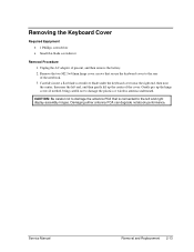
...: Be careful not to damage the antenna PCA that secure the keyboard cover to damage the plastics or wireless antenna underneath. Service Manual Removal and Replacement 2-13 Unplug the AC adapter, if present, and then remove the battery. 2. Damaging either antenna PCA can degrade notebook performance. Gently pry up the center of the...
...: Be careful not to damage the antenna PCA that secure the keyboard cover to damage the plastics or wireless antenna underneath. Service Manual Removal and Replacement 2-13 Unplug the AC adapter, if present, and then remove the battery. 2. Damaging either antenna PCA can degrade notebook performance. Gently pry up the center of the...
Maintenance and Service Guide
Page 45
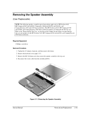
... top case and speakers on the HP Pavilion 5x00, HP Compaq nx9010 and nx9008, and Compaq Presario 2500 Series notebooks. Refer to HP Pavilion 4x00, HP Compaq nx9005 and nx9000, Compaq Evo Notebook N1050v and N1010v, and Compaq Presario 2100 and 1100 Series notebooks. Removing the Speaker Assembly Service Manual Removal and Replacement 2-15 Remove the M2.5×6.0mm screw that secures...
... top case and speakers on the HP Pavilion 5x00, HP Compaq nx9010 and nx9008, and Compaq Presario 2500 Series notebooks. Refer to HP Pavilion 4x00, HP Compaq nx9005 and nx9000, Compaq Evo Notebook N1050v and N1010v, and Compaq Presario 2100 and 1100 Series notebooks. Removing the Speaker Assembly Service Manual Removal and Replacement 2-15 Remove the M2.5×6.0mm screw that secures...

Maintenance and Service Guide
Page 46
... on the top case, forward of the keyboard into their slots in the top case, and then lower the keyboard into place. 2-16 Removal and Replacement Service Manual Remove the four M2.5×4.0mm screws that secure the keyboard to release the tabs from the top case. 5. Remove the keyboard cover...). 3. Reassembly Notes CAUTION: Do not excessively bend or fold the keyboard cable. Remove the keyboard. Unplug the AC adapter, if present, and then remove the battery. 2. Removing the Keyboard Required Equipment 1 Phillips screwdriver Removal Procedure 1.
... on the top case, forward of the keyboard into their slots in the top case, and then lower the keyboard into place. 2-16 Removal and Replacement Service Manual Remove the four M2.5×4.0mm screws that secure the keyboard to release the tabs from the top case. 5. Remove the keyboard cover...). 3. Reassembly Notes CAUTION: Do not excessively bend or fold the keyboard cable. Remove the keyboard. Unplug the AC adapter, if present, and then remove the battery. 2. Removing the Keyboard Required Equipment 1 Phillips screwdriver Removal Procedure 1.

Maintenance and Service Guide
Page 48
Figure 2-13. Removing the Switchboard PCA HP Pavilion 4x00, HP Compaq nx9005 and nx9000, Compaq Evo Notebook N1050v and N1010v, and Compaq Presario 2100 and 1100 Models 2-18 Removal and Replacement Service Manual Disconnect both the 2-wire and 4-wire cables that secures the keyboard, and then switchboard... to HP Pavilion 4x00, HP Compaq nx9005 and nx9000, Compaq Evo Notebook N1050v and N1010v, and Compaq Presario 2100 and 1100 models. Remove the keyboard cover (page 2-13). 3. Unplug the AC adapter, if present, and then remove the battery. 2. Removing the Switchboard PCA NOTE...
Figure 2-13. Removing the Switchboard PCA HP Pavilion 4x00, HP Compaq nx9005 and nx9000, Compaq Evo Notebook N1050v and N1010v, and Compaq Presario 2100 and 1100 Models 2-18 Removal and Replacement Service Manual Disconnect both the 2-wire and 4-wire cables that secures the keyboard, and then switchboard... to HP Pavilion 4x00, HP Compaq nx9005 and nx9000, Compaq Evo Notebook N1050v and N1010v, and Compaq Presario 2100 and 1100 models. Remove the keyboard cover (page 2-13). 3. Unplug the AC adapter, if present, and then remove the battery. 2. Removing the Switchboard PCA NOTE...

Maintenance and Service Guide
Page 49
... AC adapter, if present, and then remove the battery. 2. Remove the two M2.5×4.0mm screws that connects the switchboard PCA to the top case. 5. Removing the Switchboard PCA HP Pavilion 5x00, HP Compaw nx9010 and nx9008, and Compaq Presario 2500 Models Service Manual Removal and Replacement 2-19 Required Equipment 1 Phillips screwdriver Removal Procedure 1. Gently...
... AC adapter, if present, and then remove the battery. 2. Remove the two M2.5×4.0mm screws that connects the switchboard PCA to the top case. 5. Removing the Switchboard PCA HP Pavilion 5x00, HP Compaw nx9010 and nx9008, and Compaq Presario 2500 Models Service Manual Removal and Replacement 2-19 Required Equipment 1 Phillips screwdriver Removal Procedure 1. Gently...
Maintenance and Service Guide
Page 50
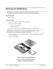
Unplug the AC adapter, if present, and then remove the battery. 2. Remove these screws are 2 different sizes. NOTE: The screws that secure the CD/DVD drive to the top case and motherboard. The front screw is a ... the correct locations when reinstalling the CD/DVD drive. 4. Removing the CD/DVD Drive HP Pavilion 4x00, HP Compaq nx9005 and nx9000, Compaq Evo Notebook N1050v and N1010v, and Compaq Presario 2100 and 1100 Models 2-20 Removal and Replacement Service Manual Make sure these additional assemblies: • Keyboard cover (page 2-13) • Keyboard (page 2-16) 3. Figure...
Unplug the AC adapter, if present, and then remove the battery. 2. Remove these screws are 2 different sizes. NOTE: The screws that secure the CD/DVD drive to the top case and motherboard. The front screw is a ... the correct locations when reinstalling the CD/DVD drive. 4. Removing the CD/DVD Drive HP Pavilion 4x00, HP Compaq nx9005 and nx9000, Compaq Evo Notebook N1050v and N1010v, and Compaq Presario 2100 and 1100 Models 2-20 Removal and Replacement Service Manual Make sure these additional assemblies: • Keyboard cover (page 2-13) • Keyboard (page 2-16) 3. Figure...

Maintenance and Service Guide
Page 51
... then remove the battery. 2. Remove the two M2.5×6.0mm screws that secure the CD/DVD drive to release it from the motherboard. 5. Required Equipment 1 Phillips screwdriver Removal Procedure 1. Removing the CD/DVD Drive HP Pavilion 5x00, HP Compaq nx9010 and HP nx9008, and Compaq Presario 2500 Models Service Manual Removal and Replacement 2-21 Place your...
... then remove the battery. 2. Remove the two M2.5×6.0mm screws that secure the CD/DVD drive to release it from the motherboard. 5. Required Equipment 1 Phillips screwdriver Removal Procedure 1. Removing the CD/DVD Drive HP Pavilion 5x00, HP Compaq nx9010 and HP nx9008, and Compaq Presario 2500 Models Service Manual Removal and Replacement 2-21 Place your...
Maintenance and Service Guide
Page 52
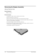
... panel. 4. Remove the M2.5×4.0mm screws from the display assembly hinges. 5. Lift the display assembly off of the notebook. 2-22 Removal and Replacement Service Manual Relocate the antenna PCAs away from the left hinge.) 7. Removing the Display Assembly (Service Partners Only) Required Equipment 1 Phillips screwdriver Removal Procedure 1. Unplug ...
... panel. 4. Remove the M2.5×4.0mm screws from the display assembly hinges. 5. Lift the display assembly off of the notebook. 2-22 Removal and Replacement Service Manual Relocate the antenna PCAs away from the left hinge.) 7. Removing the Display Assembly (Service Partners Only) Required Equipment 1 Phillips screwdriver Removal Procedure 1. Unplug ...

Maintenance and Service Guide
Page 54
... Remove the following M2.5×4.0mm screws: • One from the battery bay • One from the motherboard. 2-24 Removal and Replacement Service Manual Lift the top case off of the notebook and then disconnect the touch pad cable from the hard disk drive bay... 5. Removing the Top Case (Service Partners Only) NOTE: This section applies only to HP Pavilion 4x00, HP Compaq nx9005 and nx9000, Compaq Evo Notebook N1050v and N1010v, and Compaq Presario...
... Remove the following M2.5×4.0mm screws: • One from the battery bay • One from the motherboard. 2-24 Removal and Replacement Service Manual Lift the top case off of the notebook and then disconnect the touch pad cable from the hard disk drive bay... 5. Removing the Top Case (Service Partners Only) NOTE: This section applies only to HP Pavilion 4x00, HP Compaq nx9005 and nx9000, Compaq Evo Notebook N1050v and N1010v, and Compaq Presario...

Maintenance and Service Guide
Page 56
Unplug the AC adapter, if present, and then remove the battery. 2. Turn the notebook bottom side up with the front facing forward. 4. Be sure to the notebook. 2-26 Removal and Replacement Service Manual Failure to follow this caution can result in damage to note of the correct location of each side of the docking connector...; Switchboard PCA (page 2-19) • CD/DVD drive (page 2-20) • Display assembly (page 2-23) 3. NOTE: This section applies only to HP Pavilion 5x00, HP Compaq nx9010 and HP nx9008, and Compaq Presario 2500 models.
Unplug the AC adapter, if present, and then remove the battery. 2. Turn the notebook bottom side up with the front facing forward. 4. Be sure to the notebook. 2-26 Removal and Replacement Service Manual Failure to follow this caution can result in damage to note of the correct location of each side of the docking connector...; Switchboard PCA (page 2-19) • CD/DVD drive (page 2-20) • Display assembly (page 2-23) 3. NOTE: This section applies only to HP Pavilion 5x00, HP Compaq nx9010 and HP nx9008, and Compaq Presario 2500 models.

Maintenance and Service Guide
Page 59
...Replacement 2-29 Required Equipment 1 Phillips screwdriver Removal Procedure 1. Remove the two M2.5×4.0mm screws (right side) that secure the hard disk drive guide to the motherboard. (Note that secure the floppy drive to HP Pavilion ze4x00, HP Compaq nx9005 and nx9000, Compaq Evo Notebook N1050v and N1010v, and Compaq Presario... 2100 and 1100 models. These screws were removed during the top case removal procedure.) 4. Unplug the AC adapter, if present, and remove the battery. 2.
...Replacement 2-29 Required Equipment 1 Phillips screwdriver Removal Procedure 1. Remove the two M2.5×4.0mm screws (right side) that secure the hard disk drive guide to the motherboard. (Note that secure the floppy drive to HP Pavilion ze4x00, HP Compaq nx9005 and nx9000, Compaq Evo Notebook N1050v and N1010v, and Compaq Presario... 2100 and 1100 models. These screws were removed during the top case removal procedure.) 4. Unplug the AC adapter, if present, and remove the battery. 2.

Maintenance and Service Guide
Page 61
...;3.0mm screw that secures the floppy drive bezel to HP Pavilion 5x00, HP Compaq nx9010 and nx9008, and Compaq Presario 2500 models. Remove the floppy drive. 6. Service Manual Removal and Replacement 2-31 Unplug the AC adapter, if present, and then remove the battery. 2. NOTE: This section applies only to the floppy drive. 7. Required Equipment • 1 Phillips...
...;3.0mm screw that secures the floppy drive bezel to HP Pavilion 5x00, HP Compaq nx9010 and nx9008, and Compaq Presario 2500 models. Remove the floppy drive. 6. Service Manual Removal and Replacement 2-31 Unplug the AC adapter, if present, and then remove the battery. 2. NOTE: This section applies only to the floppy drive. 7. Required Equipment • 1 Phillips...

Maintenance and Service Guide
Page 63
Remove these additional assemblies: • Hard disk drive (page 2-9) • Keyboard cover (page 2-13) • Keyboard (page 2-16) • Switchboard PCA (page 2-19) • Display assembly (page 2-23) • Top case (page 2-26) Service Manual Removal and Replacement 2-33 Unplug the AC adapter, if present, and then remove the battery. 2. Removing the Infrared (I/R) PCA (Service Partners Only) Required Equipment 1 Phillips screwdriver Removal Procedure 1.
Remove these additional assemblies: • Hard disk drive (page 2-9) • Keyboard cover (page 2-13) • Keyboard (page 2-16) • Switchboard PCA (page 2-19) • Display assembly (page 2-23) • Top case (page 2-26) Service Manual Removal and Replacement 2-33 Unplug the AC adapter, if present, and then remove the battery. 2. Removing the Infrared (I/R) PCA (Service Partners Only) Required Equipment 1 Phillips screwdriver Removal Procedure 1.


