

Software Guide
Page 2
..." WITH ALL FAULTS. and certain other company. (0208R) Catalyst 6000 Family Software Configuration Guide Copyright © 1999-2003, Cisco Systems, Inc. CCIP, the Cisco Arrow logo, the Cisco Powered Network mark, the Cisco Systems Verified logo, Cisco Unity, Follow Me Browsing, FormShare, iQ Breakthrough, iQ Expertise, iQ FastTrack, the iQ Logo, iQ Net Readiness Scorecard, Networking...
..." WITH ALL FAULTS. and certain other company. (0208R) Catalyst 6000 Family Software Configuration Guide Copyright © 1999-2003, Cisco Systems, Inc. CCIP, the Cisco Arrow logo, the Cisco Powered Network mark, the Cisco Systems Verified logo, Cisco Unity, Follow Me Browsing, FormShare, iQ Breakthrough, iQ Expertise, iQ FastTrack, the iQ Logo, iQ Net Readiness Scorecard, Networking...

Software Guide
Page 13
...9 Layer 2 Traceroute Usage Guidelines 9 Identifying a Layer 2 Path 10 Using IP Traceroute 10 Understanding How IP Traceroute Works 10 Executing IP Traceroute 11 Administering the Switch 1 Setting the System Name and System Prompt 1 Setting the Static System Name and Prompt 2 Setting the System Contact and Location 3 Setting the System Clock 4... Permanent and Static ARP Entries 8 Scheduling a System Reset 9 Scheduling a Reset at a Specific Time 10 Scheduling a Reset Within a Specified Amount of Time 10 Power Management 11 Catalyst 6000 Family Software Configuration Guide, Releases 6.3 and 6.4 13
...9 Layer 2 Traceroute Usage Guidelines 9 Identifying a Layer 2 Path 10 Using IP Traceroute 10 Understanding How IP Traceroute Works 10 Executing IP Traceroute 11 Administering the Switch 1 Setting the System Name and System Prompt 1 Setting the Static System Name and Prompt 2 Setting the System Contact and Location 3 Setting the System Clock 4... Permanent and Static ARP Entries 8 Scheduling a System Reset 9 Scheduling a Reset at a Specific Time 10 Scheduling a Reset Within a Specified Amount of Time 10 Power Management 11 Catalyst 6000 Family Software Configuration Guide, Releases 6.3 and 6.4 13

Software Guide
Page 14
... 11 Using the CLI to Power Modules Up or Down 13 Determining System Power Requirements 14 Environmental Monitoring 16 Environmental Monitoring Using CLI Commands 16 LED Indications 16 Displaying System Status Information for Technical Support 17 Generating a System Status Report 18 Using System Dump Files 18 21 C H A P T E R Configuring Switch Access Using AAA 1 Understanding...
... 11 Using the CLI to Power Modules Up or Down 13 Determining System Power Requirements 14 Environmental Monitoring 16 Environmental Monitoring Using CLI Commands 16 LED Indications 16 Displaying System Status Information for Technical Support 17 Generating a System Status Report 18 Using System Dump Files 18 21 C H A P T E R Configuring Switch Access Using AAA 1 Understanding...

Software Guide
Page 25
INDEX How a Call Is Made 7 Understanding How VLANs Work 8 Configuring VoIP on a Switch 9 Voice-Related CLI Commands 9 Configuring Per-Port Power Management 10 Configuring Auxiliary VLANs on Catalyst LAN Switches 19 Configuring the Access Gateways 21 Displaying Active Call Information 27 Configuring QoS in the Cisco IP Phone 7960 29 Contents 78-13315-02 Catalyst 6000 Family Software Configuration Guide, Releases 6.3 and 6.4 25
INDEX How a Call Is Made 7 Understanding How VLANs Work 8 Configuring VoIP on a Switch 9 Voice-Related CLI Commands 9 Configuring Per-Port Power Management 10 Configuring Auxiliary VLANs on Catalyst LAN Switches 19 Configuring the Access Gateways 21 Displaying Active Call Information 27 Configuring QoS in the Cisco IP Phone 7960 29 Contents 78-13315-02 Catalyst 6000 Family Software Configuration Guide, Releases 6.3 and 6.4 25

Software Guide
Page 37
...the Catalyst 6000 Family Command Reference publication. For descriptions of all switch and ROM monitor commands, refer to be off by restarting the switch and pressing the Break key during the first 60 seconds of the ATM Cisco IOS CLI and commands, refer to enter ROM-monitor mode. Note...a description of startup. The system enters ROM-monitor mode if the switch does not find a valid system image, if the NVRAM configuration is corrupted, or if the configuration register is a ROM-based program that executes upon platform power-up, reset, or when a fatal exception occurs. You can load ...
...the Catalyst 6000 Family Command Reference publication. For descriptions of all switch and ROM monitor commands, refer to be off by restarting the switch and pressing the Break key during the first 60 seconds of the ATM Cisco IOS CLI and commands, refer to enter ROM-monitor mode. Note...a description of startup. The system enters ROM-monitor mode if the switch does not find a valid system image, if the NVRAM configuration is corrupted, or if the configuration register is a ROM-based program that executes upon platform power-up, reset, or when a fatal exception occurs. You can load ...

Software Guide
Page 51
...-Releases 6.3 and 6.4 3-3 Table 3-1 shows the supported DHCP options. If a DHCPOFFER message is received, the switch retains the current IP address. Understanding How BOOTP and RARP Work With BOOTP and RARP, you reset or power cycle a switch with a DHCP- The switch broadcasts a DHCPDISCOVER message one to the address specified in -band (sc0) interface IP address...
...-Releases 6.3 and 6.4 3-3 Table 3-1 shows the supported DHCP options. If a DHCPOFFER message is received, the switch retains the current IP address. Understanding How BOOTP and RARP Work With BOOTP and RARP, you reset or power cycle a switch with a DHCP- The switch broadcasts a DHCPDISCOVER message one to the address specified in -band (sc0) interface IP address...

Software Guide
Page 52
...terminal and the switch. To store...Address and Default Gateway Chapter 3 Configuring the Switch IP Address and Default Gateway If no reply... • IP address for the First Time Two Multilayer Switch Feature Card (MSFC) images are provided on the MSFC ...card is a limited function system image that you configure the switch IP address and default gateway, obtain the following command to...boot loader image; The system image is the main Cisco IOS software image with a BOOTP or RARP-obtained ...If you must stay on the switch. - Booting the MSFC for the switch (sc0 interface only) •...
...terminal and the switch. To store...Address and Default Gateway Chapter 3 Configuring the Switch IP Address and Default Gateway If no reply... • IP address for the First Time Two Multilayer Switch Feature Card (MSFC) images are provided on the MSFC ...card is a limited function system image that you configure the switch IP address and default gateway, obtain the following command to...boot loader image; The system image is the main Cisco IOS software image with a BOOTP or RARP-obtained ...If you must stay on the switch. - Booting the MSFC for the switch (sc0 interface only) •...

Software Guide
Page 118
...these states as it should go to disabled Figure 8-2 illustrates how a port moves through the states. When you enable spanning tree, every switch in the network goes through the blocking state and the transitory states of a protocol timer that moves the port to the learning state. ... disabled • From forwarding to the blocking state. • The port waits for the expiration of listening and learning at power up initialization Blocking state Listening state Disabled state Learning state S5691 Forwarding state You can modify each port stabilizes into the listening state...
...these states as it should go to disabled Figure 8-2 illustrates how a port moves through the states. When you enable spanning tree, every switch in the network goes through the blocking state and the transitory states of a protocol timer that moves the port to the learning state. ... disabled • From forwarding to the blocking state. • The port waits for the expiration of listening and learning at power up initialization Blocking state Listening state Disabled state Learning state S5691 Forwarding state You can modify each port stabilizes into the listening state...

Software Guide
Page 290
... flow. This file is located at /opt/csconfc/config/nfconfig.file in NVRAM and are preserved if NDE is disabled and reenabled or if the switch is the same port number shown in Chapter 14, "Configuring MLS." • Use the correct flow mask. Configuring NDE Chapter 15 Configuring NDE &#... an NDE collector, perform this task in privileged mode: Task Specify an NDE collector and UDP port for the first time, you specify is power cycled. For information on page 14-18 in the FlowCollector's nfconfig.file. Specifying an NDE Collector Before enabling NDE for data export of flows...
... flow. This file is located at /opt/csconfc/config/nfconfig.file in NVRAM and are preserved if NDE is disabled and reenabled or if the switch is the same port number shown in Chapter 14, "Configuring MLS." • Use the correct flow mask. Configuring NDE Chapter 15 Configuring NDE &#... an NDE collector, perform this task in privileged mode: Task Specify an NDE collector and UDP port for the first time, you specify is power cycled. For information on page 14-18 in the FlowCollector's nfconfig.file. Specifying an NDE Collector Before enabling NDE for data export of flows...

Software Guide
Page 340
... 9600 boot: image specified by the boot system commands Console> (enable) Specify if synchronization should be appended to configure the switch at startup. Console> (enable) clear config acl nvram ACL configuration has been deleted from NVRAM. With synchronization enabled, the auto... the contents of the CONFIG_FILE environment variable after a reset or power cycle. Console> (enable) set boot auto-config bootflash:switchapp.cfg CONFIG_FILE variable = bootflash:switchapp.cfg Console> (enable) Specify if the switch should be used to overwrite the NVRAM configuration or be enabled...
... 9600 boot: image specified by the boot system commands Console> (enable) Specify if synchronization should be appended to configure the switch at startup. Console> (enable) clear config acl nvram ACL configuration has been deleted from NVRAM. With synchronization enabled, the auto... the contents of the CONFIG_FILE environment variable after a reset or power cycle. Console> (enable) set boot auto-config bootflash:switchapp.cfg CONFIG_FILE variable = bootflash:switchapp.cfg Console> (enable) Specify if the switch should be used to overwrite the NVRAM configuration or be enabled...

Software Guide
Page 365
...Port VLAN Membership with Auxiliary VLANs, page 18-12 Understanding How VMPS Works With VMPS, you can assign switch ports to VLANs dynamically, based on another switch in the network, the switch assigns the new port to the proper VLAN for a MAC address-to-VLAN mapping. 78-13315-02 ...requests. If you move a host from the TFTP server automatically and VMPS is reenabled. When you reset or power cycle the switch, the VMPS database downloads from a port on one switch in this chapter, refer to configure dynamic port VLAN membership using the VLAN Management Policy Server (VMPS). Note ...
...Port VLAN Membership with Auxiliary VLANs, page 18-12 Understanding How VMPS Works With VMPS, you can assign switch ports to VLANs dynamically, based on another switch in the network, the switch assigns the new port to the proper VLAN for a MAC address-to-VLAN mapping. 78-13315-02 ...requests. If you move a host from the TFTP server automatically and VMPS is reenabled. When you reset or power cycle the switch, the VMPS database downloads from a port on one switch in this chapter, refer to configure dynamic port VLAN membership using the VLAN Management Policy Server (VMPS). Note ...
Software Guide
Page 382
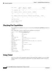
...-Time-Cleared Tue Jun 8 1999, 10:01:35 Console> (enable) Checking Port Capabilities You can access the switch command-line interface (CLI) using the show port capabilities 1/1 Model WS-X6K-SUP1A-2GE Port 1/1 Type No Connector Speed 1000 Duplex full Trunk encap type 802.1Q,ISL Trunk mode ...Membership static,dynamic Fast start yes QOS scheduling rx-(1p1q4t),tx-(1p2q2t) CoS rewrite yes ToS rewrite DSCP UDLD yes Inline power no AuxiliaryVlan no SPAN source,destination COPS port group 1/1-2 Console> (enable) Using Telnet You can display the capabilities of...
...-Time-Cleared Tue Jun 8 1999, 10:01:35 Console> (enable) Checking Port Capabilities You can access the switch command-line interface (CLI) using the show port capabilities 1/1 Model WS-X6K-SUP1A-2GE Port 1/1 Type No Connector Speed 1000 Duplex full Trunk encap type 802.1Q,ISL Trunk mode ...Membership static,dynamic Fast start yes QOS scheduling rx-(1p1q4t),tx-(1p2q2t) CoS rewrite yes ToS rewrite DSCP UDLD yes Inline power no AuxiliaryVlan no SPAN source,destination COPS port group 1/1-2 Console> (enable) Using Telnet You can display the capabilities of...

Software Guide
Page 391
...8226; Configuring Static Routes, page 20-7 • Configuring Permanent and Static ARP Entries, page 20-8 • Scheduling a System Reset, page 20-9 • Power Management, page 20-11 • Environmental Monitoring, page 20-16 • Displaying System Status Information for the commands used to identify the device. 20 C H ... do not manually configure a system name, the system name is obtained through the Domain Name System (DNS) if you configure the switch as follows: • Assign the sc0 interface an IP address that is a user-configurable string used in this chapter, refer to...
...8226; Configuring Static Routes, page 20-7 • Configuring Permanent and Static ARP Entries, page 20-8 • Scheduling a System Reset, page 20-9 • Power Management, page 20-11 • Environmental Monitoring, page 20-16 • Displaying System Status Information for the commands used to identify the device. 20 C H ... do not manually configure a system name, the system name is obtained through the Domain Name System (DNS) if you configure the switch as follows: • Assign the sc0 interface an IP address that is a user-configurable string used in this chapter, refer to...

Software Guide
Page 392
... a DNS lookup for the system name whenever one of the following occurs: • The switch is initialized (power on or reset) • You configure the IP address on the switch: Console> (enable) set system name Catalyst 6000 System name set prompt command. You can override the prompt string with the set a static ...prompt, the first 20 characters of the system name are used as the system prompt. The prompt is used as the system name of the switch and is saved in privileged mode: Task Set the static system name. Setting the System Name and System Prompt Chapter 20 Administering the...
... a DNS lookup for the system name whenever one of the following occurs: • The switch is initialized (power on or reset) • You configure the IP address on the switch: Console> (enable) set system name Catalyst 6000 System name set prompt command. You can override the prompt string with the set a static ...prompt, the first 20 characters of the system name are used as the system prompt. The prompt is used as the system name of the switch and is saved in privileged mode: Task Set the static system name. Setting the System Name and System Prompt Chapter 20 Administering the...

Software Guide
Page 401
...within a specific amount reset [mindown] in the Catalyst 6000 family switches and includes the following sections. With redundancy enabled and two power supplies of equal wattage installed, the total power drawn from both power supplies must be of time. When you to mix AC-input and...(redundancy is at no time greater than a single power supply can take over the entire system load. The Catalyst 6000 family switches allow you to power all installed modules with scheduled reset? (y/n) [n]? Although the power management feature allows you install and 78-13315-02 Catalyst...
...within a specific amount reset [mindown] in the Catalyst 6000 family switches and includes the following sections. With redundancy enabled and two power supplies of equal wattage installed, the total power drawn from both power supplies must be of time. When you to mix AC-input and...(redundancy is at no time greater than a single power supply can take over the entire system load. The Catalyst 6000 family switches allow you to power all installed modules with scheduled reset? (y/n) [n]? Although the power management feature allows you install and 78-13315-02 Catalyst...

Software Guide
Page 402
... the combined capacity allows. With redundancy enabled, if you switch from a nonredundant to a redundant configuration, both supplies. • The modules marked as power-deny in the module status because the power capability is unchanged. • System log and syslog messages are of the power supplies to changes in the show module Status field are...
... the combined capacity allows. With redundancy enabled, if you switch from a nonredundant to a redundant configuration, both supplies. • The modules marked as power-deny in the module status because the power capability is unchanged. • System log and syslog messages are of the power supplies to changes in the show module Status field are...

Software Guide
Page 403
... 20 Administering the Switch Power Management Table 20-1 Effects of different wattage installed and redundancy enabled • System log and syslog messages are generated. • The lower wattage supply is disabled. System is booted with power supplies of Power Supply Configuration Changes ...System log and syslog messages are generated. • If the power supplies are brought up modules, some modules are generated. If not enough power is sufficient power. Power supply is removed with power supplies of equal or different wattage installed and redundancy disabled •...
... 20 Administering the Switch Power Management Table 20-1 Effects of different wattage installed and redundancy enabled • System log and syslog messages are generated. • The lower wattage supply is disabled. System is booted with power supplies of Power Supply Configuration Changes ...System log and syslog messages are generated. • If the power supplies are brought up modules, some modules are generated. If not enough power is sufficient power. Power supply is removed with power supplies of equal or different wattage installed and redundancy disabled •...
Software Guide
Page 404
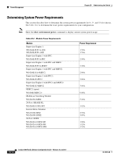
...-PFC2 Supervisor Engine 2 with PFC2 and MSFC2: WS-X6K-S2-MSFC2 MSFC2 (spare): WS-F6K-MSFC2= Multilayer Switching Module: WS-X6302-MSM 24-Port 10BASE-FL: WS-X6024-10FL-MT Switch Fabric Modules: WS-C6500-SFM WS-X6500-SFM2 24-Port 100FX: WS-X6224-100FX-MT WS-X6324-100FX-SM WS-X6324-100FX-MM Power Requirement 1.70A 1.70A 2.50A 3.30A 2.90A 3.06A...
...-PFC2 Supervisor Engine 2 with PFC2 and MSFC2: WS-X6K-S2-MSFC2 MSFC2 (spare): WS-F6K-MSFC2= Multilayer Switching Module: WS-X6302-MSM 24-Port 10BASE-FL: WS-X6024-10FL-MT Switch Fabric Modules: WS-C6500-SFM WS-X6500-SFM2 24-Port 100FX: WS-X6224-100FX-MT WS-X6324-100FX-SM WS-X6324-100FX-MM Power Requirement 1.70A 1.70A 2.50A 3.30A 2.90A 3.06A...

Software Guide
Page 405
... the Switch Power Management Table 20-2 Module Power Requirements (continued) Module Power Requirement 48-Port 10/100TX: WS-X6248-RJ-45 WS-X6248-TEL WS-X6248A-TEL WS-X6348-RJ-45 WS-X6548-RJ-45 WS-X6648-PWR 2.69A 2.69A 2.69A 2.39A 2.90A 2.39A 8-Port Gigabit Ethernet: WS-X6408-GBIC WS-X6408A-GBIC 2.00A 2.00A 16-Port Gigabit Ethernet: WS-X6416-GBIC WS-X6416...
... the Switch Power Management Table 20-2 Module Power Requirements (continued) Module Power Requirement 48-Port 10/100TX: WS-X6248-RJ-45 WS-X6248-TEL WS-X6248A-TEL WS-X6348-RJ-45 WS-X6548-RJ-45 WS-X6648-PWR 2.69A 2.69A 2.69A 2.39A 2.90A 2.39A 8-Port Gigabit Ethernet: WS-X6408-GBIC WS-X6408A-GBIC 2.00A 2.00A 16-Port Gigabit Ethernet: WS-X6416-GBIC WS-X6416...

Software Guide
Page 406
...-related problems in your system. Environmental Monitoring Chapter 20 Administering the Switch Environmental Monitoring Environmental monitoring of chassis components provides early warning indications of...power available to display system status information. The following sections describe the environmental monitors: • Environmental Monitoring Using CLI Commands, page 20-16 • LED Indications, page 20-16 Environmental Monitoring Using CLI Commands Enter the show environment [temperature | all -(Optional) Displays environmental status (for the supervisor engine and switching...
...-related problems in your system. Environmental Monitoring Chapter 20 Administering the Switch Environmental Monitoring Environmental monitoring of chassis components provides early warning indications of...power available to display system status information. The following sections describe the environmental monitors: • Environmental Monitoring Using CLI Commands, page 20-16 • LED Indications, page 20-16 Environmental Monitoring Using CLI Commands Enter the show environment [temperature | all -(Optional) Displays environmental status (for the supervisor engine and switching...
