
Hardware Installation Guide
Page 2
... OF ANY PRODUCTS. THE SOFTWARE LICENSE AND LIMITED WARRANTY FOR THE ACCOMPANYING PRODUCT ARE SET FORTH IN THE INFORMATION PACKET THAT SHIPPED WITH THE PRODUCT AND ARE INCORPORATED HEREIN BY THIS REFERENCE. These limits are designed to ucs-docfeedback@cisco.com THE SPECIFICATIONS AND INFORMATION REGARDING THE PRODUCTS IN THIS MANUAL ARE SUBJECT TO CHANGE WITHOUT NOTICE. However, there...
... OF ANY PRODUCTS. THE SOFTWARE LICENSE AND LIMITED WARRANTY FOR THE ACCOMPANYING PRODUCT ARE SET FORTH IN THE INFORMATION PACKET THAT SHIPPED WITH THE PRODUCT AND ARE INCORPORATED HEREIN BY THIS REFERENCE. These limits are designed to ucs-docfeedback@cisco.com THE SPECIFICATIONS AND INFORMATION REGARDING THE PRODUCTS IN THIS MANUAL ARE SUBJECT TO CHANGE WITHOUT NOTICE. However, there...

Hardware Installation Guide
Page 4
...2-24 Removing a Power Supply 2-24 Installing a Power Supply 2-25 Fan Modules 2-26 Replacing a Fan Module 2-26 Removing the Cisco UCS 6120XP 2-28 Removing the Cisco UCS 6140XP 2-28 Repacking the Cisco UCS Fabric Interconnect for Return Shipment 2-29 3 C H A P T E R Connecting the Cisco UCS 6100 Series Fabric Interconnect 3-1 Preparing for Network Connections 3-1 Connecting to the Console Port 3-1 Connecting to the Ethernet Connector Port 3-3 Connecting to an Ethernet Port 3-3 Installing or Removing SFP+ Transceivers 3-4 Cisco UCS 6100 Series Fabric Interconnect Hardware Installation Guide iv...
...2-24 Removing a Power Supply 2-24 Installing a Power Supply 2-25 Fan Modules 2-26 Replacing a Fan Module 2-26 Removing the Cisco UCS 6120XP 2-28 Removing the Cisco UCS 6140XP 2-28 Repacking the Cisco UCS Fabric Interconnect for Return Shipment 2-29 3 C H A P T E R Connecting the Cisco UCS 6100 Series Fabric Interconnect 3-1 Preparing for Network Connections 3-1 Connecting to the Console Port 3-1 Connecting to the Ethernet Connector Port 3-3 Connecting to an Ethernet Port 3-3 Installing or Removing SFP+ Transceivers 3-4 Cisco UCS 6100 Series Fabric Interconnect Hardware Installation Guide iv...

Hardware Installation Guide
Page 5
... Specification for SFP Transceivers A-4 B A P P E N D I X Accessory Kit for the Cisco UCS Fabric Interconnect B-1 Console Cable B-2 Console Port B-2 Supported Power Cords and Plugs B-3 AC Power Cord Illustrations B-4 Jumper Power Cord B-8 C A P P E N D I X Site Preparation Checklist C-1 Contact and Site Information C-3 Chassis and Module Information C-4 D A P P E N D I X Overview D-1 SNMP Traps D-1 System Hardware Best Practices D-2 Installation Best Practices D-2 Initialization Best Practices D-2 OL-20036-02 Cisco UCS 6100 Series Fabric Interconnect Hardware Installation Guide...
... Specification for SFP Transceivers A-4 B A P P E N D I X Accessory Kit for the Cisco UCS Fabric Interconnect B-1 Console Cable B-2 Console Port B-2 Supported Power Cords and Plugs B-3 AC Power Cord Illustrations B-4 Jumper Power Cord B-8 C A P P E N D I X Site Preparation Checklist C-1 Contact and Site Information C-3 Chassis and Module Information C-4 D A P P E N D I X Overview D-1 SNMP Traps D-1 System Hardware Best Practices D-2 Installation Best Practices D-2 Initialization Best Practices D-2 OL-20036-02 Cisco UCS 6100 Series Fabric Interconnect Hardware Installation Guide...

Hardware Installation Guide
Page 7
... Hardware Installation Guide vii Describes how to install the Cisco UCS 6100 Series Fabric Interconnect, and how to connect the Cisco UCS 6100 Series Fabric Interconnect, including the modules. Lists cable and port specifications for the Cisco UCS 6100 Series Fabric Interconnect and components including modules, power supplies, and transceivers. Describes how to install modules, power supplies, and fan assemblies. It also provides information on how to obtain related documentation. Send document comments to ucs-docfeedback@cisco.com...
... Hardware Installation Guide vii Describes how to install the Cisco UCS 6100 Series Fabric Interconnect, and how to connect the Cisco UCS 6100 Series Fabric Interconnect, including the modules. Lists cable and port specifications for the Cisco UCS 6100 Series Fabric Interconnect and components including modules, power supplies, and transceivers. Describes how to install modules, power supplies, and fan assemblies. It also provides information on how to obtain related documentation. Send document comments to ucs-docfeedback@cisco.com...

Hardware Installation Guide
Page 14
... comments to ucs-docfeedback@cisco.com Related Documentation The documentation set for the Cisco UCS 6100 Series Fabric Interconnect includes the following documents: • Cisco UCS Documentation Roadmap • Cisco UCS Manager CLI Configuration Guide • Cisco UCS Manager GUI Configuration Guide • Cisco UCS Manager CLI Command Reference • Cisco UCS Manager XML API Programmer's Guide • Cisco UCS Manager Troubleshooting Guide • Cisco UCS Site Preparation Guide • Cisco UCS 5108 Server Chassis Hardware Installation Guide • Regulatory Compliance and...
... comments to ucs-docfeedback@cisco.com Related Documentation The documentation set for the Cisco UCS 6100 Series Fabric Interconnect includes the following documents: • Cisco UCS Documentation Roadmap • Cisco UCS Manager CLI Configuration Guide • Cisco UCS Manager GUI Configuration Guide • Cisco UCS Manager CLI Command Reference • Cisco UCS Manager XML API Programmer's Guide • Cisco UCS Manager Troubleshooting Guide • Cisco UCS Site Preparation Guide • Cisco UCS 5108 Server Chassis Hardware Installation Guide • Regulatory Compliance and...
Hardware Installation Guide
Page 15
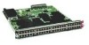
... Channel networks, and provides consolidated I/O connectivity to both production Ethernet LANs and Fibre Channel SANs in the rack. Each fan module houses six fans. OL-20036-02 Cisco UCS 6100 Series Fabric Interconnect Hardware Installation Guide 1-1 The Cisco UCS 6100 series has the following sections: • Interconnect Features, page 1-1 • Cisco UCS 6120XP Chassis, page 1-2 • Cisco UCS 6140XP Chassis, page 1-4 • Expansion Modules, page 1-6 • Ports, page 1-10 • Power Supply...
... Channel networks, and provides consolidated I/O connectivity to both production Ethernet LANs and Fibre Channel SANs in the rack. Each fan module houses six fans. OL-20036-02 Cisco UCS 6100 Series Fabric Interconnect Hardware Installation Guide 1-1 The Cisco UCS 6100 series has the following sections: • Interconnect Features, page 1-1 • Cisco UCS 6120XP Chassis, page 1-2 • Cisco UCS 6140XP Chassis, page 1-4 • Expansion Modules, page 1-6 • Ports, page 1-10 • Power Supply...

Hardware Installation Guide
Page 16
... port exposes four Ethernet ports that are in a standard 19-inch rack (the Cisco R Series Rack is 1 RU, 1.72 inches tall, 17.3 inches wide and 30.0 inches deep. Cisco UCS 6100 Series Fabric Interconnect Hardware Installation Guide 1-2 OL-20036-02 Figure 1-1 Ethernet Connector Port 1 2 186385 1 UCS cluster cross connect ports 2 Network management ports Table 1-1 lists the LED descriptions for all Ethernet LEDs. It mounts in a 2x2 stacked RJ-45 jack. The chassis has two power supplies and two fan modules...
... port exposes four Ethernet ports that are in a standard 19-inch rack (the Cisco R Series Rack is 1 RU, 1.72 inches tall, 17.3 inches wide and 30.0 inches deep. Cisco UCS 6100 Series Fabric Interconnect Hardware Installation Guide 1-2 OL-20036-02 Figure 1-1 Ethernet Connector Port 1 2 186385 1 UCS cluster cross connect ports 2 Network management ports Table 1-1 lists the LED descriptions for all Ethernet LEDs. It mounts in a 2x2 stacked RJ-45 jack. The chassis has two power supplies and two fan modules...

Hardware Installation Guide
Page 28
... 6100 Series Fabric Interconnect Hardware Installation Guide OL-20036-02 Figure 1-22 shows the 750 W power supply, which has two LEDs: one for power status and one power supply. Figure 1-20 Port Numbering of the Cisco UCS 6140XP Configured with one for redundancy, but the fabric interconnect is fully functional with the N10-E0600 Expansion Module A B C D E 186387 A Group 1/ports 1 through 16: 10-Gigabit or 1 GigabitEthernet capable Encrypted ports B Group 1/ports...
... 6100 Series Fabric Interconnect Hardware Installation Guide OL-20036-02 Figure 1-22 shows the 750 W power supply, which has two LEDs: one for power status and one power supply. Figure 1-20 Port Numbering of the Cisco UCS 6140XP Configured with one for redundancy, but the fabric interconnect is fully functional with the N10-E0600 Expansion Module A B C D E 186387 A Group 1/ports 1 through 16: 10-Gigabit or 1 GigabitEthernet capable Encrypted ports B Group 1/ports...

Hardware Installation Guide
Page 32
.... Table 1-6 Supported SFP+ Optical Transceivers Model SFP-10G-SR SFP-10G-LR Description 10-Gigabit Ethernet-short range SFP+ module 10-Gigabit Ethernet-long range SFP+ module 1-18 Cisco UCS 6100 Series Fabric Interconnect Hardware Installation Guide OL-20036-02 Supported Transceivers The fabric interconnect supports SFP+ Ethernet transceivers, SFP transcievers, and SFP Fibre Channel transceivers. Table 1-5 summarizes the behavior of chassis) Amber Amber (blinking) Power supply failure such as high temperature, high power, or slow fan. POST or operational error. Power...
.... Table 1-6 Supported SFP+ Optical Transceivers Model SFP-10G-SR SFP-10G-LR Description 10-Gigabit Ethernet-short range SFP+ module 10-Gigabit Ethernet-long range SFP+ module 1-18 Cisco UCS 6100 Series Fabric Interconnect Hardware Installation Guide OL-20036-02 Supported Transceivers The fabric interconnect supports SFP+ Ethernet transceivers, SFP transcievers, and SFP Fibre Channel transceivers. Table 1-5 summarizes the behavior of chassis) Amber Amber (blinking) Power supply failure such as high temperature, high power, or slow fan. POST or operational error. Power...
Hardware Installation Guide
Page 35
... through the use of a special tool, lock and key, or other means of security. Statement 1030 OL-20036-02 Cisco UCS 6100 Series Fabric Interconnect Hardware Installation Guide 2-1 Statement 1017 Warning Only trained and qualified personnel must be allowed to install, replace, or service this device. Statement 1071 SAVE THESE INSTRUCTIONS Warning This unit is intended for installation in a Cabinet or Rack, page 2-6 •...
... through the use of a special tool, lock and key, or other means of security. Statement 1030 OL-20036-02 Cisco UCS 6100 Series Fabric Interconnect Hardware Installation Guide 2-1 Statement 1017 Warning Only trained and qualified personnel must be allowed to install, replace, or service this device. Statement 1071 SAVE THESE INSTRUCTIONS Warning This unit is intended for installation in a Cabinet or Rack, page 2-6 •...

Hardware Installation Guide
Page 38
... of 5 in. (12.7 cm) if cable management brackets are available for rear-bracket installation. - No sizeable flow obstructions should not obstruct FRU replacement. Cisco UCS 6100 Series Fabric Interconnect Hardware Installation Guide 2-4 OL-20036-02 Note Do not use in a cabinet. Preparing for Installation Chapter 2 Installing the Cisco UCS 6100 Series Fabric Interconnect Send document comments to ucs-docfeedback@cisco.com Cabinet and Rack Requirements This section provides the...
... of 5 in. (12.7 cm) if cable management brackets are available for rear-bracket installation. - No sizeable flow obstructions should not obstruct FRU replacement. Cisco UCS 6100 Series Fabric Interconnect Hardware Installation Guide 2-4 OL-20036-02 Note Do not use in a cabinet. Preparing for Installation Chapter 2 Installing the Cisco UCS 6100 Series Fabric Interconnect Send document comments to ucs-docfeedback@cisco.com Cabinet and Rack Requirements This section provides the...

Hardware Installation Guide
Page 39
... 2 Installing the Cisco UCS 6100 Series Fabric Interconnect Preparing for Installation Send document comments to ucs-docfeedback@cisco.com Requirements Specific to Perforated Cabinets A perforated cabinet is defined here as 56 fiber or copper cables through the rack. Required Equipment Before beginning the installation, ensure that the rack meets the following items are required to ground the chassis: • Grounding cable (6 AWG recommended), sized according...
... 2 Installing the Cisco UCS 6100 Series Fabric Interconnect Preparing for Installation Send document comments to ucs-docfeedback@cisco.com Requirements Specific to Perforated Cabinets A perforated cabinet is defined here as 56 fiber or copper cables through the rack. Required Equipment Before beginning the installation, ensure that the rack meets the following items are required to ground the chassis: • Grounding cable (6 AWG recommended), sized according...
Hardware Installation Guide
Page 55
... D, "Troubleshooting Hardware Components." OL-20036-02 Cisco UCS 6100 Series Fabric Interconnect Hardware Installation Guide 2-21 The console port on unless the cable is reporting a problem. • The Link LEDs for technical support. Step 10 Try removing and reinstalling a component that the system is connected. Note If you connect the power cable. Complete the worksheets provided in the power cable. Configure the primary fabric interconnect as follows: • Fan module-Status LED is green. • Power supply-Status LED is green. •...
... D, "Troubleshooting Hardware Components." OL-20036-02 Cisco UCS 6100 Series Fabric Interconnect Hardware Installation Guide 2-21 The console port on unless the cable is reporting a problem. • The Link LEDs for technical support. Step 10 Try removing and reinstalling a component that the system is connected. Note If you connect the power cable. Complete the worksheets provided in the power cable. Configure the primary fabric interconnect as follows: • Fan module-Status LED is green. • Power supply-Status LED is green. •...
Hardware Installation Guide
Page 56
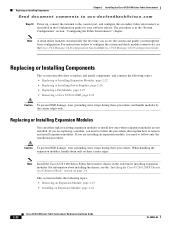
... UCS Manager GUI Configuration Guide . Replacing or Installing Components This section describes how to configure the system and check module connectivity, see the "Installing the Cisco UCS 6120XP Chassis in the Configuration guide for your software release. If you need to follow only the installation procedure. This section includes the following topics: • Replacing or Installing Expansion Modules, page 2-22 • Replacing or Installing Power Supplies, page 2-24 • Replacing a Fan Module, page 2-27 • Removing a Cisco...
... UCS Manager GUI Configuration Guide . Replacing or Installing Components This section describes how to configure the system and check module connectivity, see the "Installing the Cisco UCS 6120XP Chassis in the Configuration guide for your software release. If you need to follow only the installation procedure. This section includes the following topics: • Replacing or Installing Expansion Modules, page 2-22 • Replacing or Installing Power Supplies, page 2-24 • Replacing a Fan Module, page 2-27 • Removing a Cisco...
Hardware Installation Guide
Page 60
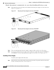
... page 2-11. 2-26 Cisco UCS 6100 Series Fabric Interconnect Hardware Installation Guide OL-20036-02 See Figure 2-14 or Figure 2-15. For ground connection instructions, see Installing a Power Supply, page 2-26. Figure 2-14 Removing the Power Supply for the Cisco UCS 6120XP Figure 2-15 Removing the Power Supply for the Cisco UCS 6140XP 273163 Step 4 Step 5 Place your right hand under the power supply to ucs-docfeedback@cisco.com Step 3 Push against...
... page 2-11. 2-26 Cisco UCS 6100 Series Fabric Interconnect Hardware Installation Guide OL-20036-02 See Figure 2-14 or Figure 2-15. For ground connection instructions, see Installing a Power Supply, page 2-26. Figure 2-14 Removing the Power Supply for the Cisco UCS 6120XP Figure 2-15 Removing the Power Supply for the Cisco UCS 6140XP 273163 Step 4 Step 5 Place your right hand under the power supply to ucs-docfeedback@cisco.com Step 3 Push against...
Hardware Installation Guide
Page 63
... rail and front rack-mount brackets do not have a stop mechanism when sliding in the "System Management" section, "Managing Blade Servers" chapter of your UCS Manager configuration as decribed in the UCS instance. Perform a backup of the UCS Manager configuration guide for your software release. The related CLI commands are: UCS-A# scope org UCS-A /org # scope service-profile service-profile-name UCS-A /org/service-profile # power down every...
... rail and front rack-mount brackets do not have a stop mechanism when sliding in the "System Management" section, "Managing Blade Servers" chapter of your UCS Manager configuration as decribed in the UCS instance. Perform a backup of the UCS Manager configuration guide for your software release. The related CLI commands are: UCS-A# scope org UCS-A /org # scope service-profile service-profile-name UCS-A /org/service-profile # power down every...

Hardware Installation Guide
Page 65
... for network connections to the Cisco UCS 6100 Series Fabric Interconnect, consider the following types of ports: • RS-232 port-create a local management connection. • Ethernet ports, encrypted and unencrypted-to connect to a LAN. • Fibre Channel ports-connect to this port to create a local management connection to set the IP address and other initial configuration settings before connecting the ports: • Cabling required for each interface type • Distance limitations for the first time. We recommend using this port must...
... for network connections to the Cisco UCS 6100 Series Fabric Interconnect, consider the following types of ports: • RS-232 port-create a local management connection. • Ethernet ports, encrypted and unencrypted-to connect to a LAN. • Fibre Channel ports-connect to this port to create a local management connection to set the IP address and other initial configuration settings before connecting the ports: • Cabling required for each interface type • Distance limitations for the first time. We recommend using this port must...

Hardware Installation Guide
Page 67
... 6100 Series Fabric Interconnect Hardware Installation Guide 3-3 Note For configuration instructions, see the Cisco UCS Manager GUI Configuration Guide. To connect the console port to a computer terminal, follow these steps: Step 1 Step 2 Configure the terminal emulator program to a computer terminal, the computer must support VT100 terminal emulation. Connecting to the Ethernet Connector Port Caution To prevent an IP address conflict, do not connect the management port to the computer serial port. Connect the RJ-45 connector of the cable to a router interface. Connect...
... 6100 Series Fabric Interconnect Hardware Installation Guide 3-3 Note For configuration instructions, see the Cisco UCS Manager GUI Configuration Guide. To connect the console port to a computer terminal, follow these steps: Step 1 Step 2 Configure the terminal emulator program to a computer terminal, the computer must support VT100 terminal emulation. Connecting to the Ethernet Connector Port Caution To prevent an IP address conflict, do not connect the management port to the computer serial port. Connect the RJ-45 connector of the cable to a router interface. Connect...

Hardware Installation Guide
Page 93
...rack 2-6, 2-8 powering up 2-20 power supply 1-14 system ground location (figure) 2-18, 2-19 Cisco UCS 6100 series description 1-1 Cisco UCS 6120XP accessory kit contents B-1 dimensions A-1 expansion modules 1-6 fan module 1-16 front view 1-3, 1-5 grounding the chassis 2-18 LEDs 1-17 port grouping 1-11 power supply 1-14 power supply LED descriptions 1-14 rear view 1-3, 1-5 removing from a rack 2-28 repacking for return 2-29 supported SFP transceivers 1-18 Cisco UCS 6140XP removing from a rack 2-28 console port connecting 3-3 Cisco UCS 6100 Series Fabric Interconnect Hardware Installation Guide...
...rack 2-6, 2-8 powering up 2-20 power supply 1-14 system ground location (figure) 2-18, 2-19 Cisco UCS 6100 series description 1-1 Cisco UCS 6120XP accessory kit contents B-1 dimensions A-1 expansion modules 1-6 fan module 1-16 front view 1-3, 1-5 grounding the chassis 2-18 LEDs 1-17 port grouping 1-11 power supply 1-14 power supply LED descriptions 1-14 rear view 1-3, 1-5 removing from a rack 2-28 repacking for return 2-29 supported SFP transceivers 1-18 Cisco UCS 6140XP removing from a rack 2-28 console port connecting 3-3 Cisco UCS 6100 Series Fabric Interconnect Hardware Installation Guide...

Hardware Installation Guide
Page 95
... SFP+ transceivers installing 3-4 installing a cable 3-5 OL-20036-02 Cisco UCS 6100 Series Fabric Interconnect Hardware Installation Guide IN-3 Index Send document comments to ucs-docfeedback@cisco.com length B-3 supported power cords (figure) B-4 supported power cords (table) B-3 power plugs B-4 power supplies blank filler panel (figure) 1-16 description 1-14, 1-15 installing 2-25 LED descriptions 1-15 removing 2-24 power supply power supply output voltage A-2 pre-installation guidelines 2-2 options 2-2 unpacking the chassis 2-6 R rack 2-6, 2-8 rack-mount installation 2-7, 2-9 rack-mount...
... SFP+ transceivers installing 3-4 installing a cable 3-5 OL-20036-02 Cisco UCS 6100 Series Fabric Interconnect Hardware Installation Guide IN-3 Index Send document comments to ucs-docfeedback@cisco.com length B-3 supported power cords (figure) B-4 supported power cords (table) B-3 power plugs B-4 power supplies blank filler panel (figure) 1-16 description 1-14, 1-15 installing 2-25 LED descriptions 1-15 removing 2-24 power supply power supply output voltage A-2 pre-installation guidelines 2-2 options 2-2 unpacking the chassis 2-6 R rack 2-6, 2-8 rack-mount installation 2-7, 2-9 rack-mount...


