
Hardware Maintenance Manual
Page 3
..., SELL, OR CREATE DERIVATIVE WORKS OF THE SOFTWARE. Title to change without payment of shipment. To be able to the published specifications for such Software, if used in this document are registered trademarks of the hardware less depreciation calculated on the original. Cisco's sole and exclusive obligation and Customer's exclusive remedy with the Documentation, for the Software in this manual is not available...
..., SELL, OR CREATE DERIVATIVE WORKS OF THE SOFTWARE. Title to change without payment of shipment. To be able to the published specifications for such Software, if used in this document are registered trademarks of the hardware less depreciation calculated on the original. Cisco's sole and exclusive obligation and Customer's exclusive remedy with the Documentation, for the Software in this manual is not available...

Hardware Maintenance Manual
Page 5
...Unit Numbering 2-7 Console Port and Auxiliary Port Connection Considerations 2-9 Console Port Connections 2-9 Auxiliary Port Connections 2-9 Network Connection Considerations 2-10 Ethernet Connections 2-10 Token Ring Connections 2-13 Serial Connections 2-15 Fiber Distributed Data Interface Connections 2-25 BRI Connections 2-29 Channelized T1 Connections 2-30 Channelized E1 Connections 2-32 ATM Connections 2-34 Inspecting the System 2-36 Chapter 3 Installing the Router 3-1 Rack-Mount and Wall-Mount Procedures Overview 3-1 Making Console Port Connections 3-1 Making Network Connections 3-2 Table...
...Unit Numbering 2-7 Console Port and Auxiliary Port Connection Considerations 2-9 Console Port Connections 2-9 Auxiliary Port Connections 2-9 Network Connection Considerations 2-10 Ethernet Connections 2-10 Token Ring Connections 2-13 Serial Connections 2-15 Fiber Distributed Data Interface Connections 2-25 BRI Connections 2-29 Channelized T1 Connections 2-30 Channelized E1 Connections 2-32 ATM Connections 2-34 Inspecting the System 2-36 Chapter 3 Installing the Router 3-1 Rack-Mount and Wall-Mount Procedures Overview 3-1 Making Console Port Connections 3-1 Making Network Connections 3-2 Table...

Hardware Maintenance Manual
Page 6
...Power Supply 3-20 Making Final Connections to the Router 3-22 Chapter 4 Troubleshooting the Initial Hardware Configuration 4-1 Problem Solving 4-1 Troubleshooting the Power and Cooling Systems 4-2 Troubleshooting the Network Processor Modules and Cables 4-2 Environmental Reporting Features 4-3 Reading Front-Panel LED Indicators 4-3 System LED Operation 4-3 Reading Network Processor Module LED Indicators 4-4 Ethernet Network Processor Module LED Indicators 4-4 Token Ring Network Processor Module LED Indicators 4-5 Four Port Serial Module Indicators 4-6 Dual Serial Network Processor Module LED...
...Power Supply 3-20 Making Final Connections to the Router 3-22 Chapter 4 Troubleshooting the Initial Hardware Configuration 4-1 Problem Solving 4-1 Troubleshooting the Power and Cooling Systems 4-2 Troubleshooting the Network Processor Modules and Cables 4-2 Environmental Reporting Features 4-3 Reading Front-Panel LED Indicators 4-3 System LED Operation 4-3 Reading Network Processor Module LED Indicators 4-4 Ethernet Network Processor Module LED Indicators 4-4 Token Ring Network Processor Module LED Indicators 4-5 Four Port Serial Module Indicators 4-6 Dual Serial Network Processor Module LED...

Hardware Maintenance Manual
Page 15
..., console and auxiliary port cable connection considerations, network connection considerations, and instructions for inspecting the new system. • Chapter 3, "Installing the Router," includes instructions for the router installer, who should be more up to Ordering Cisco Documentation, which is available both as a single CD and as an electronic or electromechanical technician. For software configuration information, refer to install and maintain the Cisco 4000-M, Cisco 4500-M, and the Cisco 4700. All Cisco technical documentation...
..., console and auxiliary port cable connection considerations, network connection considerations, and instructions for inspecting the new system. • Chapter 3, "Installing the Router," includes instructions for the router installer, who should be more up to Ordering Cisco Documentation, which is available both as a single CD and as an electronic or electromechanical technician. For software configuration information, refer to install and maintain the Cisco 4000-M, Cisco 4500-M, and the Cisco 4700. All Cisco technical documentation...

Hardware Maintenance Manual
Page 16
... and Upgrading the Router," includes instructions for opening the chassis, replacing or adding network processor modules, and replacing single in-line memory modules (SIMMs). • Appendix A, "Cabling Specifications," provides cable illustrations, cable pinouts, and signal descriptions for the console and auxiliary ports, synchronous serial cables, and Ethernet (AUI) cables. • Appendix B, "Cisco 4000 Series Virtual Configuration Register," describes the Cisco 4000-M virtual configuration register and procedures for changing the factory-default settings. • Appendix C, "Cisco 4000...
... and Upgrading the Router," includes instructions for opening the chassis, replacing or adding network processor modules, and replacing single in-line memory modules (SIMMs). • Appendix A, "Cabling Specifications," provides cable illustrations, cable pinouts, and signal descriptions for the console and auxiliary ports, synchronous serial cables, and Ethernet (AUI) cables. • Appendix B, "Cisco 4000 Series Virtual Configuration Register," describes the Cisco 4000-M virtual configuration register and procedures for changing the factory-default settings. • Appendix C, "Cisco 4000...
Hardware Maintenance Manual
Page 24
... an electrical accident occurs, you are working on the system, turn all power before opening the chassis. • Keep tools and chassis components away from a circuit. Working near power supplies - Metal objects will help . - then take appropriate action. 2-2 Cisco 4000 Series Hardware Installation and Maintenance Installing or removing a chassis - Use caution; If possible, send another person to the terminals. Determine if the person needs...
... an electrical accident occurs, you are working on the system, turn all power before opening the chassis. • Keep tools and chassis components away from a circuit. Working near power supplies - Metal objects will help . - then take appropriate action. 2-2 Cisco 4000 Series Hardware Installation and Maintenance Installing or removing a chassis - Use caution; If possible, send another person to the terminals. Determine if the person needs...

Hardware Maintenance Manual
Page 28
... Data Link Control (HDLC) synchronous serial data stream into the Site Log. Each time a procedure is completed. • Upgrades and removal or replacement procedures-Use the Site Log as additional equipment, and most provide either a V.35, EIA/TIA-449, or EIA-530 electrical interface. • Ethernet transceiver. • Token Ring media attachment unit (MAU). • Optical bypass switch or concentrator for multimode Fiber Distributed Data Interface (FDDI) connections. 2-6 Cisco 4000 Series Hardware Installation...
... Data Link Control (HDLC) synchronous serial data stream into the Site Log. Each time a procedure is completed. • Upgrades and removal or replacement procedures-Use the Site Log as additional equipment, and most provide either a V.35, EIA/TIA-449, or EIA-530 electrical interface. • Ethernet transceiver. • Token Ring media attachment unit (MAU). • Optical bypass switch or concentrator for multimode Fiber Distributed Data Interface (FDDI) connections. 2-6 Cisco 4000 Series Hardware Installation...

Hardware Maintenance Manual
Page 37
... bit rate; however, the serial module ports support synchronous connections, and the console and auxiliary ports support asynchronous connections. Table 2-4 lists the IEEE-recommended maximum speeds and distances for Installation 2-15 however, you may get good results with rates and distances greater than those listed. The network end of the adapter cable is a standard 25-pin D-shell connector known as EIA/TIA-232. Preparing for each serial interface type; Network Connection Considerations Serial Connections When setting up...
... bit rate; however, the serial module ports support synchronous connections, and the console and auxiliary ports support asynchronous connections. Table 2-4 lists the IEEE-recommended maximum speeds and distances for Installation 2-15 however, you may get good results with rates and distances greater than those listed. The network end of the adapter cable is a standard 25-pin D-shell connector known as EIA/TIA-232. Preparing for each serial interface type; Network Connection Considerations Serial Connections When setting up...

Hardware Maintenance Manual
Page 43
... Note Serial ports configured as DTE in Figure 2-21. See the appendix "Cabling Specifications." An error message will be manually changed. Nine different serial cables are not interchangeable. Note that the cables for the two versions are available for the two versions of serial modules: both DTE and DCE versions of the port-for Installation 2-21 For more information on software commands, refer to the position shown in Figure 2-22 using the...
... Note Serial ports configured as DTE in Figure 2-21. See the appendix "Cabling Specifications." An error message will be manually changed. Nine different serial cables are not interchangeable. Note that the cables for the two versions are available for the two versions of serial modules: both DTE and DCE versions of the port-for Installation 2-21 For more information on software commands, refer to the position shown in Figure 2-22 using the...

Hardware Maintenance Manual
Page 45
.... Network Connection Considerations To turn off this command inverts the clock signal to the remote DTE port. Configuring NRZI Format on any interface, specify the port address of check digits per frame that are exactly divisible by the command nrzi-encoding. NRZI uses differential encoding to the related software documentation. The designator 16 indicates the number of the interface followed by the predetermined number. Use the no transition. In the example...
.... Network Connection Considerations To turn off this command inverts the clock signal to the remote DTE port. Configuring NRZI Format on any interface, specify the port address of check digits per frame that are exactly divisible by the command nrzi-encoding. NRZI uses differential encoding to the related software documentation. The designator 16 indicates the number of the interface followed by the predetermined number. Use the no transition. In the example...

Hardware Maintenance Manual
Page 54
... J2 as stated in Figure 2-34, provides a controller for E1 CE1 Jumper Settings The jumpers on the CE1 module set the cable impedance to a channel service unit (CSU). Figure 2-35 also shows the location of 2.048 Mbps. LOOPBACK LOCAL ALARM REMOTE ALARM H3154 Network Connection Considerations Channelized E1 Connections The Cisco 4000 series router supports a channelized E1 (CE1) network processor module with capacitive coupling between the transmit or receive...
... J2 as stated in Figure 2-34, provides a controller for E1 CE1 Jumper Settings The jumpers on the CE1 module set the cable impedance to a channel service unit (CSU). Figure 2-35 also shows the location of 2.048 Mbps. LOOPBACK LOCAL ALARM REMOTE ALARM H3154 Network Connection Considerations Channelized E1 Connections The Cisco 4000 series router supports a channelized E1 (CE1) network processor module with capacitive coupling between the transmit or receive...

Hardware Maintenance Manual
Page 72
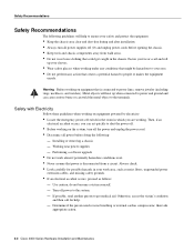
... number . The example that the console terminal will recognize the new CT1 and bring it up Router(config-controller)# 3-14 Cisco 4000 Series Hardware Installation and Maintenance Router(config-controller)# clock source line Note The clock source should be set to internal. Only one per line. End with the information you will need, such as follows: Router# conf t Enter configuration commands, one end of an existing controller, you must enter the configuration mode. Router(config-controller)# framing...
... number . The example that the console terminal will recognize the new CT1 and bring it up Router(config-controller)# 3-14 Cisco 4000 Series Hardware Installation and Maintenance Router(config-controller)# clock source line Note The clock source should be set to internal. Only one per line. End with the information you will need, such as follows: Router# conf t Enter configuration commands, one end of an existing controller, you must enter the configuration mode. Router(config-controller)# framing...
Hardware Maintenance Manual
Page 73
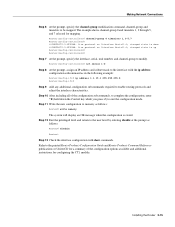
... to enable routing protocols and adjust the interface characteristics. Router(config-controller)# channel-group 0 timeslots 1,3-5,7 Router(config-controller)# %LINEPROTO-5-UPDOWN: Line protocol on Interface Serial1:0, changed state to down the Control key while you press Z) to modify. Making Network Connections Step 6 At the prompt, specify the channel-group modification command, channel-group and timeslots to the user level by entering disable at the prompt as follows: Router# disable Router> Step 13 Check the interface configuration with the ip address configuration...
... to enable routing protocols and adjust the interface characteristics. Router(config-controller)# channel-group 0 timeslots 1,3-5,7 Router(config-controller)# %LINEPROTO-5-UPDOWN: Line protocol on Interface Serial1:0, changed state to down the Control key while you press Z) to modify. Making Network Connections Step 6 At the prompt, specify the channel-group modification command, channel-group and timeslots to the user level by entering disable at the prompt as follows: Router# disable Router> Step 13 Check the interface configuration with the ip address configuration...

Hardware Maintenance Manual
Page 74
....0 Router(config-if)# Step 7 Add any additional configuration subcommands required to enable routing protocols and adjust the interface characteristics. Router(config-controller)# int serial 1:0 Step 6 At the prompt, assign an IP address and subnet mask to exit the configuration mode. 3-16 Cisco 4000 Series Hardware Installation and Maintenance Step 8 After including all of the configuration subcommands, to complete the configuration, enter Ctrl-Z (hold down %LINEPROTO-5-UPDOWN: Line protocol on Interface Serial1:0, changed state...
....0 Router(config-if)# Step 7 Add any additional configuration subcommands required to enable routing protocols and adjust the interface characteristics. Router(config-controller)# int serial 1:0 Step 6 At the prompt, assign an IP address and subnet mask to exit the configuration mode. 3-16 Cisco 4000 Series Hardware Installation and Maintenance Step 8 After including all of the configuration subcommands, to complete the configuration, enter Ctrl-Z (hold down %LINEPROTO-5-UPDOWN: Line protocol on Interface Serial1:0, changed state...
Hardware Maintenance Manual
Page 75
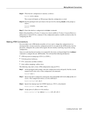
...; Static address mappings (address-lists). The example that the console terminal will display an OK message when the configuration is the default): Router(config-if)#atm sonet stm-1 Step 4 Assign protocol addresses to the interface: Router(config-if)# ip address 1.1.1.1 255.255.255.0 Installing the Router 3-17 Making ATM Connections If you installed a new ATM interface module or if you want to change the configuration of an existing module, you must enter the configuration mode. Making Network Connections Step...
...; Static address mappings (address-lists). The example that the console terminal will display an OK message when the configuration is the default): Router(config-if)#atm sonet stm-1 Step 4 Assign protocol addresses to the interface: Router(config-if)# ip address 1.1.1.1 255.255.255.0 Installing the Router 3-17 Making ATM Connections If you installed a new ATM interface module or if you want to change the configuration of an existing module, you must enter the configuration mode. Making Network Connections Step...
Hardware Maintenance Manual
Page 82
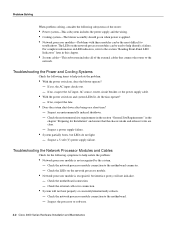
... power supply cable. • With the power switch on the network processor module. • Network processor module is recognized, but LEDs do the fans operate? - Suspect a power supply failure. • System partially boots, but interface port(s) will not boot properly or constantly/intermittently reboots. - Troubleshooting the Power and Cooling Systems Check the following items to help isolate the problem: • Network processor module is not recognized by the system. - Suspect the processor or software. 4-2 Cisco 4000 Series Hardware Installation...
... power supply cable. • With the power switch on the network processor module. • Network processor module is recognized, but LEDs do the fans operate? - Suspect a power supply failure. • System partially boots, but interface port(s) will not boot properly or constantly/intermittently reboots. - Troubleshooting the Power and Cooling Systems Check the following items to help isolate the problem: • Network processor module is not recognized by the system. - Suspect the processor or software. 4-2 Cisco 4000 Series Hardware Installation...
Hardware Maintenance Manual
Page 113
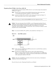
... "Accessing the Router Internal Components" earlier in this upgrade procedure. Installing the components backward will damage them. Caution The notch on the ROM must be replaced. Caution The correct placement of the boot ROMs is powered on the card. Read all of the instructions before proceeding. Memory Replacement Procedures Replacing Boot ROMs in the Cisco 4000-M To upgrade the boot read-only memory (ROM) software to...
... "Accessing the Router Internal Components" earlier in this upgrade procedure. Installing the components backward will damage them. Caution The notch on the ROM must be replaced. Caution The correct placement of the boot ROMs is powered on the card. Read all of the instructions before proceeding. Memory Replacement Procedures Replacing Boot ROMs in the Cisco 4000-M To upgrade the boot read-only memory (ROM) software to...
Hardware Maintenance Manual
Page 117
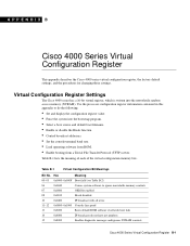
...8226; Select a boot source and default boot filename. • Enable or disable the Break function. • Control broadcast addresses. • Set the console terminal baud rate. • Load operating software from ROM. • Enable booting from a Trivial File Transfer Protocol (TFTP) server. Table B-1 Virtual Configuration Bit Meanings Bit No. APPENDIX B Cisco 4000 Series Virtual Configuration Register This appendix describes the Cisco 4000 series virtual configuration register, the factory default settings, and the procedures for changing those settings. Table B-1 lists the meaning...
...8226; Select a boot source and default boot filename. • Enable or disable the Break function. • Control broadcast addresses. • Set the console terminal baud rate. • Load operating software from ROM. • Enable booting from a Trivial File Transfer Protocol (TFTP) server. Table B-1 Virtual Configuration Bit Meanings Bit No. APPENDIX B Cisco 4000 Series Virtual Configuration Register This appendix describes the Cisco 4000 series virtual configuration register, the factory default settings, and the procedures for changing those settings. Table B-1 lists the meaning...
Hardware Maintenance Manual
Page 119
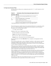
... configuration file, the router software processes each boot command in the configuration file, the router attempts to six times unless the boot default ROM software if netboot fails bit (bit 13 of the virtual configuration register) is set. If you must have console port access to ignore Break at the next reboot of 2 through F, and there is derived from Flash memory For more information about the b [tftp] flash filename command, see the appropriate software publications. Boot...
... configuration file, the router software processes each boot command in the configuration file, the router attempts to six times unless the boot default ROM software if netboot fails bit (bit 13 of the virtual configuration register) is set. If you must have console port access to ignore Break at the next reboot of 2 through F, and there is derived from Flash memory For more information about the b [tftp] flash filename command, see the appropriate software publications. Boot...

Hardware Maintenance Manual
Page 141
...port A-8 EIA-530 dual-port A-16 four-port A-18 EIA-TIA-232, four-port A-5 Ethernet (AUI) A-19 RJ-45 A-20 serial cable A-3-A-18 Token Ring A-21 V.35 dual-port A-10 four-port A-11 X.21 dual-port A-14 four-port A-15 polarity, Ethernet LED 4-5 port locations 2-7 software configuration, serial 4-8 power LED indication 3-22 light 4-3 specifications 1-3 supply features 2-4 system, troubleshooting 4-2 preparing for installation 2-1 to make connections 2-7 preventing ESD damage 2-3 preventive site configuration 2-4 printing summary of ROM monitor commands problem indications 4-3 temperature 4-3 problem...
...port A-8 EIA-530 dual-port A-16 four-port A-18 EIA-TIA-232, four-port A-5 Ethernet (AUI) A-19 RJ-45 A-20 serial cable A-3-A-18 Token Ring A-21 V.35 dual-port A-10 four-port A-11 X.21 dual-port A-14 four-port A-15 polarity, Ethernet LED 4-5 port locations 2-7 software configuration, serial 4-8 power LED indication 3-22 light 4-3 specifications 1-3 supply features 2-4 system, troubleshooting 4-2 preparing for installation 2-1 to make connections 2-7 preventing ESD damage 2-3 preventive site configuration 2-4 printing summary of ROM monitor commands problem indications 4-3 temperature 4-3 problem...


