
Installation Guide
Page 5
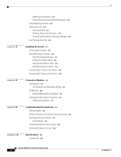
... Documentation and Submitting a Service Request xxi Product Overview 1-1 Catalyst 4900 Series Switch Applications 1-2 Catalyst 4948 Switch Software Features 1-3 Catalyst 4948-10GE and Catalyst 4928-10GE Switch Software Features 1-4 Hardware System Features 1-6 Switch Components 1-7 Traffic Ports on the Catalyst 4948 1-7 Traffic Ports on the Catalyst 4948-10GE 1-7 Traffic Ports on the Catalyst 4928-10GE 1-7 Console Port 1-7 Front Panel LEDs 1-9 Chassis Cooling 1-11 Power Supplies 1-12 Environmental Monitoring of the Power Supplies 1-13 Power Management for the Switch 1-14 Power Management Modes...
... Documentation and Submitting a Service Request xxi Product Overview 1-1 Catalyst 4900 Series Switch Applications 1-2 Catalyst 4948 Switch Software Features 1-3 Catalyst 4948-10GE and Catalyst 4928-10GE Switch Software Features 1-4 Hardware System Features 1-6 Switch Components 1-7 Traffic Ports on the Catalyst 4948 1-7 Traffic Ports on the Catalyst 4948-10GE 1-7 Traffic Ports on the Catalyst 4928-10GE 1-7 Console Port 1-7 Front Panel LEDs 1-9 Chassis Cooling 1-11 Power Supplies 1-12 Environmental Monitoring of the Power Supplies 1-13 Power Management for the Switch 1-14 Power Management Modes...
Installation Guide
Page 6
...Tools 3-5 Rack-Mounting the Switch 3-6 Connecting AC Power to the Switch 3-9 Connecting DC Power to the Switch 3-11 Transceiver Modules 4-1 SFP Modules 4-1 SFP Modules and Alternative Wiring 4-1 X2 Modules 4-2 Module Maintenance Guidelines 4-5 Cleaning the Fiber-Optic Connectors 4-5 Additional Guidelines 4-7 Troubleshooting the Installation 5-1 Getting Started 5-2 Problem Solving to the System Component Level 5-2 Identifying Startup Problems 5-3 LED Readings 5-3 Troubleshooting the Power Supply 5-5 Contacting Customer Service 5-6 Specifications A-1 Console Port A-1 Catalyst 4900 Series Switch...
...Tools 3-5 Rack-Mounting the Switch 3-6 Connecting AC Power to the Switch 3-9 Connecting DC Power to the Switch 3-11 Transceiver Modules 4-1 SFP Modules 4-1 SFP Modules and Alternative Wiring 4-1 X2 Modules 4-2 Module Maintenance Guidelines 4-5 Cleaning the Fiber-Optic Connectors 4-5 Additional Guidelines 4-7 Troubleshooting the Installation 5-1 Getting Started 5-2 Problem Solving to the System Component Level 5-2 Identifying Startup Problems 5-3 LED Readings 5-3 Troubleshooting the Power Supply 5-5 Contacting Customer Service 5-6 Specifications A-1 Console Port A-1 Catalyst 4900 Series Switch...
Installation Guide
Page 7
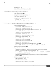
... P E N D I X Management Port A-2 Catalyst 4900 Series Switch Specifications A-3 Initial Configuration for the Switch B-1 Connecting to the Switch B-2 Starting the Terminal-Emulation Software B-3 Connecting to a Power Source B-3 Entering the Initial Configuration Information B-4 IP Settings B-4 Performing the Initial Configuration B-5 Compliance Information and Translated Safety Warnings C-1 Translated Safety Warnings C-2 Statement 1003-DC Power Disconnection C-2 Statement 1004-Installation Instructions C-4 Statement 1006-Chassis Warning for Rack-Mounting and Servicing C-6 Statement 1008-Class...
... P E N D I X Management Port A-2 Catalyst 4900 Series Switch Specifications A-3 Initial Configuration for the Switch B-1 Connecting to the Switch B-2 Starting the Terminal-Emulation Software B-3 Connecting to a Power Source B-3 Entering the Initial Configuration Information B-4 IP Settings B-4 Performing the Initial Configuration B-5 Compliance Information and Translated Safety Warnings C-1 Translated Safety Warnings C-2 Statement 1003-DC Power Disconnection C-2 Statement 1004-Installation Instructions C-4 Statement 1006-Chassis Warning for Rack-Mounting and Servicing C-6 Statement 1008-Class...
Installation Guide
Page 10
... for the Switch configuration via Telnet. Refer to help isolate and resolve problems. Specifications Lists the switch system specifications. Compliance Information and Translated Safety Warnings States compliance information for the initial hardware Installation installation and suggests steps to the version of a system that also runs on the Catalyst 4500 series switches. Initial Configuration Details initial setup of these documents appropriate for your software release: • Catalyst 4500 Series Switch Cisco IOS Software Configuration Guide http://www.cisco.com/en...
... for the Switch configuration via Telnet. Refer to help isolate and resolve problems. Specifications Lists the switch system specifications. Compliance Information and Translated Safety Warnings States compliance information for the initial hardware Installation installation and suggests steps to the version of a system that also runs on the Catalyst 4500 series switches. Initial Configuration Details initial setup of these documents appropriate for your software release: • Catalyst 4500 Series Switch Cisco IOS Software Configuration Guide http://www.cisco.com/en...
Installation Guide
Page 24
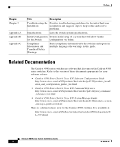
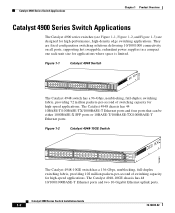
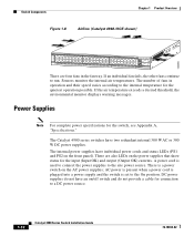
.../1000 connectivity on all ports, supporting hot swappable, redundant power supplies in a compact one rack-unit size for applications where space is limited. Figure 1-2 Catalyst 4948-10GE Switch 130083 PS1 PS2 FAN STATUS 1 16 17 32 33 Catalyst WS-C4948 10GE X2-1 X2-2 CON 48 MGT The Catalyst 4948-10GE switch has a 136-Gbps, nonblocking, full-duplex switching fabric, providing 102 million packets-per -second of switching capacity for high-speed applications. The Catalyst 4948...
.../1000 connectivity on all ports, supporting hot swappable, redundant power supplies in a compact one rack-unit size for applications where space is limited. Figure 1-2 Catalyst 4948-10GE Switch 130083 PS1 PS2 FAN STATUS 1 16 17 32 33 Catalyst WS-C4948 10GE X2-1 X2-2 CON 48 MGT The Catalyst 4948-10GE switch has a 136-Gbps, nonblocking, full-duplex switching fabric, providing 102 million packets-per -second of switching capacity for high-speed applications. The Catalyst 4948...

Installation Guide
Page 25
...,768 MAC addresses for Layer 2 switching • Support for the switch. All three switches have a removable automatic variable speed fan tray for low noise operation at room temperature and removable and redundant 300 W AC or 300 W DC power supply provides fault-tolerance protection for 2,048 VLANs and 4,096 VLAN IDs - Catalyst 4948 Switch Software Features The following is an overview of switching capacity for Gigabit EtherChannel 78-18039-02 Catalyst 4900 Series Switch Installation Guide 1-3 Q-in...
...,768 MAC addresses for Layer 2 switching • Support for the switch. All three switches have a removable automatic variable speed fan tray for low noise operation at room temperature and removable and redundant 300 W AC or 300 W DC power supply provides fault-tolerance protection for 2,048 VLANs and 4,096 VLAN IDs - Catalyst 4948 Switch Software Features The following is an overview of switching capacity for Gigabit EtherChannel 78-18039-02 Catalyst 4900 Series Switch Installation Guide 1-3 Q-in...
Installation Guide
Page 26
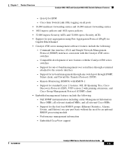
... Spanning Tree, Cisco Discovery Protocol (CDP), VTP version 2 with the Catalyst 4500 series switches - Performance management information - Support for an optional RMON processing module - Command-line interface (CLI) and Simple Network Management Protocol (SNMP) interfaces consistent with pruning extensions, and Cisco Group Management Protocol (CGMP) client • Embedded management features include the following is an overview of -band management over serial lines through SNMP, Telnet client, and Trivial File Transfer Protocol (TFTP) - IEEE 802.1Q VLAN tagging on a per-port...
... Spanning Tree, Cisco Discovery Protocol (CDP), VTP version 2 with the Catalyst 4500 series switches - Performance management information - Support for an optional RMON processing module - Command-line interface (CLI) and Simple Network Management Protocol (SNMP) interfaces consistent with pruning extensions, and Cisco Group Management Protocol (CGMP) client • Embedded management features include the following is an overview of -band management over serial lines through SNMP, Telnet client, and Trivial File Transfer Protocol (TFTP) - IEEE 802.1Q VLAN tagging on a per-port...
Installation Guide
Page 27
... SNMP, Telnet client, and Trivial File Transfer Protocol (TFTP) - Remote Monitoring (RMON) with the Catalyst 4500 series switches - Chapter 1 Product Overview Catalyst 4948-10GE and Catalyst 4928-10GE Switch Software Features - Command-line interface (CLI) and Simple Network Management Protocol (SNMP) interfaces consistent with RMON-1 - Q-in -band management through any switch port through a terminal attached to the console interface - Support for the first four RMON groups (Ethernet Statistics, Alarms, Events, and History) on all relevant Cisco MIBs - Cisco Inter Switch Link...
... SNMP, Telnet client, and Trivial File Transfer Protocol (TFTP) - Remote Monitoring (RMON) with the Catalyst 4500 series switches - Chapter 1 Product Overview Catalyst 4948-10GE and Catalyst 4928-10GE Switch Software Features - Command-line interface (CLI) and Simple Network Management Protocol (SNMP) interfaces consistent with RMON-1 - Q-in -band management through any switch port through a terminal attached to the console interface - Support for the first four RMON groups (Ethernet Statistics, Alarms, Events, and History) on all relevant Cisco MIBs - Cisco Inter Switch Link...
Installation Guide
Page 28
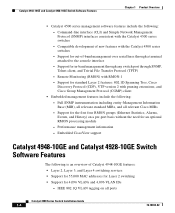
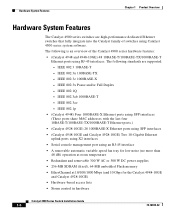
... 48 dB) operation at room temperature • Redundant and removable 300 W AC or 300 W DC power supplies • 256-MB SDRAM (fixed), 64-MB embedded Flash memory • EtherChannel at 10/100/1000 Mbps (and 10 Gbps for the Catalyst 4948-10GE and Catalyst 4928-10GE) • Hardware-based access lists • Storm control in hardware Catalyst 4900 Series Switch Installation Guide 1-6 78-18039-02 IEEE 802.3 10BASE-T -
... 48 dB) operation at room temperature • Redundant and removable 300 W AC or 300 W DC power supplies • 256-MB SDRAM (fixed), 64-MB embedded Flash memory • EtherChannel at 10/100/1000 Mbps (and 10 Gbps for the Catalyst 4948-10GE and Catalyst 4928-10GE) • Hardware-based access lists • Storm control in hardware Catalyst 4900 Series Switch Installation Guide 1-6 78-18039-02 IEEE 802.3 10BASE-T -
Installation Guide
Page 29
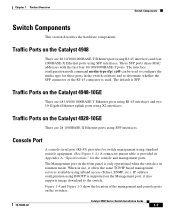
...Ethernet uplink ports using SFP interfaces. IP address configuration using inband access (Telnet, SNMP, etc.). These SFP ports share MAC addresses with the last four 10/100/1000BASE-T ports. Traffic Ports on the Catalyst 4948-10GE There are 48 10/100/1000BASE-T Ethernet ports using RJ-45 interfaces and four 1000BASE-X Ethernet ports using standard console equipment. (See Figure 1-4.) A connector pinout table is provided in Appendix A, "Specifications," for these ports in rommon mode. The interface configuration mode command media-type sfp | rj45 can be used . The Management port...
...Ethernet uplink ports using SFP interfaces. IP address configuration using inband access (Telnet, SNMP, etc.). These SFP ports share MAC addresses with the last four 10/100/1000BASE-T ports. Traffic Ports on the Catalyst 4948-10GE There are 48 10/100/1000BASE-T Ethernet ports using RJ-45 interfaces and four 1000BASE-X Ethernet ports using standard console equipment. (See Figure 1-4.) A connector pinout table is provided in Appendix A, "Specifications," for these ports in rommon mode. The interface configuration mode command media-type sfp | rj45 can be used . The Management port...
Installation Guide
Page 32
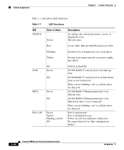
.... Table 1-1 LED Functions LED STATUS Color or State Green Description At startup, the switch performs a series of diagnostic tests: All tests pass Red A test other than an individual port test fails Flashing System boot or diagnostic tests in progress Yellow System is in rommon mode or a power supply has failed CON MGT Port 1-48 Off Green Off Green Off Green Yellow Flashing yellow Off Switch is disabled 10/100 BASE-T console port is in link...
.... Table 1-1 LED Functions LED STATUS Color or State Green Description At startup, the switch performs a series of diagnostic tests: All tests pass Red A test other than an individual port test fails Flashing System boot or diagnostic tests in progress Yellow System is in rommon mode or a power supply has failed CON MGT Port 1-48 Off Green Off Green Off Green Yellow Flashing yellow Off Switch is disabled 10/100 BASE-T console port is in link...
Installation Guide
Page 34
The number of fans in the fan tray. Power Supplies Note For complete power specifications for the switch, see Appendix A, "Specifications." A power cord is set to the On position. If the air temperature exceeds a desired threshold, the environmental monitor displays warning messages. DC power supplies do not provide a cable for connection to run. If an individual fan fails, the other fans continue to a DC power source. 1-12 Catalyst 4900 Series Switch Installation Guide 78-18039-02...
The number of fans in the fan tray. Power Supplies Note For complete power specifications for the switch, see Appendix A, "Specifications." A power cord is set to the On position. If the air temperature exceeds a desired threshold, the environmental monitor displays warning messages. DC power supplies do not provide a cable for connection to run. If an individual fan fails, the other fans continue to a DC power source. 1-12 Catalyst 4900 Series Switch Installation Guide 78-18039-02...
Installation Guide
Page 61
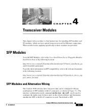
...://www.cisco.com/en/US/products/hw/modules/ps5455/products_device_sup port_tables_list.html SFP Modules and Alternative Wiring The Catalyst 4948 switches have four ports that can be configured with any combination of SFP modules with LC connectors, as shown in the switch software and determines whether the SFP or the RJ-45 connector is SFP. 78-18039-02 Catalyst 4900 Series Switch Installation Guide 4-1 The default is used for Ethernet connections. Where needed, notes applying specifically...
...://www.cisco.com/en/US/products/hw/modules/ps5455/products_device_sup port_tables_list.html SFP Modules and Alternative Wiring The Catalyst 4948 switches have four ports that can be configured with any combination of SFP modules with LC connectors, as shown in the switch software and determines whether the SFP or the RJ-45 connector is SFP. 78-18039-02 Catalyst 4900 Series Switch Installation Guide 4-1 The default is used for Ethernet connections. Where needed, notes applying specifically...
Installation Guide
Page 73
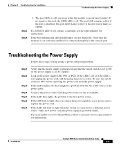
... power supply is OFF before removing the power cord from the power supply. If the boot information and system banner are green when the module is available. If the LED remains off switch is set correctly and that it is connected properly to a new power source, replace the power cord. If no signal is detected, the LINK LED is red, contact a customer service representative for instructions. 78-18039-02 Catalyst 4900 Series Switch Installation Guide...
... power supply is OFF before removing the power cord from the power supply. If the boot information and system banner are green when the module is available. If the LED remains off switch is set correctly and that it is connected properly to a new power source, replace the power cord. If no signal is detected, the LINK LED is red, contact a customer service representative for instructions. 78-18039-02 Catalyst 4900 Series Switch Installation Guide...
Installation Guide
Page 75
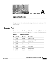
... output output - - The Request to Send (RTS) signal tracks the state of the Clear to send data terminal ready transmit data - - input input input Description request to Send (CTS) input. receive data data set ready clear to send 78-18039-02 Catalyst 4900 Series Switch Installation Guide A-1 Specifications A A P P E N D I X This appendix provides cable and technical specifications for the Catalyst 4900 series switches. Table A-1 lists the console port pinouts. Console Port The console port is an RJ-45 receptacle.
... output output - - The Request to Send (RTS) signal tracks the state of the Clear to send data terminal ready transmit data - - input input input Description request to Send (CTS) input. receive data data set ready clear to send 78-18039-02 Catalyst 4900 Series Switch Installation Guide A-1 Specifications A A P P E N D I X This appendix provides cable and technical specifications for the Catalyst 4900 series switches. Table A-1 lists the console port pinouts. Console Port The console port is an RJ-45 receptacle.
Installation Guide
Page 81
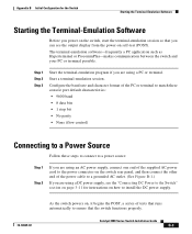
... are using a PC or terminal. Start a terminal-emulation session. Appendix B Initial Configuration for instructions on how to install the DC power supply. 78-18039-02 As the switch powers on self-test (POST). Configure the baud rate and character format of the PC or terminal to match these console port default characteristics: • 9600 baud • 8 data bits • 1 stop bit • No parity • None (flow control) Connecting to a Power...
... are using a PC or terminal. Start a terminal-emulation session. Appendix B Initial Configuration for instructions on how to install the DC power supply. 78-18039-02 As the switch powers on self-test (POST). Configure the baud rate and character format of the PC or terminal to match these console port default characteristics: • 9600 baud • 8 data bits • 1 stop bit • No parity • None (flow control) Connecting to a Power...
Installation Guide
Page 82
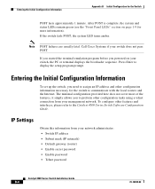
... your network administrator: • Switch IP address • Subnet mask (IP netmask) • Default gateway (router) • Enable secret password • Enable password • Telnet password Catalyst 4900 Series Switch Installation Guide B-4 78-18039-02 Call Cisco Systems if your management network. Entering the Initial Configuration Information To set up the switch, you need to assign an IP address and other features and interfaces, please refer to preform other configuration tasks using a telnet connection from your switch, the PC or terminal displays...
... your network administrator: • Switch IP address • Subnet mask (IP netmask) • Default gateway (router) • Enable secret password • Enable password • Telnet password Catalyst 4900 Series Switch Installation Guide B-4 78-18039-02 Call Cisco Systems if your management network. Entering the Initial Configuration Information To set up the switch, you need to assign an IP address and other features and interfaces, please refer to preform other configuration tasks using a telnet connection from your switch, the PC or terminal displays...

Installation Guide
Page 83
..., CA c or Switch1 (config)# banner motd c 170 West Tasman Drive, San Jose, CA; Switch# configure terminal Enter configuration commands, one per line. To remove the new prompt and return the prompt to its default, use the no prompt command. Switch# show clock command. Tech Support 408 123 4567 c Configure an enable secret password, and press Return. 78-18039-02 Catalyst 4900 Series Switch Installation Guide B-5 End with CNTL/Z. Switch# clock set 20:09:01...
..., CA c or Switch1 (config)# banner motd c 170 West Tasman Drive, San Jose, CA; Switch# configure terminal Enter configuration commands, one per line. To remove the new prompt and return the prompt to its default, use the no prompt command. Switch# show clock command. Tech Support 408 123 4567 c Configure an enable secret password, and press Return. 78-18039-02 Catalyst 4900 Series Switch Installation Guide B-5 End with CNTL/Z. Switch# clock set 20:09:01...
Installation Guide
Page 84
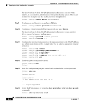
...# show ip route commands. Output suppressed. Entering the Initial Configuration Information Appendix B Initial Configuration for the Switch The password can start with a number, is case sensitive, allows spaces, but ignores leading spaces. The secret password is encrypted and the enable password is in plain text. banner motd ^C 170 West Tasman Drive, San Jose, CA ^C ! !--- Switch1# show ip interface brief Catalyst 4900 Series Switch Installation Guide B-6 78...
...# show ip route commands. Output suppressed. Entering the Initial Configuration Information Appendix B Initial Configuration for the Switch The password can start with a number, is case sensitive, allows spaces, but ignores leading spaces. The secret password is encrypted and the enable password is in plain text. banner motd ^C 170 West Tasman Drive, San Jose, CA ^C ! !--- Switch1# show ip interface brief Catalyst 4900 Series Switch Installation Guide B-6 78...
Installation Guide
Page 85
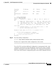
... switch software configuration guide or the switch command reference. 78-18039-02 Catalyst 4900 Series Switch Installation Guide B-7 OSPF NSSA external type 1, N2 - To use the CLI to perform additional configuration or management tasks, enter commands at the Switch> prompt through the console port by using a terminal program or through the network by using Telnet. OSPF inter area N1 - Method YES manual YES unset Status up up IP-Address 172.16.1.2 unassigned OK? mobile, B BGP D - ISIS level-1, L2 - per-user static route...
... switch software configuration guide or the switch command reference. 78-18039-02 Catalyst 4900 Series Switch Installation Guide B-7 OSPF NSSA external type 1, N2 - To use the CLI to perform additional configuration or management tasks, enter commands at the Switch> prompt through the console port by using a terminal program or through the network by using Telnet. OSPF inter area N1 - Method YES manual YES unset Status up up IP-Address 172.16.1.2 unassigned OK? mobile, B BGP D - ISIS level-1, L2 - per-user static route...


