Hardware Installation Guide
Page 17
...hardware features of the Catalyst 3750 family of each switch, explains how to configure your switch. For information about the standard Cisco IOS Release 12.1 commands, refer to the switch software configuration guide, the switch command reference, and the switch system message guide on ...the Cisco.com Product Documentation home page. For more information, refer to the IOS documentation set from the Cisco IOS Software drop-down list. 78-15136-02 Catalyst 3750 Switch Hardware Installation Guide xv We assume that...
...hardware features of the Catalyst 3750 family of each switch, explains how to configure your switch. For information about the standard Cisco IOS Release 12.1 commands, refer to the switch software configuration guide, the switch command reference, and the switch system message guide on ...the Cisco.com Product Documentation home page. For more information, refer to the IOS documentation set from the Cisco IOS Software drop-down list. 78-15136-02 Catalyst 3750 Switch Hardware Installation Guide xv We assume that...
Hardware Installation Guide
Page 26
... case by telephone. If your issue is not resolved using these recommendations, your case will commit all the tools on the Cisco TAC website requires a Cisco.com user ID and password. If you require product information). Obtaining Technical Assistance Preface Accessing all necessary resources around the clock...Asia-Pacific: +61 2 8446 7411 (Australia: 1 800 805 227) EMEA: +32 2 704 55 55 USA: 1 800 553-2447 For a complete listing of Cisco TAC contacts, go to help keep your business operations running smoothly. xxiv Catalyst 3750 Switch Hardware Installation Guide 78-15136-02
... case by telephone. If your issue is not resolved using these recommendations, your case will commit all the tools on the Cisco TAC website requires a Cisco.com user ID and password. If you require product information). Obtaining Technical Assistance Preface Accessing all necessary resources around the clock...Asia-Pacific: +61 2 8446 7411 (Australia: 1 800 805 227) EMEA: +32 2 704 55 55 USA: 1 800 553-2447 For a complete listing of Cisco TAC contacts, go to help keep your business operations running smoothly. xxiv Catalyst 3750 Switch Hardware Installation Guide 78-15136-02
Hardware Installation Guide
Page 28
... in designing, developing, and operating public and private internets and intranets. Obtaining Additional Publications and Information Preface • iQ Magazine is a quarterly journal published by Cisco Systems for engineering professionals involved in network training are listed at this URL: http://www.cisco.com/en/US/about Internet business strategies for executives.
... in designing, developing, and operating public and private internets and intranets. Obtaining Additional Publications and Information Preface • iQ Magazine is a quarterly journal published by Cisco Systems for engineering professionals involved in network training are listed at this URL: http://www.cisco.com/en/US/about Internet business strategies for executives.

Hardware Installation Guide
Page 47
...-optic SFP module. Chapter 2 Product Overview Front Panel Description SFP Module Slots The SFP module slots support the SFP modules listed in an SFP module slot. The Catalyst 3750 models support these Cisco SFP options: • 1000BASE-LX • 1000BASE-SX • 1000BASE-T For more information about these SFP modules, refer to...
...-optic SFP module. Chapter 2 Product Overview Front Panel Description SFP Module Slots The SFP module slots support the SFP modules listed in an SFP module slot. The Catalyst 3750 models support these Cisco SFP options: • 1000BASE-LX • 1000BASE-SX • 1000BASE-T For more information about these SFP modules, refer to...

Hardware Installation Guide
Page 49
... If it is in standby mode or in a switch has failed, and the RPS is connected and ready to a neighboring device). Contact Cisco Systems. The internal power supply in a fault condition. System is receiving power but is unavailable because it does not, the RPS fan could ...properly connected. The RPS is providing power to another device (redundancy has been allocated to provide back-up power, if required. Table 2-2 lists the LED colors and their meanings. System is functioning properly. Chapter 2 Product Overview Front Panel Description System LED The System LED shows ...
... If it is in standby mode or in a switch has failed, and the RPS is connected and ready to a neighboring device). Contact Cisco Systems. The internal power supply in a fault condition. System is receiving power but is unavailable because it does not, the RPS fan could ...properly connected. The RPS is providing power to another device (redundancy has been allocated to provide back-up power, if required. Table 2-2 lists the LED colors and their meanings. System is functioning properly. Chapter 2 Product Overview Front Panel Description System LED The System LED shows ...

Hardware Installation Guide
Page 50
...port mode and meaning. Table 2-3 Master LED Port Mode Off Green Amber Description Switch is the stack master or a standalone switch. Table 2-4 lists the mode LEDs and their meanings. Table 2-5 explains how to interpret the port LED colors in the stack also display SPEED. 2-10 Catalyst... of the switches in the stack, all the other switches in different port modes. For more information about the Cisco RPS 300, refer to the Cisco RPS 300 Redundant Power System Hardware Installation Guide. Front Panel Description Chapter 2 Product Overview For more information about the...
...port mode and meaning. Table 2-3 Master LED Port Mode Off Green Amber Description Switch is the stack master or a standalone switch. Table 2-4 lists the mode LEDs and their meanings. Table 2-5 explains how to interpret the port LED colors in the stack also display SPEED. 2-10 Catalyst... of the switches in the stack, all the other switches in different port modes. For more information about the Cisco RPS 300, refer to the Cisco RPS 300 Redundant Power System Hardware Installation Guide. Front Panel Description Chapter 2 Product Overview For more information about the...

Hardware Installation Guide
Page 66
...you must not exceed the stipulated cable length for link distances greater than 984 feet (300 m). • Operating environment is within the ranges listed in an elevated bit error rate (BER). Front-panel indicators can cause transceiver saturation, resulting in Appendix A, "Technical Specifications." • Clearance ...SFP module and the MMF cable on the other end of the link. Access to 328 feet (100 meters). • Table 3-1 lists the cable specifications for 1000BASE-SX and 1000BASE-LX fiber-optic SFP connections. Catalyst 3750 Switch Hardware Installation Guide 3-6 78-15136-02 ...
...you must not exceed the stipulated cable length for link distances greater than 984 feet (300 m). • Operating environment is within the ranges listed in an elevated bit error rate (BER). Front-panel indicators can cause transceiver saturation, resulting in Appendix A, "Technical Specifications." • Clearance ...SFP module and the MMF cable on the other end of the link. Access to 328 feet (100 meters). • Table 3-1 lists the cable specifications for 1000BASE-SX and 1000BASE-LX fiber-optic SFP connections. Catalyst 3750 Switch Hardware Installation Guide 3-6 78-15136-02 ...

Hardware Installation Guide
Page 100
...Removing SFP Modules These sections describe how to identify and validate that the SFP module meets the requirements for the list of the Catalyst 3750 switches. Use only Cisco SFP modules on the other end of the cable, and the cable must match the wave-length specifications on ...the Catalyst 3750 switch. This encoding provides a way for Cisco to install and remove SFP modules. Installing and Removing SFP Modules Chapter 3 Switch Installation Figure 3-36 Incorrect Removal of SFP modules. See the...
...Removing SFP Modules These sections describe how to identify and validate that the SFP module meets the requirements for the list of the Catalyst 3750 switches. Use only Cisco SFP modules on the other end of the cable, and the cable must match the wave-length specifications on ...the Catalyst 3750 switch. This encoding provides a way for Cisco to install and remove SFP modules. Installing and Removing SFP Modules Chapter 3 Switch Installation Figure 3-36 Incorrect Removal of SFP modules. See the...

Hardware Installation Guide
Page 119
A A P P E N D I X Technical Specifications This appendix lists the switch technical specifications in Table A-2, Table A-3, Table A-4, Table A-5, and the regulatory agency approvals in Table A-6. Table A-1 Specifications for the Catalyst 3750G-12S Switch Environmental ...
A A P P E N D I X Technical Specifications This appendix lists the switch technical specifications in Table A-2, Table A-3, Table A-4, Table A-5, and the regulatory agency approvals in Table A-6. Table A-1 Specifications for the Catalyst 3750G-12S Switch Environmental ...

Hardware Installation Guide
Page 129
... for fiber-optic and copper uplink ports. Appendix B Connector and Cable Specifications Connector Specifications SFP Module Ports The Catalyst 3750 switch uses SFP modules for a list of supported SFP modules. Figure B-3 Fiber-Optic SFP Module LC Connector 58476 Warning Invisible laser radiation may be emitted from disconnected fibers or connectors. Do...
... for fiber-optic and copper uplink ports. Appendix B Connector and Cable Specifications Connector Specifications SFP Module Ports The Catalyst 3750 switch uses SFP modules for a list of supported SFP modules. Figure B-3 Fiber-Optic SFP Module LC Connector 58476 Warning Invisible laser radiation may be emitted from disconnected fibers or connectors. Do...
Hardware Installation Guide
Page 134
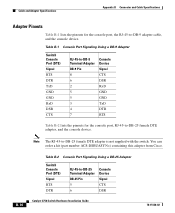
... GND RxD DSR CTS RJ-45-to-DB-9 Terminal Adapter DB-9 Pin 8 6 2 5 5 3 4 7 Console Device Signal CTS DSR RxD GND GND TxD DTR RTS Table B-2 lists the pinouts for the console port, the RJ-45-to -DB-25 Terminal Adapter DB-25 Pin 5 6 Console Device Signal CTS DSR B-10 Catalyst 3750... Switch Hardware Installation Guide 78-15136-02 You can order a kit (part number ACS-DSBUASYN=) containing this adapter from Cisco. Note The RJ-45-to -DB-25 female DTE adapter, and the console device. Table B-2 Console Port Signaling Using a DB-25 Adapter Switch Console ...
... GND RxD DSR CTS RJ-45-to-DB-9 Terminal Adapter DB-9 Pin 8 6 2 5 5 3 4 7 Console Device Signal CTS DSR RxD GND GND TxD DTR RTS Table B-2 lists the pinouts for the console port, the RJ-45-to -DB-25 Terminal Adapter DB-25 Pin 5 6 Console Device Signal CTS DSR B-10 Catalyst 3750... Switch Hardware Installation Guide 78-15136-02 You can order a kit (part number ACS-DSBUASYN=) containing this adapter from Cisco. Note The RJ-45-to -DB-25 female DTE adapter, and the console device. Table B-2 Console Port Signaling Using a DB-25 Adapter Switch Console ...
Hardware Installation Guide
Page 141
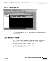
CMS Requirements These sections list the recommended platform configurations and supported operating systems, web browsers, and Java plug-ins for running CMS: • Operating System and Browser Support, page C-6 • ...
CMS Requirements These sections list the recommended platform configurations and supported operating systems, web browsers, and Java plug-ins for running CMS: • Operating System and Browser Support, page C-6 • ...

Hardware Installation Guide
Page 142
... System and Browser Support You can access CMS by Using the Cluster Management Suite Recommended Configuration for Web-Based Management Table C-1 lists the recommended platforms for running at 143 MHz with 64 MB of DRAM. The minimum UNIX workstation requirement is a Pentium processor...based management. Service Pack 3 or higher is supported. CMS Requirements Appendix C Managing the Switch by using the operating systems and browsers listed in Table C-2. Catalyst 3750 Switch Hardware Installation Guide C-6 78-15136-02 CMS checks the browser version when starting a session to ...
... System and Browser Support You can access CMS by Using the Cluster Management Suite Recommended Configuration for Web-Based Management Table C-1 lists the recommended platforms for running at 143 MHz with 64 MB of DRAM. The minimum UNIX workstation requirement is a Pentium processor...based management. Service Pack 3 or higher is supported. CMS Requirements Appendix C Managing the Switch by using the operating systems and browsers listed in Table C-2. Catalyst 3750 Switch Hardware Installation Guide C-6 78-15136-02 CMS checks the browser version when starting a session to ...
Hardware Installation Guide
Page 144
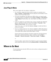
... Plug-in Control Panel), and verify these settings: In the Proxies tab, verify that Use browser settings is checked and that the plug-in is listed with the version number in the Control Panel menu. • If you have installed the Java plug-in but CMS still does not launch, make...
... Plug-in Control Panel), and verify these settings: In the Proxies tab, verify that Use browser settings is checked and that the plug-in is listed with the version number in the Control Panel menu. • If you have installed the Java plug-in but CMS still does not launch, make...

Hardware Installation Guide
Page 194
... the switch D-2 mode button 2-8 mounting, table or shelf 3-36 mounting, wall mounting 3-32 mounting brackets attaching 3-20 to 3-28 rack-mount 3-28 N noise, electrical 3-7 P packing list 3-7 PC, connecting to switch 3-9 performance problems, solving 4-3 IN-4 Catalyst 3750 Switch Hardware Installation Guide 78-15136-02
... the switch D-2 mode button 2-8 mounting, table or shelf 3-36 mounting, wall mounting 3-32 mounting brackets attaching 3-20 to 3-28 rack-mount 3-28 N noise, electrical 3-7 P packing list 3-7 PC, connecting to switch 3-9 performance problems, solving 4-3 IN-4 Catalyst 3750 Switch Hardware Installation Guide 78-15136-02