
Hardware Installation Guide
Page 2
... WebEx logo are service marks; Changing the Way We Work, Live, Play, and Learn, Cisco Capital, Cisco Capital (Design), Cisco:Financed (Stylized), Cisco Store, Flip Gift Card, and One Million Acts of Green are registered trademarks of the FCC rules. All other company. (1002R) Any Internet Protocol (IP) addresses used in accordance with FCC requirements for a Class B digital device in this manual generates and may...
... WebEx logo are service marks; Changing the Way We Work, Live, Play, and Learn, Cisco Capital, Cisco Capital (Design), Cisco:Financed (Stylized), Cisco Store, Flip Gift Card, and One Million Acts of Green are registered trademarks of the FCC rules. All other company. (1002R) Any Internet Protocol (IP) addresses used in accordance with FCC requirements for a Class B digital device in this manual generates and may...

Hardware Installation Guide
Page 21
... connect the switch to enable the auto-MDIX feature. You can use the mdix auto interface configuration command in the command-line interface (CLI) to workstations, servers, routers, and Cisco IP Phones, be sure that both devices support and full-duplex transmission if the attached device supports it senses the speed and duplex settings of the attached device and advertises its own capabilities. For configuration information for copper Ethernet connections and configures the interfaces accordingly. OL-7075-09 Catalyst 2960 Switch Hardware Installation Guide...
... connect the switch to enable the auto-MDIX feature. You can use the mdix auto interface configuration command in the command-line interface (CLI) to workstations, servers, routers, and Cisco IP Phones, be sure that both devices support and full-duplex transmission if the attached device supports it senses the speed and duplex settings of the attached device and advertises its own capabilities. For configuration information for copper Ethernet connections and configures the interfaces accordingly. OL-7075-09 Catalyst 2960 Switch Hardware Installation Guide...

Hardware Installation Guide
Page 22
... link with your IP phone or access point. The device manager, Network Assistant, and the CLI provide PoE settings for the powered device. In that came with the switch. For information about configuring and monitoring PoE ports, see the documentation that case, the PoE port becomes the backup power source for each 10/100 PoE port: - Statement 1072 • The 10/100 ports on the Catalyst 2960 switches deliver up to the switches by a crossover cable. 1-12 Catalyst 2960 Switch Hardware Installation Guide...
... link with your IP phone or access point. The device manager, Network Assistant, and the CLI provide PoE settings for the powered device. In that came with the switch. For information about configuring and monitoring PoE ports, see the documentation that case, the PoE port becomes the backup power source for each 10/100 PoE port: - Statement 1072 • The 10/100 ports on the Catalyst 2960 switches deliver up to the switches by a crossover cable. 1-12 Catalyst 2960 Switch Hardware Installation Guide...

Hardware Installation Guide
Page 23
... an SFP module connector. Chapter 1 Product Overview Front Panel Description SFP Module Slots The Catalyst 2960 switches (other switches. For more information about cabling requirements, see the software configuration guide. Each port is on the active connector. For more information about configuring speed and duplex settings for 100-Megabit connections to other than those listed) use the SFP modules for Gigabit uplink connections to establish fiber-optic connections. By default, the switch dynamically selects the interface type that first links...
... an SFP module connector. Chapter 1 Product Overview Front Panel Description SFP Module Slots The Catalyst 2960 switches (other switches. For more information about cabling requirements, see the software configuration guide. Each port is on the active connector. For more information about configuring speed and duplex settings for 100-Megabit connections to other than those listed) use the SFP modules for Gigabit uplink connections to establish fiber-optic connections. By default, the switch dynamically selects the interface type that first links...
Hardware Installation Guide
Page 32
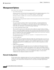
...; Cisco IOS command-line interface (CLI) The switch CLI is based on Cisco.com. • Device manager You can use the switch to create dedicated network segments that use the device manager, which you can be downloaded from a remote management station. You can use SNMP management applications such as HP OpenView or SunNet Manager. The Cisco Configuration Engine is a network management device that offers quick configuration and monitoring. You can access the CLI either by connecting your network through Gigabit Ethernet connections. 1-22 Catalyst 2960 Switch Hardware...
...; Cisco IOS command-line interface (CLI) The switch CLI is based on Cisco.com. • Device manager You can use the switch to create dedicated network segments that use the device manager, which you can be downloaded from a remote management station. You can use SNMP management applications such as HP OpenView or SunNet Manager. The Cisco Configuration Engine is a network management device that offers quick configuration and monitoring. You can access the CLI either by connecting your network through Gigabit Ethernet connections. 1-22 Catalyst 2960 Switch Hardware...
Hardware Installation Guide
Page 34
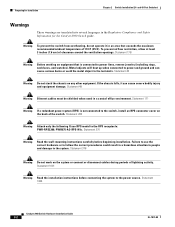
...-AC-RPS-N1=. Statement 370 Warning Read the wall-mounting instructions carefully before connecting the system to power lines, remove jewelry (including rings, necklaces, and watches). Statement 171 Warning If a redundant power system (RPS) is connected to the power source. Statement 378 Warning Do not work on the back of clearance around the ventilation openings. Statement 1004 Catalyst 2960 Switch Hardware Installation Guide 2-2 OL-7075-09
...-AC-RPS-N1=. Statement 370 Warning Read the wall-mounting instructions carefully before connecting the system to power lines, remove jewelry (including rings, necklaces, and watches). Statement 171 Warning If a redundant power system (RPS) is connected to the power source. Statement 378 Warning Do not work on the back of clearance around the ventilation openings. Statement 1004 Catalyst 2960 Switch Hardware Installation Guide 2-2 OL-7075-09

Hardware Installation Guide
Page 36
... acceptable working environments and acceptable levels of the hazard. Catalyst 2960 switch SFP ports can result in a system malfunction. Avoid using uninsulated exposed metal contacts, conductors, or terminals. Statement 1072 Warning No user-serviceable parts inside the chassis, which lists the cable specifications for 1000BASE-X and 100BASE-X SFP modules for the Catalyst 2960-8TC-L, 2960-8TC-S, 2960G-8TC-L, and 2960PD-8TT-L switches. Statement 1074 Guidelines for Installation Chapter 2 Switch Installation...
... acceptable working environments and acceptable levels of the hazard. Catalyst 2960 switch SFP ports can result in a system malfunction. Avoid using uninsulated exposed metal contacts, conductors, or terminals. Statement 1072 Warning No user-serviceable parts inside the chassis, which lists the cable specifications for 1000BASE-X and 100BASE-X SFP modules for the Catalyst 2960-8TC-L, 2960-8TC-S, 2960G-8TC-L, and 2960PD-8TT-L switches. Statement 1074 Guidelines for Installation Chapter 2 Switch Installation...

Hardware Installation Guide
Page 38
... some time and then reflects the switch operating status. If a switch fails POST, the System LED turns amber. Install the switch in a rack, on a wall, on a table, or on a shelf as described in this section might not show your specific switch; For information applicable to those switches, see Chapter 3, "Switch Installation (8-Port Switches)." or Shelf-Mounting, page 2-14 Rack-Mounting This section applies to those switches, see Chapter 3, "Switch Installation (8-Port Switches)." and 48-port switches. Statement 1006 Catalyst 2960 Switch Hardware Installation Guide...
... some time and then reflects the switch operating status. If a switch fails POST, the System LED turns amber. Install the switch in a rack, on a wall, on a table, or on a shelf as described in this section might not show your specific switch; For information applicable to those switches, see Chapter 3, "Switch Installation (8-Port Switches)." or Shelf-Mounting, page 2-14 Rack-Mounting This section applies to those switches, see Chapter 3, "Switch Installation (8-Port Switches)." and 48-port switches. Statement 1006 Catalyst 2960 Switch Hardware Installation Guide...
Hardware Installation Guide
Page 45
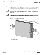
... the best support of the switch. and 48-Port Switches) Installing the Switch Mounting the Switch on a Wall 11X 12X 11X 1X 12X 11X 1X 12X 1X 1X 11X 1X 12X MODE STASCPKEDEUDPSLTXAMTASRTPRSSYST 1 1 1 User-supplied screws 204621 OL-7075-09 Catalyst 2960 Switch Hardware Installation Guide 2-13 Warning To comply with safety regulations, mount the switches on the back of the switch and cables, make sure the switch is not connected to...
... the best support of the switch. and 48-Port Switches) Installing the Switch Mounting the Switch on a Wall 11X 12X 11X 1X 12X 11X 1X 12X 1X 1X 11X 1X 12X MODE STASCPKEDEUDPSLTXAMTASRTPRSSYST 1 1 1 User-supplied screws 204621 OL-7075-09 Catalyst 2960 Switch Hardware Installation Guide 2-13 Warning To comply with safety regulations, mount the switches on the back of the switch and cables, make sure the switch is not connected to...

Hardware Installation Guide
Page 47
... a cable problem or a problem with the adapter installed in SFP module slots on page B-4 for solutions to 30 seconds, and then the port LED turns green. See the "SFP Module Cable Specifications" section on the front of SFP modules that the Catalyst 2960 switch supports. The auto-MDIX feature is amber while Spanning Tree Protocol (STP) discovers the topology and searches for this feature, see the switch software configuration guide or the switch command reference. The port LED is enabled by default. These field-replaceable modules...
... a cable problem or a problem with the adapter installed in SFP module slots on page B-4 for solutions to 30 seconds, and then the port LED turns green. See the "SFP Module Cable Specifications" section on the front of SFP modules that the Catalyst 2960 switch supports. The auto-MDIX feature is amber while Spanning Tree Protocol (STP) discovers the topology and searches for this feature, see the switch software configuration guide or the switch command reference. The port LED is enabled by default. These field-replaceable modules...
Hardware Installation Guide
Page 48
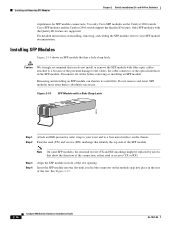
Installing and Removing SFP Modules Chapter 2 Switch Installation (24- Removing and installing an SFP module can shorten its useful life. Do not remove and insert SFP modules more often than is absolutely necessary. and 48-Port Switches) stipulations for SFP module connections. For detailed instructions on installing, removing, and cabling the SFP module, refer to your wrist and to a bare metal surface on the chassis. Figure 2-14 SFP Module with a Bale-Clasp Latch 86575 Step 1 Attach an ESD-preventive wrist...
Installing and Removing SFP Modules Chapter 2 Switch Installation (24- Removing and installing an SFP module can shorten its useful life. Do not remove and insert SFP modules more often than is absolutely necessary. and 48-Port Switches) stipulations for SFP module connections. For detailed instructions on installing, removing, and cabling the SFP module, refer to your wrist and to a bare metal surface on the chassis. Figure 2-14 SFP Module with a Bale-Clasp Latch 86575 Step 1 Attach an ESD-preventive wrist...

Hardware Installation Guide
Page 57
... handled according to all national laws and regulations. Statement 1046 Warning No user-serviceable parts inside. Statement 1074 Installation Guidelines This section is installed in a closed environment or in a multirack assembly, the temperature around it might be grounded. and 48-Port Switches)." OL-7075-09 Catalyst 2960 Switch Hardware Installation Guide 3-3 Contact the appropriate electrical inspection authority or an electrician if you...
... handled according to all national laws and regulations. Statement 1046 Warning No user-serviceable parts inside. Statement 1074 Installation Guidelines This section is installed in a closed environment or in a multirack assembly, the temperature around it might be grounded. and 48-Port Switches)." OL-7075-09 Catalyst 2960 Switch Hardware Installation Guide 3-3 Contact the appropriate electrical inspection authority or an electrician if you...
Hardware Installation Guide
Page 73
... on Cisco.com, or the documentation that came with your SNMP application for details. They show failures in the power-on page 4-4 OL-7075-09 Catalyst 2960 Switch Hardware Installation Guide 4-1 See the software configuration guide, the switch command reference guide on page 1-14. You can also get statistics from the browser interface, from the command-line interface (CLI), or from an SNMP workstation. You can also get statistics from the CLI or from a Simple Network Management Protocol (SNMP...
... on Cisco.com, or the documentation that came with your SNMP application for details. They show failures in the power-on page 4-4 OL-7075-09 Catalyst 2960 Switch Hardware Installation Guide 4-1 See the software configuration guide, the switch command reference guide on page 1-14. You can also get statistics from the browser interface, from the command-line interface (CLI), or from an SNMP workstation. You can also get statistics from the CLI or from a Simple Network Management Protocol (SNMP...

Hardware Installation Guide
Page 75
... the module meets the requirements for the switch. This encoding provides a way for Cisco to show interfaces privileged EXEC command to function at a marginal level. Look for 10 Mb/s unshielded twisted pair (UTP) connections. Re-enable the port if necessary. • Make sure that all fiber-optic connections. Chapter 4 Troubleshooting Diagnosing Problems Ethernet and Fiber Cables Make sure that you have properly cleaned and securely connected all...
... the module meets the requirements for the switch. This encoding provides a way for Cisco to show interfaces privileged EXEC command to function at a marginal level. Look for 10 Mb/s unshielded twisted pair (UTP) connections. Re-enable the port if necessary. • Make sure that all fiber-optic connections. Chapter 4 Troubleshooting Diagnosing Problems Ethernet and Fiber Cables Make sure that you have properly cleaned and securely connected all...
Hardware Installation Guide
Page 76
... 4 Troubleshooting Port and Interface Settings An obvious but the switch does not receive the traffic that is sent from the directly connected switch, and then work your way back port by port, interface by interface, trunk by trunk, until you find unidirectional link problems. UDLD supports a normal mode of the connection. A unidirectional link can cause serious performance issues that the switch sends is a disabled port. Verify that each switch can identify the end device MAC address in the software configuration guide. Ping...
... 4 Troubleshooting Port and Interface Settings An obvious but the switch does not receive the traffic that is sent from the directly connected switch, and then work your way back port by port, interface by interface, trunk by trunk, until you find unidirectional link problems. UDLD supports a normal mode of the connection. A unidirectional link can cause serious performance issues that the switch sends is a disabled port. Verify that each switch can identify the end device MAC address in the software configuration guide. Ping...
Hardware Installation Guide
Page 77
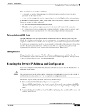
... switch to also be causing the problem. The LEDs stop blinking after about 2 seconds. Chapter 4 Troubleshooting Clearing the Switch IP Address and Configuration These circumstances can result in a mismatch: • A manually set speed or duplex parameter is different from the manufacturer. for devices such as laptop computers or other devices to the factory default settings: 1. If the switch is common for cabling guidelines. It is not configured, the LEDs above the mode button turn green...
... switch to also be causing the problem. The LEDs stop blinking after about 2 seconds. Chapter 4 Troubleshooting Clearing the Switch IP Address and Configuration These circumstances can result in a mismatch: • A manually set speed or duplex parameter is different from the manufacturer. for devices such as laptop computers or other devices to the factory default settings: 1. If the switch is common for cabling guidelines. It is not configured, the LEDs above the mode button turn green...
Hardware Installation Guide
Page 95
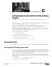
...-09 Catalyst 2960 Switch Hardware Installation Guide C-1 Starting the Terminal Emulation Software, page C-3 4. Enter the setup user EXEC command. Connecting to the small form-factor pluggable (SFP) modules, see Chapter 1, "Product Overview." Connecting to do an installation: 1. These steps describe how to a Power Source, page C-4 5. Entering the Initial Configuration Information, page C-4 Accessing the CLI For an unconfigured switch, you connect the switch to the Ethernet port of your switch, connecting to the switch ports, or connecting to the Console Port, page...
...-09 Catalyst 2960 Switch Hardware Installation Guide C-1 Starting the Terminal Emulation Software, page C-3 4. Enter the setup user EXEC command. Connecting to the small form-factor pluggable (SFP) modules, see Chapter 1, "Product Overview." Connecting to do an installation: 1. These steps describe how to a Power Source, page C-4 5. Entering the Initial Configuration Information, page C-4 Accessing the CLI For an unconfigured switch, you connect the switch to the Ethernet port of your switch, connecting to the switch ports, or connecting to the Console Port, page...

Hardware Installation Guide
Page 98
... the supplied AC power cord to the power connector on your switch fails POST. Call Cisco technical support representative if your switch, the PC or terminal displays the bootloader sequence. Catalyst 2960 Switch Hardware Installation Guide C-4 OL-7075-09 Connect the other LEDs turn green. Note If you need to press Enter to display the setup program prompt. The System LED blinks green, and the other configuration information necessary for some time and...
... the supplied AC power cord to the power connector on your switch fails POST. Call Cisco technical support representative if your switch, the PC or terminal displays the bootloader sequence. Catalyst 2960 Switch Hardware Installation Guide C-4 OL-7075-09 Connect the other LEDs turn green. Note If you need to press Enter to display the setup program prompt. The System LED blinks green, and the other configuration information necessary for some time and...
Hardware Installation Guide
Page 104
...B-3 SFP module ports B-3 console port connecting to C-3 described 1-21 specifications B-4 to B-8 crossover cable B-7 crossover cable, connecting to 1000BASE-T SFP module ports 2-19 crossover cable pinout, four twisted-pair, 1000BASE-T ports B-7 D DC power RPS 1-3 IN-2 Catalyst 2960 Switch Hardware Installation Guide descriptions of switch models 1-1 desk-mounting 2-14, 3-6 device manager described 1-22 to 1-17 SFP module ports 1-13 OL-7075-09 and 48-port switches 2-2 8-port switches 3-2 Ethernet ports warning 3-3 examples, network configuration 1-1 Express Setup, accessing CLI by using...
...B-3 SFP module ports B-3 console port connecting to C-3 described 1-21 specifications B-4 to B-8 crossover cable B-7 crossover cable, connecting to 1000BASE-T SFP module ports 2-19 crossover cable pinout, four twisted-pair, 1000BASE-T ports B-7 D DC power RPS 1-3 IN-2 Catalyst 2960 Switch Hardware Installation Guide descriptions of switch models 1-1 desk-mounting 2-14, 3-6 device manager described 1-22 to 1-17 SFP module ports 1-13 OL-7075-09 and 48-port switches 2-2 8-port switches 3-2 Ethernet ports warning 3-3 examples, network configuration 1-1 Express Setup, accessing CLI by using...

Hardware Installation Guide
Page 107
... twisted-pair 10/100 ports B-6 SunNet Manager 1-22 switch descriptions 1-1 switch powering on 2-5, 3-5 system LED 1-15 T technical specifications A-1 telco racks 2-7, 3-15 Telnet, and accessing the CLI 1-22 temperature, operating A-1 terminal emulation software C-3 trained and qualified personnel warning 2-3 troubleshooting 4-1 to 4-6 OL-7075-09 Index bad or damaged cable 4-2 connection problems 4-2 diagnosing problems 4-1 Ethernet and fiber-optic cables 4-3 link status 4-3 ping end device 4-4 port and interface settings 4-4 POST 4-1 spanning tree loops 4-4 speed, duplex, and autonegotiation...
... twisted-pair 10/100 ports B-6 SunNet Manager 1-22 switch descriptions 1-1 switch powering on 2-5, 3-5 system LED 1-15 T technical specifications A-1 telco racks 2-7, 3-15 Telnet, and accessing the CLI 1-22 temperature, operating A-1 terminal emulation software C-3 trained and qualified personnel warning 2-3 troubleshooting 4-1 to 4-6 OL-7075-09 Index bad or damaged cable 4-2 connection problems 4-2 diagnosing problems 4-1 Ethernet and fiber-optic cables 4-3 link status 4-3 ping end device 4-4 port and interface settings 4-4 POST 4-1 spanning tree loops 4-4 speed, duplex, and autonegotiation...


