
Hardware Installation Guide
Page 3
... and Modes 1-16 Dual-Purpose Port LEDs 1-18 Cable Guard for the Catalyst 2960 8-Port Switches 1-19 Rear Panel Description 1-19 Internal Power Supply 1-20 Cisco RPS 1-20 Cisco RPS 2300 1-20 Cisco RPS 675 1-21 Console Port 1-21 Security Slots 1-21 Management Options 1-22 Network Configurations 1-22 Catalyst 2960 Switch Hardware Installation Guide iii...
... and Modes 1-16 Dual-Purpose Port LEDs 1-18 Cable Guard for the Catalyst 2960 8-Port Switches 1-19 Rear Panel Description 1-19 Internal Power Supply 1-20 Cisco RPS 1-20 Cisco RPS 2300 1-20 Cisco RPS 675 1-21 Console Port 1-21 Security Slots 1-21 Management Options 1-22 Network Configurations 1-22 Catalyst 2960 Switch Hardware Installation Guide iii...

Hardware Installation Guide
Page 13
...information about switch support for an optional Cisco RPS 2300 or Cisco RPS 675 redundant power system that operates on specific switches, see the Cisco Gigabit Ethernet Transceiver Modules Compatibility Matrix at this Cisco.com URL: http://www.cisco.com/en/US/docs/interfaces_modules/transceiver_modules/compatibility/...switches. Chapter 1 Product Overview Features These are supported on AC input and supplies backup DC power to the switch. See the compatibility matrix documents for the RPS systems on Cisco.com for more information about which SFP modules are the SFP modules supported ...
...information about switch support for an optional Cisco RPS 2300 or Cisco RPS 675 redundant power system that operates on specific switches, see the Cisco Gigabit Ethernet Transceiver Modules Compatibility Matrix at this Cisco.com URL: http://www.cisco.com/en/US/docs/interfaces_modules/transceiver_modules/compatibility/...switches. Chapter 1 Product Overview Features These are supported on AC input and supplies backup DC power to the switch. See the compatibility matrix documents for the RPS systems on Cisco.com for more information about which SFP modules are the SFP modules supported ...

Hardware Installation Guide
Page 26
...RPS Status RPS is the default mode. DUPLX SPEED1 PoE2 Port duplex mode Port speed PoE port power The port duplex mode: full duplex or half duplex. Contact Cisco Systems. The internal power supply in a switch has failed, and the RPS is connected and ready to this device). The .../Active button on the Catalyst 2960 PoE switches. 1-16 Catalyst 2960 Switch Hardware Installation Guide OL-7075-09 The PoE LED is providing power to another device (redundancy has been allocated to a neighboring device). Front Panel Description Chapter 1 Product Overview RPS LED The RPS LED ...
...RPS Status RPS is the default mode. DUPLX SPEED1 PoE2 Port duplex mode Port speed PoE port power The port duplex mode: full duplex or half duplex. Contact Cisco Systems. The internal power supply in a switch has failed, and the RPS is connected and ready to this device). The .../Active button on the Catalyst 2960 PoE switches. 1-16 Catalyst 2960 Switch Hardware Installation Guide OL-7075-09 The PoE LED is providing power to another device (redundancy has been allocated to a neighboring device). Front Panel Description Chapter 1 Product Overview RPS LED The RPS LED ...
Hardware Installation Guide
Page 29
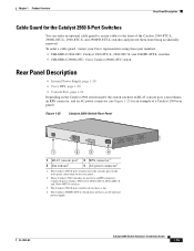
... do not have an AC internal power supply. To order a cable guard, contact your Cisco representative using these part numbers: • CBLGRD-C2960-8TC: Catalyst 2960-8TC-L, 2960-8TC-S, and 2960PD-8TT-L switches • CBLGRD-C2960G-8TC: Cisco Catalyst 2960G-8TC switch Rear Panel Description • Internal Power Supply, page 1-20 • Cisco RPS, page 1-20 • Console...
... do not have an AC internal power supply. To order a cable guard, contact your Cisco representative using these part numbers: • CBLGRD-C2960-8TC: Catalyst 2960-8TC-L, 2960-8TC-S, and 2960PD-8TT-L switches • CBLGRD-C2960G-8TC: Cisco Catalyst 2960G-8TC switch Rear Panel Description • Internal Power Supply, page 1-20 • Cisco RPS, page 1-20 • Console...
Hardware Installation Guide
Page 30
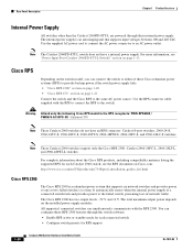
...connect the RPS to the same AC power source. Cisco RPS Depending on the switch model, you can configure these Cisco redundant power systems (RPS) to provide backup power if the switch power supply fails: • "Cisco RPS 2300" section on page 1-20 • "Cisco RPS 675" section on page 1-21... the switch to either of these RPS 2300 features through their internal power supply. The internal power supply is a redundant power system that supports input voltages between 100 and 240 VAC. Warning Attach only the following Cisco RPS model to one or two failed switches at a time. For...
...connect the RPS to the same AC power source. Cisco RPS Depending on the switch model, you can configure these Cisco redundant power systems (RPS) to provide backup power if the switch power supply fails: • "Cisco RPS 2300" section on page 1-20 • "Cisco RPS 675" section on page 1-21... the switch to either of these RPS 2300 features through their internal power supply. The internal power supply is a redundant power system that supports input voltages between 100 and 240 VAC. Warning Attach only the following Cisco RPS model to one or two failed switches at a time. For...

Hardware Installation Guide
Page 31
... switch to a PC by the RPS • Obtain status reports for the RPS power-supply module • Read and monitor backup, failure, and exception history Cisco RPS 675 The Cisco 675 RPS is a redundant power system that supports six network devices and provides power to -DB-9 female cable. You can install an optional cable lock, such...
... switch to a PC by the RPS • Obtain status reports for the RPS power-supply module • Read and monitor backup, failure, and exception history Cisco RPS 675 The Cisco 675 RPS is a redundant power system that supports six network devices and provides power to -DB-9 female cable. You can install an optional cable lock, such...
Hardware Installation Guide
Page 35
... is intended for Installation Warning To prevent bodily injury when mounting or servicing this equipment. Statement 1024 Warning This unit might have more than one power supply connection. and 48-Port Switches) Preparing for installation in the rack. Statement 1030 Warning Ultimate disposal of this unit in the absence of the rack...
... is intended for Installation Warning To prevent bodily injury when mounting or servicing this equipment. Statement 1024 Warning This unit might have more than one power supply connection. and 48-Port Switches) Preparing for installation in the rack. Statement 1030 Warning Ultimate disposal of this unit in the absence of the rack...

Hardware Installation Guide
Page 37
.... If any item is away from other end of single-mode fiber cable, you might need to supply a number-2 Phillips screwdriver to active mode during normal operation. To power on the switch, connect one end of the link. • The operating environment must be greater than 15.43 miles...does not exceed 113°F (45°C). OL-7075-09 Catalyst 2960 Switch Hardware Installation Guide 2-5 Verifying Switch Operation Before you should power on Cisco.com describes the box contents. Set the RPS to rack-mount the switch. When the fiber-optic cable span is installed in the ...
.... If any item is away from other end of single-mode fiber cable, you might need to supply a number-2 Phillips screwdriver to active mode during normal operation. To power on the switch, connect one end of the link. • The operating environment must be greater than 15.43 miles...does not exceed 113°F (45°C). OL-7075-09 Catalyst 2960 Switch Hardware Installation Guide 2-5 Verifying Switch Operation Before you should power on Cisco.com describes the box contents. Set the RPS to rack-mount the switch. When the fiber-optic cable span is installed in the ...
Hardware Installation Guide
Page 42
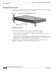
... "Connecting to SFP Modules" section on page 2-18, and the "Connecting to a Dual-Purpose Port" section on page 2-5. • Connect to complete the installation: • Power on the switch. and 48-Port Switches) Mounting the Switch in a Rack After the brackets are attached to the switch, use the four... supplied number-12 Phillips machine screws to securely attach the brackets to the rack, as shown in the rack, do these tasks to a 10/100 or ...
... "Connecting to SFP Modules" section on page 2-18, and the "Connecting to a Dual-Purpose Port" section on page 2-5. • Connect to complete the installation: • Power on the switch. and 48-Port Switches) Mounting the Switch in a Rack After the brackets are attached to the switch, use the four... supplied number-12 Phillips machine screws to securely attach the brackets to the rack, as shown in the rack, do these tasks to a 10/100 or ...
Hardware Installation Guide
Page 45
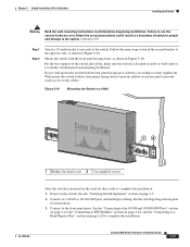
... the back of the switch and cables, make sure the switch is not connected to a firmly attached plywood mounting backboard. Statement 266 Warning If a redundant power system (RPS) is attached securely to wall studs or to the switch, install an RPS connector cover on a Wall 11X 12X 11X 1X 12X 11X... 1X 12X 1X 1X 11X 1X 12X MODE STASCPKEDEUDPSLTXAMTASRTPRSSYST 1 1 1 User-supplied screws 204621 OL-7075-09 Catalyst 2960 Switch Hardware Installation Guide 2-13 Chapter 2 Switch Installation (24-
... the back of the switch and cables, make sure the switch is not connected to a firmly attached plywood mounting backboard. Statement 266 Warning If a redundant power system (RPS) is attached securely to wall studs or to the switch, install an RPS connector cover on a Wall 11X 12X 11X 1X 12X 11X... 1X 12X 1X 1X 11X 1X 12X MODE STASCPKEDEUDPSLTXAMTASRTPRSSYST 1 1 1 User-supplied screws 204621 OL-7075-09 Catalyst 2960 Switch Hardware Installation Guide 2-13 Chapter 2 Switch Installation (24-

Hardware Installation Guide
Page 55
... Preparing for Installation This section covers these topics: • Warnings, page 3-1 • Installation Guidelines, page 3-3 • Equipment That You Supply, page 3-4 • Box Contents, page 3-5 • Tools and Equipment, page 3-5 Warnings These warnings are translated into several languages in ...H A P T E R Switch Installation (8-Port Switches) This chapter describes how to start your switch and how to interpret the power-on self-test (POST) that exceeds the maximum recommended ambient temperature of clearance around the ventilation openings. It also describes how to ...
... Preparing for Installation This section covers these topics: • Warnings, page 3-1 • Installation Guidelines, page 3-3 • Equipment That You Supply, page 3-4 • Box Contents, page 3-5 • Tools and Equipment, page 3-5 Warnings These warnings are translated into several languages in ...H A P T E R Switch Installation (8-Port Switches) This chapter describes how to start your switch and how to interpret the power-on self-test (POST) that exceeds the maximum recommended ambient temperature of clearance around the ventilation openings. It also describes how to ...

Hardware Installation Guide
Page 58
... avoid overloading the receiver. To order a cable guard, contact your Cisco representative and use these conditions - Cable locks are separated on all... 2960 Switch Hardware Installation Guide 3-4 OL-7075-09 Equipment That You Supply This section is sufficient for the Catalyst 2960 switch. You can use... 2960-8TC-S, and 2960PD-8TT-L switches cable guard part number: CBLGRD-C2960-8TC= • Catalyst 2960G-8TC-L switch cable guard part number: CBLGRD...8226; Clearance to the Catalyst 2960 8-port switches. The AC power cord can easily read the front-panel indicators. - When the...
... avoid overloading the receiver. To order a cable guard, contact your Cisco representative and use these conditions - Cable locks are separated on all... 2960 Switch Hardware Installation Guide 3-4 OL-7075-09 Equipment That You Supply This section is sufficient for the Catalyst 2960 switch. You can use... 2960-8TC-S, and 2960PD-8TT-L switches cable guard part number: CBLGRD-C2960-8TC= • Catalyst 2960G-8TC-L switch cable guard part number: CBLGRD...8226; Clearance to the Catalyst 2960 8-port switches. The AC power cord can easily read the front-panel indicators. - When the...

Hardware Installation Guide
Page 59
...and Speed LEDs turn off and then reflect the switch operating status. POST failures are usually fatal. After a successful POST, disconnect the power cord from Cisco. For information applicable to -DB-25 female DTE adapter. or Shelf-Mounting (with the switch. The kit part number is specific to ...rack-mount the switch. Box Contents The switch getting started guide on page 3-5. As the switch powers on a desk, a shelf, or a wall, you need to supply ...
...and Speed LEDs turn off and then reflect the switch operating status. POST failures are usually fatal. After a successful POST, disconnect the power cord from Cisco. For information applicable to -DB-25 female DTE adapter. or Shelf-Mounting (with the switch. The kit part number is specific to ...rack-mount the switch. Box Contents The switch getting started guide on page 3-5. As the switch powers on a desk, a shelf, or a wall, you need to supply ...
Hardware Installation Guide
Page 71
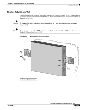
... with the front panel facing down to prevent airflow restriction and to provide easier access to follow the correct procedures could result in Figure 3-10. Power on page 3-5. 2. Connect to complete the installation. See the "Connecting to the 10/100 and 10/100/1000 Ports" section on page 2-14, ... to SFP Modules" section on page 2-18, and the "Connecting to a Dual-Purpose Port" section on a Wall 12 204634 1 Phillips flat-head screw 2 User-supplied screws After the switch is attached securely to wall studs or to the opposite side, as shown in Figure 3-10. Failure to use the correct...
... with the front panel facing down to prevent airflow restriction and to provide easier access to follow the correct procedures could result in Figure 3-10. Power on page 3-5. 2. Connect to complete the installation. See the "Connecting to the 10/100 and 10/100/1000 Ports" section on page 2-14, ... to SFP Modules" section on page 2-18, and the "Connecting to a Dual-Purpose Port" section on a Wall 12 204634 1 Phillips flat-head screw 2 User-supplied screws After the switch is attached securely to wall studs or to the opposite side, as shown in Figure 3-10. Failure to use the correct...
Hardware Installation Guide
Page 97
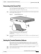
...Console Port Connecting to the Console Port You can see the output display from the power-on self-test (POST). Follow these steps to connect the PC or terminal to the switch: Step 1 Using the supplied RJ-45-to-DB-9 adapter cable, insert the RJ-45 connector into the ... serial port, or attach an appropriate adapter to -DB-9 adapter cable. Step 1 Start the terminal-emulation program and open a session if you can use the supplied RJ-45-to the terminal. Step 2 Start a terminal-emulation session. Figure C-1 Connecting a Switch to a PC 1 CONSOLE 137088 3 2 1 Catalyst 2960 switch 3 RJ-45...
...Console Port Connecting to the Console Port You can see the output display from the power-on self-test (POST). Follow these steps to connect the PC or terminal to the switch: Step 1 Using the supplied RJ-45-to-DB-9 adapter cable, insert the RJ-45 connector into the ... serial port, or attach an appropriate adapter to -DB-9 adapter cable. Step 1 Start the terminal-emulation program and open a session if you can use the supplied RJ-45-to the terminal. Step 2 Start a terminal-emulation session. Figure C-1 Connecting a Switch to a PC 1 CONSOLE 137088 3 2 1 Catalyst 2960 switch 3 RJ-45...

Hardware Installation Guide
Page 98
... supplied AC power cord to the power connector on your switch fails POST. The System LED blinks green, and the other end of the power cable to a grounded AC outlet. Note If you are usually fatal. If a switch fails POST, the System LED turns amber. Call Cisco... Hardware Installation Guide C-4 OL-7075-09 POST failures are connecting the switch to a Cisco redundant power system (RPS), refer to the documentation that the switch functions properly. Connecting to a Power Source Appendix C Configuring the Switch with the CLI-Based Setup Program Step 3 Configure ...
... supplied AC power cord to the power connector on your switch fails POST. The System LED blinks green, and the other end of the power cable to a grounded AC outlet. Note If you are usually fatal. If a switch fails POST, the System LED turns amber. Call Cisco... Hardware Installation Guide C-4 OL-7075-09 POST failures are connecting the switch to a Cisco redundant power system (RPS), refer to the documentation that the switch functions properly. Connecting to a Power Source Appendix C Configuring the Switch with the CLI-Based Setup Program Step 3 Configure ...

Hardware Installation Guide
Page 105
...Index G ground connection warning 2-4, 3-3 grounded equipment warning 2-3, 3-3 H HP OpenView 1-22 humidity, relative A-1 I installation assigning the IP address C-4 connecting to 2-17 internal power supply 1-20 J jewelry removal warning 2-2, 3-2 L LEDs OL-7075-09 color meanings 1-17 dual-purpose port 1-18 duplex 1-16 front panel 1-15 interpreting 1-17 PoE 1-16... 3-8 using a magnet 3-14 site requirements 2-4, 3-3 starting the terminal emulation software C-3 See also procedures installation instructions warning 2-2, 3-2 installing SFP modules 2-16 to a power source C-4 mounting in a rack (24-
...Index G ground connection warning 2-4, 3-3 grounded equipment warning 2-3, 3-3 H HP OpenView 1-22 humidity, relative A-1 I installation assigning the IP address C-4 connecting to 2-17 internal power supply 1-20 J jewelry removal warning 2-2, 3-2 L LEDs OL-7075-09 color meanings 1-17 dual-purpose port 1-18 duplex 1-16 front panel 1-15 interpreting 1-17 PoE 1-16... 3-8 using a magnet 3-14 site requirements 2-4, 3-3 starting the terminal emulation software C-3 See also procedures installation instructions warning 2-2, 3-2 installing SFP modules 2-16 to a power source C-4 mounting in a rack (24-
Hardware Installation Guide
Page 106
...results 2-6, 3-5, 4-1, C-4 running at power on 2-6, 3-5, 4-2 power connecting to 2-5, 3-5 connectors 1-19, 1-20 power on 2-5, 3-5 IN-4 Catalyst 2960 Switch Hardware Installation Guide power-on self test See POST Power over Ethernet See PoE Power over Ethernet See PoE power supply AC power outlet 1-20 for the Catalyst 2960PD-8TT... 3-15 read the wall-mounting instructions warning 2-2, 3-11, 3-17 rear panel clearance 2-5, 3-4 description 1-19 to 1-21 redundant power supply See RPS removing SFP modules 2-17 to 2-18 restricted access area warning 2-3 RJ-45 connector, console port B-4 RJ-45 console...
...results 2-6, 3-5, 4-1, C-4 running at power on 2-6, 3-5, 4-2 power connecting to 2-5, 3-5 connectors 1-19, 1-20 power on 2-5, 3-5 IN-4 Catalyst 2960 Switch Hardware Installation Guide power-on self test See POST Power over Ethernet See PoE Power over Ethernet See PoE power supply AC power outlet 1-20 for the Catalyst 2960PD-8TT... 3-15 read the wall-mounting instructions warning 2-2, 3-11, 3-17 rear panel clearance 2-5, 3-4 description 1-19 to 1-21 redundant power supply See RPS removing SFP modules 2-17 to 2-18 restricted access area warning 2-3 RJ-45 connector, console port B-4 RJ-45 console...

Hardware Installation Guide
Page 107
... tree loops 4-4 W wall-mounting 2-11, 3-16 warnings attaching the Cisco RPS 2-2, 2-6 circuit protection 2-3 class 1 laser product 2-3, 3-2 disconnecting device 2-3 Ethernet cables 2-2, 3-2 Ethernet ports 3-3 ground connection 2-4, 3-3 grounded equipment 2-3, 3-3 installation 2-2, 3-1 installation instructions 2-2, 3-2 jewelry removal 2-2, 3-2 lightning activity 2-2, 3-2 local and national electrical codes compliance 2-4, 3-3 more than one power supply 3-3 no user-serviceable parts 2-4 overheating prevention 2-2, 3-1 plug-socket combination...
... tree loops 4-4 W wall-mounting 2-11, 3-16 warnings attaching the Cisco RPS 2-2, 2-6 circuit protection 2-3 class 1 laser product 2-3, 3-2 disconnecting device 2-3 Ethernet cables 2-2, 3-2 Ethernet ports 3-3 ground connection 2-4, 3-3 grounded equipment 2-3, 3-3 installation 2-2, 3-1 installation instructions 2-2, 3-2 jewelry removal 2-2, 3-2 lightning activity 2-2, 3-2 local and national electrical codes compliance 2-4, 3-3 more than one power supply 3-3 no user-serviceable parts 2-4 overheating prevention 2-2, 3-1 plug-socket combination...


