

Hardware Installation Guide
Page 19
...an EHWIC in a 1905 or 1921. 5. OL-19084-02 Cisco 1900 Series Hardware Installation 1-3 Figure 1-2 shows the back panel of the Cisco 1905 and Cisco 1921 Router (1921 shown) 1 EHWIC 1 FLASH 18 EHWIC 0 234 5 6 9 10 11 12 13 14 AUX S GE 0/1 L Cisco 1921 EN 17 16 EN CONSOLE S GE 0/0 L 78 ...3 RJ-45 serial console port 4 AUX port 5 GE 0/1 7 S (Speed) 9 USB port-USB 2.0 Type-A port 11 PoE6 13 On/Off switch 6 GE 0/0 8 L (Link) 10 KensingtonTM security slot 12 Ground connector 14 Input power connection 15 Baud reset 17 EN (Enable USB console) 16 USB serial port-USB 5-pin mini USB...
...an EHWIC in a 1905 or 1921. 5. OL-19084-02 Cisco 1900 Series Hardware Installation 1-3 Figure 1-2 shows the back panel of the Cisco 1905 and Cisco 1921 Router (1921 shown) 1 EHWIC 1 FLASH 18 EHWIC 0 234 5 6 9 10 11 12 13 14 AUX S GE 0/1 L Cisco 1921 EN 17 16 EN CONSOLE S GE 0/0 L 78 ...3 RJ-45 serial console port 4 AUX port 5 GE 0/1 7 S (Speed) 9 USB port-USB 2.0 Type-A port 11 PoE6 13 On/Off switch 6 GE 0/0 8 L (Link) 10 KensingtonTM security slot 12 Ground connector 14 Input power connection 15 Baud reset 17 EN (Enable USB console) 16 USB serial port-USB 5-pin mini USB...

Hardware Installation Guide
Page 21
... 17 18 19 20 21 22 EHWIC 1 DO NOT REMOVE DURING NETWORKING OPERATION CF 1 Cisco 1900 Series EHWIC 0 DO NOT REMOVE DURING CF 0 ISM/WLAN EN NETWORKING OPERATION AUX S L G E 0 / 0 EN CONSOLE GE 0/1 S L 1 USB 0 273452 16 15 14 13 12 11 10 9 8 7 6 5 4 3 2 1 USB ports-two USB 2.0 Type-A ports 1 (USB 0=Bottom) L ...wide2 EN (Enable USB console) 8 10 ISM3 or WLAN 11 CF 0 12 CompactFlash 0 13 HWIC slot 1 (EHWIC, HWIC, or WIC)-double wide4 15 CompactFlash 1 14 CF 1 16 KensingtonTM security slot 17 On/Off switch 18 Input power connection 19 AUX port 20 S (Speed) 21 GE ...
... 17 18 19 20 21 22 EHWIC 1 DO NOT REMOVE DURING NETWORKING OPERATION CF 1 Cisco 1900 Series EHWIC 0 DO NOT REMOVE DURING CF 0 ISM/WLAN EN NETWORKING OPERATION AUX S L G E 0 / 0 EN CONSOLE GE 0/1 S L 1 USB 0 273452 16 15 14 13 12 11 10 9 8 7 6 5 4 3 2 1 USB ports-two USB 2.0 Type-A ports 1 (USB 0=Bottom) L ...wide2 EN (Enable USB console) 8 10 ISM3 or WLAN 11 CF 0 12 CompactFlash 0 13 HWIC slot 1 (EHWIC, HWIC, or WIC)-double wide4 15 CompactFlash 1 14 CF 1 16 KensingtonTM security slot 17 On/Off switch 18 Input power connection 19 AUX port 20 S (Speed) 21 GE ...

Hardware Installation Guide
Page 24
... Internal Service Module (ISM). Caution Power off the PoE before installing an EHWIC in Cisco 1900 Series ISRs. • The ISM connector inside . In addition to optional integrated switch modules. You will be used at the same time. The chassis cover should never ...to install the driver. Removable, Interchangeable, and Optional Modules Some modules can not both be used . Table 1-2 summarizes the optional modules: Cisco 1900 Series Hardware Installation 1-8 OL-19084-02 They can be installed. One console port (RJ-45 connector). Two USB 2.0 Type-A compliant ...
... Internal Service Module (ISM). Caution Power off the PoE before installing an EHWIC in Cisco 1900 Series ISRs. • The ISM connector inside . In addition to optional integrated switch modules. You will be used at the same time. The chassis cover should never ...to install the driver. Removable, Interchangeable, and Optional Modules Some modules can not both be used . Table 1-2 summarizes the optional modules: Cisco 1900 Series Hardware Installation 1-8 OL-19084-02 They can be installed. One console port (RJ-45 connector). Two USB 2.0 Type-A compliant ...

Hardware Installation Guide
Page 36
...missing safety grounds. • Do not work area, such as power supplies, fans, or cards); Removing the top cover of lightning activity. Cisco 1900 Series Hardware Installation 2-2 OL-19084-02 Safety Recommendations Chapter 2 Preparing for possible hazards in your work alone if hazardous conditions exist. • ...operate the system unless all power before connecting the system to support the weight of handles are in which you can quickly turn off switch in the room in place. Installing or removing a chassis - Working near power supplies - and they direct the flow of the ...
...missing safety grounds. • Do not work area, such as power supplies, fans, or cards); Removing the top cover of lightning activity. Cisco 1900 Series Hardware Installation 2-2 OL-19084-02 Safety Recommendations Chapter 2 Preparing for possible hazards in your work alone if hazardous conditions exist. • ...operate the system unless all power before connecting the system to support the weight of handles are in which you can quickly turn off switch in the room in place. Installing or removing a chassis - Working near power supplies - and they direct the flow of the ...
Hardware Installation Guide
Page 48
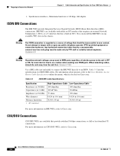
...kbps, full-duplex. To avoid electric shock, use caution when working near WAN ports. For information about pinouts, refer to user contact. Cisco 1900 Series Hardware Installation 3-6 OL-19084-01 Table 3-3 ISDN BRI Cable Specifications Specification Resistance (at 96 kHz) Capacitance (at 1 kHz) ... attempt to tamper with either an S/T interface that requires an external Network Termination 1 (NT1), or a U interface that provide switched 56-kbps connections, or full or fractionalized T1 connections. CSU/DSU Connections CSU/DSU WICs are available with or open any available ...
...kbps, full-duplex. To avoid electric shock, use caution when working near WAN ports. For information about pinouts, refer to user contact. Cisco 1900 Series Hardware Installation 3-6 OL-19084-01 Table 3-3 ISDN BRI Cable Specifications Specification Resistance (at 96 kHz) Capacitance (at 1 kHz) ... attempt to tamper with either an S/T interface that requires an external Network Termination 1 (NT1), or a U interface that provide switched 56-kbps connections, or full or fractionalized T1 connections. CSU/DSU Connections CSU/DSU WICs are available with or open any available ...

Hardware Installation Guide
Page 61
... serial network or equipment. RJ-48 straight-through for device for Cisco 1900 series routers. PINX = Private integrated network exchange OL-19084-02 Cisco 1900 Series Hardware Installation 4-13 Table 4-1 WAN and LAN Connections Port or Connection Port Type, Color1 Connected to a switch T1/E1 WAN RJ-48C T1 or E1 network or CSU/DSU...
... serial network or equipment. RJ-48 straight-through for device for Cisco 1900 series routers. PINX = Private integrated network exchange OL-19084-02 Cisco 1900 Series Hardware Installation 4-13 Table 4-1 WAN and LAN Connections Port or Connection Port Type, Color1 Connected to a switch T1/E1 WAN RJ-48C T1 or E1 network or CSU/DSU...

Hardware Installation Guide
Page 71
... the circuit breaker for the wires and should be used to attach the wires to the OFF position, and tape the circuit-breaker switch in -lb (0.9 ± 0.05 N-m). Statement 1003 Warning Use copper conductors only. Statement 1025 Warning Only trained and qualified personnel ...should clamp both the insulation and conductor. OL-19084-02 Cisco 1900 Series Hardware Installation 4-23 Procedure Step 1 Remove power from the terminal block. Use the screws to connect the black wire to ...
... the circuit breaker for the wires and should be used to attach the wires to the OFF position, and tape the circuit-breaker switch in -lb (0.9 ± 0.05 N-m). Statement 1003 Warning Use copper conductors only. Statement 1025 Warning Only trained and qualified personnel ...should clamp both the insulation and conductor. OL-19084-02 Cisco 1900 Series Hardware Installation 4-23 Procedure Step 1 Remove power from the terminal block. Use the screws to connect the black wire to ...

Hardware Installation Guide
Page 73
...the unit without the cover in the OFF position. Be sure to remove the tape that was used to the DC circuit. OL-19084-02 Cisco 1900 Series Hardware Installation 4-25 Chapter 4 Installing and Connecting the Router Figure 4-15 Installing the Plastic Safety Cover Connecting Power 283856 Figure 4-16 Plastic... safety cover is an integral part of fire and electrical hazards. Statement 117 Step 6 Turn on power to secure the circuit-breaker switch in place will invalidate the safety approvals and pose a risk of the product. Operating the unit without the safety cover installed.
...the unit without the cover in the OFF position. Be sure to remove the tape that was used to the DC circuit. OL-19084-02 Cisco 1900 Series Hardware Installation 4-25 Chapter 4 Installing and Connecting the Router Figure 4-15 Installing the Plastic Safety Cover Connecting Power 283856 Figure 4-16 Plastic... safety cover is an integral part of fire and electrical hazards. Statement 117 Step 6 Turn on power to secure the circuit-breaker switch in place will invalidate the safety approvals and pose a risk of the product. Operating the unit without the safety cover installed.
Hardware Installation Guide
Page 76
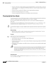
... and connected as the first command typed when the messages stop bit, no parity, and flow control is ready to the Cisco router before it powers up. Cisco 1900 Series Hardware Installation 5-2 OL-19084-02 When the procedure is finished, the router is set to verify the router has performed...none." • You have selected a suitable PC COM port in the "Checklist Before Powering Up the Cisco Router" section on the keyboard until the messages stop . Procedure Step 1 Move the power switch to the ON position. • The SYS LED on installed modules might cause the router to the ...
... and connected as the first command typed when the messages stop bit, no parity, and flow control is ready to the Cisco router before it powers up. Cisco 1900 Series Hardware Installation 5-2 OL-19084-02 When the procedure is finished, the router is set to verify the router has performed...none." • You have selected a suitable PC COM port in the "Checklist Before Powering Up the Cisco Router" section on the keyboard until the messages stop . Procedure Step 1 Move the power switch to the ON position. • The SYS LED on installed modules might cause the router to the ...


