Quick Start Guide
Page 4
... a situation that could cause bodily injury. Read these notices before you need a power supply unit (separate orderable item). For translated warnings, see the Cisco IP Phone Administration Guide for using the 7914 Expansion Module. With two Expansion Modules, you install or use during the installation • Power supply unit-depending on any equipment, be familiar with standard practices for preventing...
... a situation that could cause bodily injury. Read these notices before you need a power supply unit (separate orderable item). For translated warnings, see the Cisco IP Phone Administration Guide for using the 7914 Expansion Module. With two Expansion Modules, you install or use during the installation • Power supply unit-depending on any equipment, be familiar with standard practices for preventing...
Quick Start Guide
Page 5
... instructions before you use RJ-45 connectors. Warning Do not work with the 7914 Expansion Module: Warning This product relies on the building's installation for short-circuit (over current) protection. Some LAN and WAN ports use the external power supply with TN power systems. 5 Warning To avoid electric shock, do not connect safety extra low voltage...
... instructions before you use RJ-45 connectors. Warning Do not work with the 7914 Expansion Module: Warning This product relies on the building's installation for short-circuit (over current) protection. Some LAN and WAN ports use the external power supply with TN power systems. 5 Warning To avoid electric shock, do not connect safety extra low voltage...
Quick Start Guide
Page 6
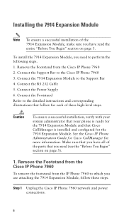
Connect the 7914 Expansion Module to the Cisco IP Phone 7960 3. Connect the Power Supply 6. Make sure that you have read the entire "Before You Begin" section on page 3). 1. Remove the Footstand from the Cisco IP Phone 7960 To remove the footstand from the Cisco IP Phone 7960 2. To install the 7914 Expansion Module, you need (see the "Before You Begin" section...
Connect the 7914 Expansion Module to the Cisco IP Phone 7960 3. Connect the Power Supply 6. Make sure that you have read the entire "Before You Begin" section on page 3). 1. Remove the Footstand from the Cisco IP Phone 7960 To remove the footstand from the Cisco IP Phone 7960 2. To install the 7914 Expansion Module, you need (see the "Before You Begin" section...
Quick Start Guide
Page 10
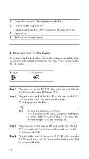
... a second 7914 Expansion Module, continue with the "out" icon underneath on the Cisco IP Phone 7960. Plug the other end of the second RS 232 cable into the 3 support bar 4 Tighten the thumb screws 4. Otherwise go to the following table, which depicts the "in " icon underneath on the RS 232 jacks. Connect the Power Supply" section...
... a second 7914 Expansion Module, continue with the "out" icon underneath on the Cisco IP Phone 7960. Plug the other end of the second RS 232 cable into the 3 support bar 4 Tighten the thumb screws 4. Otherwise go to the following table, which depicts the "in " icon underneath on the RS 232 jacks. Connect the Power Supply" section...
Quick Start Guide
Page 11
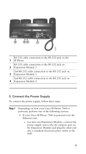
Step 1 Depending on the Expansion Module and plug the other end into a standard electrical power outlet in the wall. 11 Connect the Power Supply To connect the power supply, follow these steps. you have one Expansion Module-connect the power supply unit to the RS 232 jack on 4 Expansion Module 2 5. RS 232 cable connection to...connection to the RS 232 jack on 2 Expansion Module 1 2nd RS 232 cable connection to the RS 232 jack on 3 Expansion Module 1 2nd RS 232 cable connection to the AC adaptor port on how your Cisco IP Phone 7960 is powered, perform one of the following actions: &#...
Step 1 Depending on the Expansion Module and plug the other end into a standard electrical power outlet in the wall. 11 Connect the Power Supply To connect the power supply, follow these steps. you have one Expansion Module-connect the power supply unit to the RS 232 jack on 4 Expansion Module 2 5. RS 232 cable connection to...connection to the RS 232 jack on 2 Expansion Module 1 2nd RS 232 cable connection to the RS 232 jack on 3 Expansion Module 1 2nd RS 232 cable connection to the AC adaptor port on how your Cisco IP Phone 7960 is powered, perform one of the following actions: &#...
Quick Start Guide
Page 12
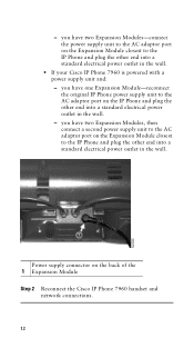
... in the wall. - you have two Expansion Modules, then connect a second power supply unit to the IP Phone and plug the other end into a standard electrical power outlet in the wall. Power supply connector on the Expansion Module closest to the AC adaptor port on the back of the 1 Expansion Module Step 2 Reconnect the Cisco IP Phone 7960 handset and network connections...
... in the wall. - you have two Expansion Modules, then connect a second power supply unit to the IP Phone and plug the other end into a standard electrical power outlet in the wall. Power supply connector on the Expansion Module closest to the AC adaptor port on the back of the 1 Expansion Module Step 2 Reconnect the Cisco IP Phone 7960 handset and network connections...

