Quick Start Guide
Page 1
Quick Start Guide Cisco IP Phone 7914 Expansion Module 1 Introduction to the Cisco IP Phone 7914 Expansion Module 2 Installing the 7914 Expansion Module 3 Features 4 How to Use the 7914 Expansion Module 5 Troubleshooting 6 Technical Specifications 7 For More Information 8 Obtaining Technical Assistance
Quick Start Guide Cisco IP Phone 7914 Expansion Module 1 Introduction to the Cisco IP Phone 7914 Expansion Module 2 Installing the 7914 Expansion Module 3 Features 4 How to Use the 7914 Expansion Module 5 Troubleshooting 6 Technical Specifications 7 For More Information 8 Obtaining Technical Assistance
Quick Start Guide
Page 2
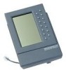
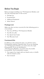
... the Cisco IP Phone 7914 Expansion Module The Cisco IP Phone 7914 Expansion Module attaches to your Cisco IP Phone 7960, adding 14 line appearances and/or speed dial numbers to safely install your 7914 Expansion Module. • Before You Begin • Installing the 7914 Expansion Module 2 Read all of 34 line appearances and/or speed dial numbers. 2 Installing the 7914 Expansion Module You can attach one or two 7914 Expansion Modules to your IP Phone. When you use two Expansion Modules, you have 28 additional line appearances and/or speed dial numbers, or...
... the Cisco IP Phone 7914 Expansion Module The Cisco IP Phone 7914 Expansion Module attaches to your Cisco IP Phone 7960, adding 14 line appearances and/or speed dial numbers to safely install your 7914 Expansion Module. • Before You Begin • Installing the 7914 Expansion Module 2 Read all of 34 line appearances and/or speed dial numbers. 2 Installing the 7914 Expansion Module You can attach one or two 7914 Expansion Modules to your IP Phone. When you use two Expansion Modules, you have 28 additional line appearances and/or speed dial numbers, or...
Quick Start Guide
Page 3
... Begin Before you begin installing your 7914 Expansion Module, read all of the following topics in your package: • One Cisco IP Phone 7914 Expansion Module • One RS 232 cable • One Quick Start Guide • One Warranty Card Footstand Kits In addition to the package list items, you will also need to have received all of the following parts in this section: •...
... Begin Before you begin installing your 7914 Expansion Module, read all of the following topics in your package: • One Cisco IP Phone 7914 Expansion Module • One RS 232 cable • One Quick Start Guide • One Warranty Card Footstand Kits In addition to the package list items, you will also need to have received all of the following parts in this section: •...
Quick Start Guide
Page 4
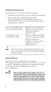
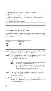
... Expansion Module, no power supply unit needed. Read these notices before you install or use during the installation • Power supply unit-depending on any equipment, be aware of a non-Cisco certified power supply unit may not work on how many Expansion Modules you need a power supply unit (separate orderable item). For translated warnings, see the Cisco IP Phone Administration Guide for preventing accidents. 4 Warning This warning symbol means danger. Additional...
... Expansion Module, no power supply unit needed. Read these notices before you install or use during the installation • Power supply unit-depending on any equipment, be aware of a non-Cisco certified power supply unit may not work on how many Expansion Modules you need a power supply unit (separate orderable item). For translated warnings, see the Cisco IP Phone Administration Guide for preventing accidents. 4 Warning This warning symbol means danger. Additional...
Quick Start Guide
Page 5
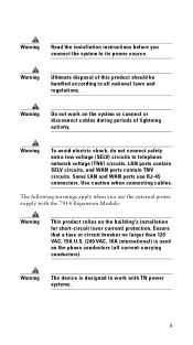
... connect safety extra low voltage (SELV) circuits to all current-carrying conductors). LAN ports contain SELV circuits, and WAN ports contain TNV circuits. Warning Read the installation instructions before you use RJ-45 connectors. The following warnings apply when you connect the system to work on the building's installation for short-circuit (over current) protection. Warning Do not work with the 7914 Expansion Module...
... connect safety extra low voltage (SELV) circuits to all current-carrying conductors). LAN ports contain SELV circuits, and WAN ports contain TNV circuits. Warning Read the installation instructions before you use RJ-45 connectors. The following warnings apply when you connect the system to work on the building's installation for short-circuit (over current) protection. Warning Do not work with the 7914 Expansion Module...
Quick Start Guide
Page 6
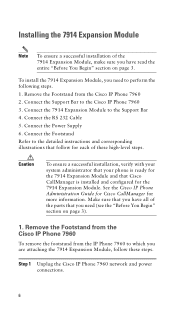
... Guide for Cisco CallManager for the 7914 Expansion Module. Connect the Support Bar to the Support Bar 4. Step 1 Unplug the Cisco IP Phone 7960 network and power connections. 6 Installing the 7914 Expansion Module Note To ensure a successful installation of the 7914 Expansion Module, make sure you have all of these steps. Make sure that you have read the entire "Before You Begin" section on page 3). 1. Remove the Footstand from the IP Phone 7960 to the detailed instructions...
... Guide for Cisco CallManager for the 7914 Expansion Module. Connect the Support Bar to the Support Bar 4. Step 1 Unplug the Cisco IP Phone 7960 network and power connections. 6 Installing the 7914 Expansion Module Note To ensure a successful installation of the 7914 Expansion Module, make sure you have all of these steps. Make sure that you have read the entire "Before You Begin" section on page 3). 1. Remove the Footstand from the IP Phone 7960 to the detailed instructions...
Quick Start Guide
Page 8
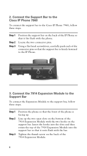
... phone. Connect the 7914 Expansion Module to the Support Bar To connect the Expansion Module to the Cisco IP Phone 7960, follow these steps. 2. Insert the hooks into the slots and then rotate the top of the IP Phone so that it fits flush with the bar. Locate the two connector pins. Line up . Connect the Support Bar to the Cisco IP Phone 7960 To connect the support bar to the support...
... phone. Connect the 7914 Expansion Module to the Support Bar To connect the Expansion Module to the Cisco IP Phone 7960, follow these steps. 2. Insert the hooks into the slots and then rotate the top of the IP Phone so that it fits flush with the bar. Locate the two connector pins. Line up . Connect the Support Bar to the Cisco IP Phone 7960 To connect the support bar to the support...
Quick Start Guide
Page 10
1 Open slots on the 7914 Expansion Module 2 Hooks on the support bar Insert and rotate the 7914 Expansion Module into the RS 232 jack with the "in" icon underneath on the 2nd Expansion Module. 10 Plug the other end...installing a second 7914 Expansion Module, continue with the "out" icon underneath on the 7914 Expansion Module. Plug the other end of the second RS 232 cable into the RS 232 jack with Steps 3 and 4. Otherwise go to the following table, which depicts the "in " icon underneath on the 1st Expansion Module. Connect the Power Supply" section on the Cisco IP Phone...
1 Open slots on the 7914 Expansion Module 2 Hooks on the support bar Insert and rotate the 7914 Expansion Module into the RS 232 jack with the "in" icon underneath on the 2nd Expansion Module. 10 Plug the other end...installing a second 7914 Expansion Module, continue with the "out" icon underneath on the 7914 Expansion Module. Plug the other end of the second RS 232 cable into the RS 232 jack with Steps 3 and 4. Otherwise go to the following table, which depicts the "in " icon underneath on the 1st Expansion Module. Connect the Power Supply" section on the Cisco IP Phone...
Quick Start Guide
Page 12
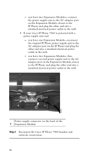
... 1 Expansion Module Step 2 Reconnect the Cisco IP Phone 7960 handset and network connections. 12 you have two Expansion Modules, then connect a second power supply unit to the AC adaptor port on the Expansion Module closest to the IP Phone and plug the other end into a standard electrical power outlet in the wall. • If your Cisco IP Phone 7960 is powered with a power supply unit and: - - you have two Expansion Modules-connect the power supply unit to the AC adaptor port...
... 1 Expansion Module Step 2 Reconnect the Cisco IP Phone 7960 handset and network connections. 12 you have two Expansion Modules, then connect a second power supply unit to the AC adaptor port on the Expansion Module closest to the IP Phone and plug the other end into a standard electrical power outlet in the wall. • If your Cisco IP Phone 7960 is powered with a power supply unit and: - - you have two Expansion Modules-connect the power supply unit to the AC adaptor port...
Quick Start Guide
Page 14
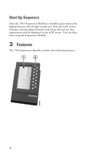
Start Up Sequence After the 7914 Expansion Module is installed, upon startup the lighted buttons will be displayed in the LCD screen. Then the LCD screen refreshes and the lighted buttons will all go off and any line appearances will all light steady red. You can then start using the Expansion Module. 3 Features The 7914 Expansion Module includes the following features. 14
Start Up Sequence After the 7914 Expansion Module is installed, upon startup the lighted buttons will be displayed in the LCD screen. Then the LCD screen refreshes and the lighted buttons will all go off and any line appearances will all light steady red. You can then start using the Expansion Module. 3 Features The 7914 Expansion Module includes the following features. 14
Quick Start Guide
Page 15
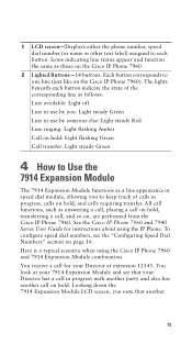
... a call for instructions about using the Cisco IP Phone 7960 and 7914 Expansion Module combination. Icons indicating line status appear and function the same as a line appearance or speed dial module, allowing you to keep track of calls in progress, calls on hold , transferring a call on page 16. Looking down the 7914 Expansion Module LCD screen, you : Light steady Green Line in use by someone else: Light steady Red Line ringing: Light flashing Amber Call on hold: Light flashing Green Call transfer: Light steady Green 4 How to Use the 7914 Expansion Module The 7914 Expansion Module...
... a call for instructions about using the Cisco IP Phone 7960 and 7914 Expansion Module combination. Icons indicating line status appear and function the same as a line appearance or speed dial module, allowing you to keep track of calls in progress, calls on hold , transferring a call on page 16. Looking down the 7914 Expansion Module LCD screen, you : Light steady Green Line in use by someone else: Light steady Red Line ringing: Light flashing Amber Call on hold: Light flashing Green Call transfer: Light steady Green 4 How to Use the 7914 Expansion Module The 7914 Expansion Module...
Quick Start Guide
Page 16
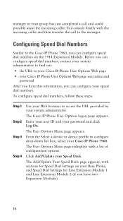
... Base Phone, and Speed Dial Settings for Speed Dial Settings on the 7914 Expansion Module. The User Options Menu page redisplays with sections for Line Extension Module 1 and Line Extension Module 2 (if you have this information, you have two Expansion Modules). 16 To configure speed dial numbers, follow these steps. The User Options Menu page appears. You consult briefly with the incoming caller and then transfer the call and could possibly assist the incoming caller. The Add/Update Your Speed Dials page appears, with a list of configuration options. The Cisco IP Phone User...
... Base Phone, and Speed Dial Settings for Speed Dial Settings on the 7914 Expansion Module. The User Options Menu page redisplays with sections for Line Extension Module 1 and Line Extension Module 2 (if you have this information, you have two Expansion Modules). 16 To configure speed dial numbers, follow these steps. The User Options Menu page appears. You consult briefly with the incoming caller and then transfer the call and could possibly assist the incoming caller. The Add/Update Your Speed Dials page appears, with a list of configuration options. The Cisco IP Phone User...
Quick Start Guide
Page 17
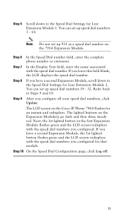
... speed dial numbers 5 - 18. The lighted buttons on the 7914 Expansion Module. Step 10 On the Speed Dial Configuration page, click Log off. 17 Refer back to the Speed Dial Settings for Line Extension Module 1. The LCD screen on the first Expansion Module flashes green and the LCD screen redisplays with the speed dial numbers you have a second Expansion Module, scroll down to Steps 9 and 10. If you configure all your speed dial numbers, click Update. If you configured. Step 6 In the Speed Dial number field, enter the complete phone number...
... speed dial numbers 5 - 18. The lighted buttons on the 7914 Expansion Module. Step 10 On the Speed Dial Configuration page, click Log off. 17 Refer back to the Speed Dial Settings for Line Extension Module 1. The LCD screen on the first Expansion Module flashes green and the LCD screen redisplays with the speed dial numbers you have a second Expansion Module, scroll down to Steps 9 and 10. If you configure all your speed dial numbers, click Update. If you configured. Step 6 In the Speed Dial number field, enter the complete phone number...
Quick Start Guide
Page 18
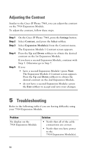
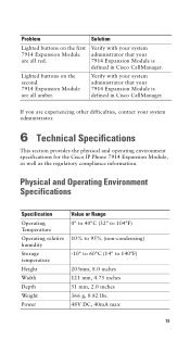
.... Problem No display on the 7914 Expansion Module Solution • Verify that all of the cable connections are having difficulty using your changes. 5 Troubleshooting Refer to the following table if you can adjust the contrast on the 7914 Expansion Module. Adjusting the Contrast Similar to obtain the desired contrast on the 1st Expansion Module. The Expansion Module 1 Contrast screen appears. Press the Up and Down softkeys to the Cisco IP Phone 7960...
.... Problem No display on the 7914 Expansion Module Solution • Verify that all of the cable connections are having difficulty using your changes. 5 Troubleshooting Refer to the following table if you can adjust the contrast on the 7914 Expansion Module. Adjusting the Contrast Similar to obtain the desired contrast on the 1st Expansion Module. The Expansion Module 1 Contrast screen appears. Press the Up and Down softkeys to the Cisco IP Phone 7960...
Quick Start Guide
Page 19
... 7914 Expansion Module are experiencing other difficulties, contact your 7914 Expansion Module is defined in Cisco CallManager. Verify with your system administrator that your system administrator. 6 Technical Specifications This section provides the physical and operating environment specifications for the Cisco IP Phone 7914 Expansion Module, as well as the regulatory compliance information. Physical and Operating Environment Specifications Specification Operating Temperature Operating relative humidity Storage temperature Height Width Depth Weight Power Value or Range...
... 7914 Expansion Module are experiencing other difficulties, contact your 7914 Expansion Module is defined in Cisco CallManager. Verify with your system administrator that your system administrator. 6 Technical Specifications This section provides the physical and operating environment specifications for the Cisco IP Phone 7914 Expansion Module, as well as the regulatory compliance information. Physical and Operating Environment Specifications Specification Operating Temperature Operating relative humidity Storage temperature Height Width Depth Weight Power Value or Range...
Quick Start Guide
Page 21
... • Cisco IP Phone 7960 and 7940 Series User Guide-Provides instructions to configure IP Phones and services. 7 For More Information The following documents provide additional information. • Cisco IP Phone Administration Guide for Cisco CallManager-Provides instructions for the system administrator about configuring the 7914 Expansion Module in Cisco CallManager. http://www.cisco.com/univercd/cc/td/doc/product/voice/ c_ipphon/index.htm • Cisco CallManager documentation-Provides instructions for using the Cisco CallManager Administration...
... • Cisco IP Phone 7960 and 7940 Series User Guide-Provides instructions to configure IP Phones and services. 7 For More Information The following documents provide additional information. • Cisco IP Phone Administration Guide for Cisco CallManager-Provides instructions for the system administrator about configuring the 7914 Expansion Module in Cisco CallManager. http://www.cisco.com/univercd/cc/td/doc/product/voice/ c_ipphon/index.htm • Cisco CallManager documentation-Provides instructions for using the Cisco CallManager Administration...

Quick Start Guide
Page 22
... these ways: • Registered Cisco.com users (Cisco direct customers) can order Cisco product documentation from the Networking Products MarketPlace: http://www.cisco.com/cgi-bin/order/order_root.pl • Registered Cisco.com users can order the Documentation CD-ROM through an annual subscription. You can submit comments electronically on Cisco.com. The Documentation CD-ROM is available as a single unit or through the online...
... these ways: • Registered Cisco.com users (Cisco direct customers) can order Cisco product documentation from the Networking Products MarketPlace: http://www.cisco.com/cgi-bin/order/order_root.pl • Registered Cisco.com users can order the Documentation CD-ROM through an annual subscription. You can submit comments electronically on Cisco.com. The Documentation CD-ROM is available as a single unit or through the online...

Quick Start Guide
Page 23
... a starting point for all customers who need technical assistance with online support • Download and test software packages • Order Cisco learning materials and merchandise • Register for online skill assessment, training, and certification programs If you want to obtain customized information and service, you can obtain online documentation, troubleshooting tips, and sample configurations from anywhere in the world. Cisco.com registered users have complete access...
... a starting point for all customers who need technical assistance with online support • Download and test software packages • Order Cisco learning materials and merchandise • Register for online skill assessment, training, and certification programs If you want to obtain customized information and service, you can obtain online documentation, troubleshooting tips, and sample configurations from anywhere in the world. Cisco.com registered users have complete access...

Quick Start Guide
Page 24
... information or assistance concerning Cisco product capabilities, product installation, or basic product configuration. • Priority level 3 (P3)-Your network performance is not restored quickly. No workaround is available. • Priority level 1 (P1)-Your production network is down, and a critical impact to business operations will occur if service is degraded. Cisco TAC Web Site You can open a case online by using the TAC Case...
... information or assistance concerning Cisco product capabilities, product installation, or basic product configuration. • Priority level 3 (P3)-Your network performance is not restored quickly. No workaround is available. • Priority level 1 (P1)-Your production network is down, and a critical impact to business operations will occur if service is degraded. Cisco TAC Web Site You can open a case online by using the TAC Case...

Quick Start Guide
Page 25
... The Cisco TAC Escalation Center addresses priority level 1 or priority level 2 issues. To obtain a directory of toll-free Cisco TAC telephone numbers for your country, go to this URL: http://www.cisco.com/warp/public/687/Directory/DirTAC.shtml Before calling, please check with a P1 or P2 problem, a Cisco TAC engineer automatically opens a case. When you contact the TAC Escalation Center with your network operations center...
... The Cisco TAC Escalation Center addresses priority level 1 or priority level 2 issues. To obtain a directory of toll-free Cisco TAC telephone numbers for your country, go to this URL: http://www.cisco.com/warp/public/687/Directory/DirTAC.shtml Before calling, please check with a P1 or P2 problem, a Cisco TAC engineer automatically opens a case. When you contact the TAC Escalation Center with your network operations center...


