
Installation Guide
Page 2
...FULL RESPONSIBILITY FOR THEIR APPLICATION OF ANY PRODUCTS. could void the FCC approval and negate your equipment is operated in accordance with the specifications in the equipment no guarantee that is on a different circuit from the television or radio. (That is, make certain the ... are on circuits controlled by the Cisco equipment or one side or the other of Class A devices: This equipment has been tested and found to comply with radio and television reception. These specifications are designed to radio communications. THE SPECIFICATIONS AND INFORMATION REGARDING THE PRODUCTS IN ...
...FULL RESPONSIBILITY FOR THEIR APPLICATION OF ANY PRODUCTS. could void the FCC approval and negate your equipment is operated in accordance with the specifications in the equipment no guarantee that is on a different circuit from the television or radio. (That is, make certain the ... are on circuits controlled by the Cisco equipment or one side or the other of Class A devices: This equipment has been tested and found to comply with radio and television reception. These specifications are designed to radio communications. THE SPECIFICATIONS AND INFORMATION REGARDING THE PRODUCTS IN ...

Installation Guide
Page 8
... B-1 1000BaseX Ports B-2 Gigastack Port B-3 Console Port B-3 Cable and Adapter Specifications B-4 Crossover and Straight-Through Cable Pinouts B-4 Rollover Cable and Adapter Pinouts B-5 Identifying a Rollover Cable B-5 Connecting to a PC B-6 Connecting to a Terminal B-7 Translated Safety Warnings C-1 Attaching the Cisco RPS (model PWR600-AC-RPS) C-2 Attaching the Cisco RPS (model PWR300-AC-RPS-N1) C-4 Service Personnel Warning...
... B-1 1000BaseX Ports B-2 Gigastack Port B-3 Console Port B-3 Cable and Adapter Specifications B-4 Crossover and Straight-Through Cable Pinouts B-4 Rollover Cable and Adapter Pinouts B-5 Identifying a Rollover Cable B-5 Connecting to a PC B-6 Connecting to a Terminal B-7 Translated Safety Warnings C-1 Attaching the Cisco RPS (model PWR600-AC-RPS) C-2 Attaching the Cisco RPS (model PWR300-AC-RPS-N1) C-4 Service Personnel Warning...

Installation Guide
Page 12
... C, "Translated Safety Warnings," contains translations in various languages of the switch. Catalyst 3500 Series XL Hardware Installation Guide xii 78-6456-04 Chapter 2, "Installing and Starting Up the Switch," contains the procedures for the switches and the regulatory agency approvals. Appendix B, "Connector and Cable Specifications," describes the connectors, cables, and adapters that might arise when...
... C, "Translated Safety Warnings," contains translations in various languages of the switch. Catalyst 3500 Series XL Hardware Installation Guide xii 78-6456-04 Chapter 2, "Installing and Starting Up the Switch," contains the procedures for the switches and the regulatory agency approvals. Appendix B, "Connector and Cable Specifications," describes the connectors, cables, and adapters that might arise when...

Installation Guide
Page 25
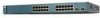
A feature specific to the Catalyst 3524-PWR XL switch is its ability to provide inline power to Cisco IP Phones. (Phone adapters are stackable 10/100 Ethernet switches to the Catalyst 3524-PWR XL 10/100 switch ports.) Figure 1-1 shows the switch models in the series, and Table 1-1 and Table 1-2 list their features. 78-6456-04 Catalyst 3500 Series XL...
A feature specific to the Catalyst 3524-PWR XL switch is its ability to provide inline power to Cisco IP Phones. (Phone adapters are stackable 10/100 Ethernet switches to the Catalyst 3524-PWR XL 10/100 switch ports.) Figure 1-1 shows the switch models in the series, and Table 1-1 and Table 1-2 list their features. 78-6456-04 Catalyst 3500 Series XL...

Installation Guide
Page 32
... inline power settings for Cisco IP Phones. Cisco IP Phones-connected to the 10/100 ports on a port, the port Catalyst 3500 Series XL Hardware Installation Guide 1-8 78-6456-04 When you can use a crossover cable. The 10/100 switch ports can be connected to operate in Appendix B, "Connector and Cable Specifications." Ports operating at...
... inline power settings for Cisco IP Phones. Cisco IP Phones-connected to the 10/100 ports on a port, the port Catalyst 3500 Series XL Hardware Installation Guide 1-8 78-6456-04 When you can use a crossover cable. The 10/100 switch ports can be connected to operate in Appendix B, "Connector and Cable Specifications." Ports operating at...

Installation Guide
Page 47
... a one-to the four DC output power modules. Cisco RPS Connector Specific Cisco RPS models support specific Catalyst 3500 XL switches: • Cisco RPS 600 (model PWR600-AC-RPS)-Supports the Catalyst 3512, 3524, 3548, and 3508 XL switches • Cisco RPS 300 (model PWR300-AC-RPS)-Supports the Catalyst 3524-PWR XL switch RPS Connector on RPS. Warning Attach only the...
... a one-to the four DC output power modules. Cisco RPS Connector Specific Cisco RPS models support specific Catalyst 3500 XL switches: • Cisco RPS 600 (model PWR600-AC-RPS)-Supports the Catalyst 3512, 3524, 3548, and 3508 XL switches • Cisco RPS 300 (model PWR300-AC-RPS)-Supports the Catalyst 3524-PWR XL switch RPS Connector on RPS. Warning Attach only the...

Installation Guide
Page 48
...-DB-25 female DTE adapter if you use to the Cisco Redundant Power System 300 Hardware Installation Guide. For console port and adapter pinout information, see the "Cable and Adapter Specifications" section on the Catalyst 3524-PWR XL Switch The Cisco RPS 300 (model PWR300-AC-RPS) has two output ...levels: -48V and 12V with a total output power of 300W. For more information on the Cisco RPS 300, refer to create, monitor, and...
...-DB-25 female DTE adapter if you use to the Cisco Redundant Power System 300 Hardware Installation Guide. For console port and adapter pinout information, see the "Cable and Adapter Specifications" section on the Catalyst 3524-PWR XL Switch The Cisco RPS 300 (model PWR300-AC-RPS) has two output ...levels: -48V and 12V with a total output power of 300W. For more information on the Cisco RPS 300, refer to create, monitor, and...

Installation Guide
Page 65
...-6456-04 Catalyst 3500 Series XL Hardware Installation Guide 2-7 For specific cable lengths, refer to the documents that came with the GigaStack GBIC. • Operating environment is a class A product and should be sure to observe these guidelines: • For 10/100 ports, cable lengths from the switch to connected devices are up to...
...-6456-04 Catalyst 3500 Series XL Hardware Installation Guide 2-7 For specific cable lengths, refer to the documents that came with the GigaStack GBIC. • Operating environment is a class A product and should be sure to observe these guidelines: • For 10/100 ports, cable lengths from the switch to connected devices are up to...

Installation Guide
Page 81
... these steps to connect the PC or terminal to the switch: Step 1 Step 2 Be sure that adapter from Cisco. For console port and adapter pinout information, see the "Cable and Adapter Specifications" section on the GigaStack GBIC connections and configuration scenarios, see the Catalyst GigaStack Gigabit Interface Converter Hardware Installation Guide. Chapter 2 Installing and...
... these steps to connect the PC or terminal to the switch: Step 1 Step 2 Be sure that adapter from Cisco. For console port and adapter pinout information, see the "Cable and Adapter Specifications" section on the GigaStack GBIC connections and configuration scenarios, see the Catalyst GigaStack Gigabit Interface Converter Hardware Installation Guide. Chapter 2 Installing and...

Installation Guide
Page 84
... this procedure to create an initial configuration for the switch, and press Return: 2-26 Catalyst 3500 Series XL Hardware Installation Guide 78-6456-04 You can order a kit (part number ACS-DSBUASYN=) containing that adapter from Cisco. Use the supplied rollover cable and DB-9 adapter ...to connect a PC to restart the setup program. For console port and adapter pinout information, see the "Cable and Adapter Specifications" section on page B-4. Assigning Switch Information Chapter 2 Installing and Starting Up the Switch ...
... this procedure to create an initial configuration for the switch, and press Return: 2-26 Catalyst 3500 Series XL Hardware Installation Guide 78-6456-04 You can order a kit (part number ACS-DSBUASYN=) containing that adapter from Cisco. Use the supplied rollover cable and DB-9 adapter ...to connect a PC to restart the setup program. For console port and adapter pinout information, see the "Cable and Adapter Specifications" section on page B-4. Assigning Switch Information Chapter 2 Installing and Starting Up the Switch ...

Installation Guide
Page 97
Table A-4 lists the regulatory agency approvals. A A P P E N D I X Technical Specifications 78-6456-04 Table A-1, Table A-2, and Table A-3, list the technical specifications for the Catalyst 3508G XL Switch Environmental Ranges Operating temperature Storage temperature Operating humidity Operating altitude Storage altitude Power Requirements AC input voltage DC ...3A 82.2W 280 Btus per hour 12 lb (5.45 kg) 1.75 x 16 x 17.5 in. (4.45 x 40.46 x 44.45 cm) Catalyst 3500 Series XL Hardware Installation Guide A-1 Table A-1 Technical Specifications for the Catalyst 3500 series XL switches.
Table A-4 lists the regulatory agency approvals. A A P P E N D I X Technical Specifications 78-6456-04 Table A-1, Table A-2, and Table A-3, list the technical specifications for the Catalyst 3508G XL Switch Environmental Ranges Operating temperature Storage temperature Operating humidity Operating altitude Storage altitude Power Requirements AC input voltage DC ...3A 82.2W 280 Btus per hour 12 lb (5.45 kg) 1.75 x 16 x 17.5 in. (4.45 x 40.46 x 44.45 cm) Catalyst 3500 Series XL Hardware Installation Guide A-1 Table A-1 Technical Specifications for the Catalyst 3500 series XL switches.

Installation Guide
Page 98
Appendix A Technical Specifications Table A-2 Technical Specifications for the Catalyst 3512, 3524, and 3548 XL Switches Catalyst 3512 XL Catalyst 3524 XL Catalyst 3548 XL Environmental Ranges Operating temperature 32 to 113°F (0 to 45°C) 32 to 113°F (0 to 45°C) 32 to 113°F (0 to ....82 x 17.5 in. 1.73 x 15.34 x 17.5 in D x W) (4.45 x 30.02 x 44.45 cm) (4.45 x 30.02 x 44.45 cm) (4.39 x 39.0 x 44.45 cm) Catalyst 3500 Series XL Hardware Installation Guide A-2 78-6456-04
Appendix A Technical Specifications Table A-2 Technical Specifications for the Catalyst 3512, 3524, and 3548 XL Switches Catalyst 3512 XL Catalyst 3524 XL Catalyst 3548 XL Environmental Ranges Operating temperature 32 to 113°F (0 to 45°C) 32 to 113°F (0 to 45°C) 32 to 113°F (0 to ....82 x 17.5 in. 1.73 x 15.34 x 17.5 in D x W) (4.45 x 30.02 x 44.45 cm) (4.45 x 30.02 x 44.45 cm) (4.39 x 39.0 x 44.45 cm) Catalyst 3500 Series XL Hardware Installation Guide A-2 78-6456-04

Installation Guide
Page 99
Appendix A Technical Specifications Table A-3 Technical Specifications for the Catalyst 3524-PWR XL Switch Environmental Ranges Operating temperature 32 to 113°F (0 to 45°C) Storage temperature -4 to 149°F (-10 to 65°C) Operating humidity 10 to 85% (... Power consumption 100 to 127/200 to 240 VAC (autoranging) 50 to NOM-019-SCFI CE Marking CE Marking 78-6456-04 Catalyst 3500 Series XL Hardware Installation Guide A-3 Table A-4 Catalyst 3500 Series XL Agency Approvals Safety EMC UL to UL 1950, Third Edition FCC Part 15 Class A c-UL to CAN/CSA...
Appendix A Technical Specifications Table A-3 Technical Specifications for the Catalyst 3524-PWR XL Switch Environmental Ranges Operating temperature 32 to 113°F (0 to 45°C) Storage temperature -4 to 149°F (-10 to 65°C) Operating humidity 10 to 85% (... Power consumption 100 to 127/200 to 240 VAC (autoranging) 50 to NOM-019-SCFI CE Marking CE Marking 78-6456-04 Catalyst 3500 Series XL Hardware Installation Guide A-3 Table A-4 Catalyst 3500 Series XL Agency Approvals Safety EMC UL to UL 1950, Third Edition FCC Part 15 Class A c-UL to CAN/CSA...

Installation Guide
Page 100
Appendix A Technical Specifications Catalyst 3500 Series XL Hardware Installation Guide A-4 78-6456-04
Appendix A Technical Specifications Catalyst 3500 Series XL Hardware Installation Guide A-4 78-6456-04

Installation Guide
Page 101
APPENDIX B Connector and Cable Specifications This appendix describes the Catalyst 3500 XL switch ports and the cables and adapters that you must use a straight-through cable wired for 10BaseT and 100BaseTX (Figure B-5 illustrates the straight-through cable schematics). When connecting the 10/100 ports to compatible workstations, servers, routers, and Cisco IP Phones, you use...
APPENDIX B Connector and Cable Specifications This appendix describes the Catalyst 3500 XL switch ports and the cables and adapters that you must use a straight-through cable wired for 10BaseT and 100BaseTX (Figure B-5 illustrates the straight-through cable schematics). When connecting the 10/100 ports to compatible workstations, servers, routers, and Cisco IP Phones, you use...

Installation Guide
Page 102
Figure B-2 1000BaseX SC Connector H8707 Tx Rx Catalyst 3500 Series XL Hardware Installation Guide B-2 78-6456-04 Connector Specifications Appendix B Connector and Cable Specifications Figure B-1 10/100 Port Pinouts Pin Label 1 RD+ 2 RD- 3 TD+ 4 NC 5 NC 6 TD- 7 NC 8 NC 12345678 H5318 1000BaseX Ports 1000BaseX ports use duplex SC connectors, as shown in Figure B-2.
Figure B-2 1000BaseX SC Connector H8707 Tx Rx Catalyst 3500 Series XL Hardware Installation Guide B-2 78-6456-04 Connector Specifications Appendix B Connector and Cable Specifications Figure B-1 10/100 Port Pinouts Pin Label 1 RD+ 2 RD- 3 TD+ 4 NC 5 NC 6 TD- 7 NC 8 NC 12345678 H5318 1000BaseX Ports 1000BaseX ports use duplex SC connectors, as shown in Figure B-2.

Installation Guide
Page 103
...to connect the switch console port to a console PC. Console Port The console port uses an 8-pin RJ-45 connector, described in Figure B-3. You can order a kit (part number ACS-DSBUASYN=) containing that adapter from Cisco. Appendix B Connector and Cable Specifications Connector Specifications Gigastack Port ...Figure B-3 GigaStack Connector 22084 The GigaStack GBIC cables are used to connect the console port of the switch to a terminal. For console port and adapter pinout information, see Table B-1 and Table B-2. 78-6456-04 Catalyst 3500 Series XL Hardware Installation Guide B-3
...to connect the switch console port to a console PC. Console Port The console port uses an 8-pin RJ-45 connector, described in Figure B-3. You can order a kit (part number ACS-DSBUASYN=) containing that adapter from Cisco. Appendix B Connector and Cable Specifications Connector Specifications Gigastack Port ...Figure B-3 GigaStack Connector 22084 The GigaStack GBIC cables are used to connect the console port of the switch to a terminal. For console port and adapter pinout information, see Table B-1 and Table B-2. 78-6456-04 Catalyst 3500 Series XL Hardware Installation Guide B-3

Installation Guide
Page 104
Switch 3 RD+ 6 RD- 1 RD+ 2 RD- 1 TD+ 2 TD- Switch 3 TD+ 6 TD- 1 RD+ 2 RD- 1 RD+ 2 RD- H5578 Catalyst 3500 Series XL Hardware Installation Guide B-4 78-6456-04 Cable and Adapter Specifications Appendix B Connector and Cable Specifications Cable and Adapter Specifications Crossover and Straight-Through Cable Pinouts The schematics of crossover and straight-through cables are shown in Figure B-4 and Figure B-5. H5579 Figure B-5 Straight-Through Cable Schematic Switch 3 TD+ 6 TD- Figure B-4 Crossover Cable Schematic Switch 3 TD+ 6 TD-
Switch 3 RD+ 6 RD- 1 RD+ 2 RD- 1 TD+ 2 TD- Switch 3 TD+ 6 TD- 1 RD+ 2 RD- 1 RD+ 2 RD- H5578 Catalyst 3500 Series XL Hardware Installation Guide B-4 78-6456-04 Cable and Adapter Specifications Appendix B Connector and Cable Specifications Cable and Adapter Specifications Crossover and Straight-Through Cable Pinouts The schematics of crossover and straight-through cables are shown in Figure B-4 and Figure B-5. H5579 Figure B-5 Straight-Through Cable Schematic Switch 3 TD+ 6 TD- Figure B-4 Crossover Cable Schematic Switch 3 TD+ 6 TD-

Installation Guide
Page 105
Pin 8 H10632 78-6456-04 Catalyst 3500 Series XL Hardware Installation Guide B-5 Figure B-6 Identifying a Rollover Cable Pin 1 Pin 1 on one connector and pin 8 on the outside of the cable. The wire ... other connector should be the same color. Hold the cable ends side-by-side, with the tab at the back. Appendix B Connector and Cable Specifications Cable and Adapter Specifications Rollover Cable and Adapter Pinouts Identifying a Rollover Cable To identify a rollover cable, compare the two modular ends of the right plug (see Figure...
Pin 8 H10632 78-6456-04 Catalyst 3500 Series XL Hardware Installation Guide B-5 Figure B-6 Identifying a Rollover Cable Pin 1 Pin 1 on one connector and pin 8 on the outside of the cable. The wire ... other connector should be the same color. Hold the cable ends side-by-side, with the tab at the back. Appendix B Connector and Cable Specifications Cable and Adapter Specifications Rollover Cable and Adapter Pinouts Identifying a Rollover Cable To identify a rollover cable, compare the two modular ends of the right plug (see Figure...

Installation Guide
Page 106
... 5 3 4 7 Console Device Signal CTS DSR RxD GND GND TxD DTR RTS Catalyst 3500 Series XL Hardware Installation Guide B-6 78-6456-04 Figure B-7 Connecting the Console Port to a PC PC Catalyst 3500 series XL switch 22003 RJ-45-to-RJ-45 rollover cable RJ-45-to-DB-9 adapter (labeled TERMINAL...Not connected 2 7 TxD 3 6 GND 4 5 GND 5 4 RxD 6 3 Not connected 7 2 CTS 8 1 RJ-45-to a PC. Cable and Adapter Specifications Appendix B Connector and Cable Specifications Connecting to a PC Use the supplied thin, flat, RJ-45-to-RJ-45 rollover cable and RJ-45-to-DB-9 female DTE adapter...
... 5 3 4 7 Console Device Signal CTS DSR RxD GND GND TxD DTR RTS Catalyst 3500 Series XL Hardware Installation Guide B-6 78-6456-04 Figure B-7 Connecting the Console Port to a PC PC Catalyst 3500 series XL switch 22003 RJ-45-to-RJ-45 rollover cable RJ-45-to-DB-9 adapter (labeled TERMINAL...Not connected 2 7 TxD 3 6 GND 4 5 GND 5 4 RxD 6 3 Not connected 7 2 CTS 8 1 RJ-45-to a PC. Cable and Adapter Specifications Appendix B Connector and Cable Specifications Connecting to a PC Use the supplied thin, flat, RJ-45-to-RJ-45 rollover cable and RJ-45-to-DB-9 female DTE adapter...