
Hardware Installation Guide
Page 3
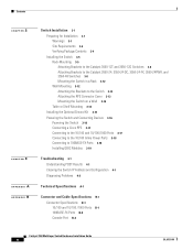
...01 Preface vii Audience vii Purpose vii Conventions vii Related Publications xiii Obtaining Documentation xiv Cisco.com xiv Documentation CD-ROM xiv Ordering Documentation xv Documentation Feedback xv Obtaining Technical Assistance xv Cisco TAC Website xv Opening a TAC Case xvi TAC Case Priority Definitions xvi Obtaining Additional... LED 2-6 RPS LED 2-7 Port LEDs and Modes 2-7 Rear-Panel Description 2-10 AC Power Connector 2-11 Cisco RPS Connector 2-11 Console Port 2-11 Management Options 2-11 Network Configurations 2-12 CONTENTS Catalyst 3550 Multilayer Switch Hardware Installation Guide iii
...01 Preface vii Audience vii Purpose vii Conventions vii Related Publications xiii Obtaining Documentation xiv Cisco.com xiv Documentation CD-ROM xiv Ordering Documentation xv Documentation Feedback xv Obtaining Technical Assistance xv Cisco TAC Website xv Opening a TAC Case xvi TAC Case Priority Definitions xvi Obtaining Additional... LED 2-6 RPS LED 2-7 Port LEDs and Modes 2-7 Rear-Panel Description 2-10 AC Power Connector 2-11 Cisco RPS Connector 2-11 Console Port 2-11 Management Options 2-11 Network Configurations 2-12 CONTENTS Catalyst 3550 Multilayer Switch Hardware Installation Guide iii
Hardware Installation Guide
Page 4
... for Installation 3-1 Warnings 3-1 Site Requirements 3-4 Verifying Package Contents 3-4 Installing the Switch 3-5 Rack-Mounting 3-5 Attaching Brackets to the Catalyst 3550-12T and 3550-12G Switches 3-6 Attaching Brackets to the Catalyst 3550-24, 3550-24-DC, 3550-24-FX, 3550-24PWR, and 3550-48 Switches 3-8 Mounting the Switch in a Rack 3-12 Wall Mounting 3-12 Attaching the Brackets to the Switch 3-13 Attaching the RPS Connector Cover 3-13 Mounting the...
... for Installation 3-1 Warnings 3-1 Site Requirements 3-4 Verifying Package Contents 3-4 Installing the Switch 3-5 Rack-Mounting 3-5 Attaching Brackets to the Catalyst 3550-12T and 3550-12G Switches 3-6 Attaching Brackets to the Catalyst 3550-24, 3550-24-DC, 3550-24-FX, 3550-24PWR, and 3550-48 Switches 3-8 Mounting the Switch in a Rack 3-12 Wall Mounting 3-12 Attaching the Brackets to the Switch 3-13 Attaching the RPS Connector Cover 3-13 Mounting the...

Hardware Installation Guide
Page 7
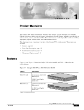
... physical and performance characteristics of multilayer switches. For more information, see the Cisco IOS documentation set on Cisco.com. For information about the standard Cisco IOS Release 12.2 commands, see the Catalyst 3550 Multilayer Switch Software Configuration Guide, the Catalyst 3550 Multilayer Switch Command Reference, the Catalyst 3550 Multilayer Switch System Message Guide, and the release notes on Cisco.com. We assume that you might...
... physical and performance characteristics of multilayer switches. For more information, see the Cisco IOS documentation set on Cisco.com. For information about the standard Cisco IOS Release 12.2 commands, see the Catalyst 3550 Multilayer Switch Software Configuration Guide, the Catalyst 3550 Multilayer Switch Command Reference, the Catalyst 3550 Multilayer Switch System Message Guide, and the release notes on Cisco.com. We assume that you might...
Hardware Installation Guide
Page 19
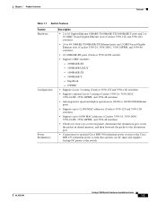
Figure 1-1 Catalyst 3550-12T and 3550-12G Switch Models Switch Description WS-C3550-12T 10 autosensing 10/100/1000 Ethernet ports 2 GBIC1-based Gigabit module slots SYSTEM RPS MODE STATUS UTIL DUPLX SPEED 1 2 3 4 5 6 7 8 9 10 Catalyst 3550 1 2 WS-C3550-12G 2 autosensing 10/100/1000 Ethernet ports 10 GBIC-based Gigabit module slots SYSTEM RPS MODE STATUS UTIL DUPLX SPEED 1 3 2 5 Catalyst 3550 4 7 6 9 11 8 12 10...
Figure 1-1 Catalyst 3550-12T and 3550-12G Switch Models Switch Description WS-C3550-12T 10 autosensing 10/100/1000 Ethernet ports 2 GBIC1-based Gigabit module slots SYSTEM RPS MODE STATUS UTIL DUPLX SPEED 1 2 3 4 5 6 7 8 9 10 Catalyst 3550 1 2 WS-C3550-12G 2 autosensing 10/100/1000 Ethernet ports 10 GBIC-based Gigabit module slots SYSTEM RPS MODE STATUS UTIL DUPLX SPEED 1 3 2 5 Catalyst 3550 4 7 6 9 11 8 12 10...
Hardware Installation Guide
Page 21
... to 12,000 MAC addresses (Catalyst 3550-12T and 3550-12G switches) • Supports up to 8,000 MAC addresses (Catalyst 3550-24, 3550-24DC, 3550-24-FX, 3550-24PWR, and 3550-48 switches) • Checks for errors on a received packet, determines the destination port, stores the packet in shared memory, and then forwards the packet to the destination port • Connection for optional Cisco...
... to 12,000 MAC addresses (Catalyst 3550-12T and 3550-12G switches) • Supports up to 8,000 MAC addresses (Catalyst 3550-24, 3550-24DC, 3550-24-FX, 3550-24PWR, and 3550-48 switches) • Checks for errors on a received packet, determines the destination port, stores the packet in shared memory, and then forwards the packet to the destination port • Connection for optional Cisco...
Hardware Installation Guide
Page 22
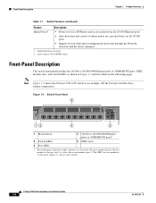
... 1 2 3 4 5 6 7 8 9 10 Catalyst 3550 SERIES 1 2 101603 12 4 5 1 Mode button 2 Switch LEDs 3 Port LEDs 4 10/100 or 10/100/1000 Ethernet ports or 100BASE-FX ports1 5 GBIC slots 1. Note Figure 1-3 shows the Catalyst 3550-12T switch as shown in pairs, the first member of inline power on a per-port basis on all 10/100 ports • Support for Cisco IP Phones...
... 1 2 3 4 5 6 7 8 9 10 Catalyst 3550 SERIES 1 2 101603 12 4 5 1 Mode button 2 Switch LEDs 3 Port LEDs 4 10/100 or 10/100/1000 Ethernet ports or 100BASE-FX ports1 5 GBIC slots 1. Note Figure 1-3 shows the Catalyst 3550-12T switch as shown in pairs, the first member of inline power on a per-port basis on all 10/100 ports • Support for Cisco IP Phones...

Hardware Installation Guide
Page 27
... Utilization for the Catalyst 3550-12T 74026 SYSTEM RPS STATUS UTIL DUPLX SPEED MODE 1 2 3 4 5 6 7 8 9 10 < 25% + 25% - 49% + 50% + Catalyst 3550 SERIES 1 2 Figure 1-5 shows the bandwidth utilization percentages displayed by the LEDs on the Catalyst 3550-12G switch. Figure 1-4 Bandwidth Utilization for the Catalyst 3550-24 and 3550-24-DC 74023 MODE SYSTEM RPS STATUS UTIL DUPLX SPEED 12 1X 34 56...
... Utilization for the Catalyst 3550-12T 74026 SYSTEM RPS STATUS UTIL DUPLX SPEED MODE 1 2 3 4 5 6 7 8 9 10 < 25% + 25% - 49% + 50% + Catalyst 3550 SERIES 1 2 Figure 1-5 shows the bandwidth utilization percentages displayed by the LEDs on the Catalyst 3550-12G switch. Figure 1-4 Bandwidth Utilization for the Catalyst 3550-24 and 3550-24-DC 74023 MODE SYSTEM RPS STATUS UTIL DUPLX SPEED 12 1X 34 56...

Hardware Installation Guide
Page 28
...-Panel Description Other than the Catalyst 3550-24-DC switch, the switch rear panels have similar components. All the Catalyst switches have an AC power connector, an RPS connector, and an RJ-45 console port, which are shown in Figure 1-9 and described in the DC power connector. Note Figure 1-9 shows the Catalyst 3550-12T switch as the terminal block header...
...-Panel Description Other than the Catalyst 3550-24-DC switch, the switch rear panels have similar components. All the Catalyst switches have an AC power connector, an RPS connector, and an RJ-45 console port, which are shown in Figure 1-9 and described in the DC power connector. Note Figure 1-9 shows the Catalyst 3550-12T switch as the terminal block header...
Hardware Installation Guide
Page 29
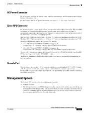
...Catalyst 3550 switches offer several management options: • Network Assistant • The Network Assistant is an autoranging unit that adapter from Cisco. For more information. The Cisco RPS 300 has two output levels: -48 V and 12...Cisco RPS models support the Catalyst 3550 switches: • Cisco RPS 300 (model PWR300-AC-RPS-N1) supports the Catalyst 3550-12T, 3550-12G, 3550-24, 3550-FX, and 3550-48 switches. • Cisco RPS 675 (model PWR675-AC-RPS-N1) supports the Catalyst 3550-12T, 3550-12G, 3550-24, 3550-FX, 3550-24PWR, and 3550-48 switches. OL-6155-01 Catalyst 3550 Switch...
...Catalyst 3550 switches offer several management options: • Network Assistant • The Network Assistant is an autoranging unit that adapter from Cisco. For more information. The Cisco RPS 300 has two output levels: -48 V and 12...Cisco RPS models support the Catalyst 3550 switches: • Cisco RPS 300 (model PWR300-AC-RPS-N1) supports the Catalyst 3550-12T, 3550-12G, 3550-24, 3550-FX, and 3550-48 switches. • Cisco RPS 675 (model PWR675-AC-RPS-N1) supports the Catalyst 3550-12T, 3550-12G, 3550-24, 3550-FX, 3550-24PWR, and 3550-48 switches. OL-6155-01 Catalyst 3550 Switch...

Hardware Installation Guide
Page 30
... the CLI either by connecting your network through a web browser. Cisco provides a collection of pretested, Cisco-recommended baseline SmartPort macros for network configuration concepts and examples. 1-12 Catalyst 3550 Switch Hardware Installation Guide OL-6155-01 Use the device manager to view switch status and performance information. The switch supports a comprehensive set configuration parameters and to perform basic...
... the CLI either by connecting your network through a web browser. Cisco provides a collection of pretested, Cisco-recommended baseline SmartPort macros for network configuration concepts and examples. 1-12 Catalyst 3550 Switch Hardware Installation Guide OL-6155-01 Use the device manager to view switch status and performance information. The switch supports a comprehensive set configuration parameters and to perform basic...
Hardware Installation Guide
Page 35
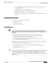
... brackets and hardware from the bottom to the Catalyst 3550-24, 3550-24-DC, 3550-24-FX, 3550-24PWR, and 3550-48 Switches, page 2-8 • Mounting the Switch in a Rack, page 2-12 Note Installing the switch in a 24-inch rack requires an optional bracket...Catalyst 3550-12T and 3550-12G switches, order part number RCKMNT-3550-1.5RU=. OL-6155-01 Catalyst 3550 Switch Hardware Installation Guide 2-5 One cable guide and one of the rack. • If the rack is the only unit in the rack. • When mounting this unit in a partially filled rack, load the rack from Cisco. Chapter 2 Switch...
... brackets and hardware from the bottom to the Catalyst 3550-24, 3550-24-DC, 3550-24-FX, 3550-24PWR, and 3550-48 Switches, page 2-8 • Mounting the Switch in a Rack, page 2-12 Note Installing the switch in a 24-inch rack requires an optional bracket...Catalyst 3550-12T and 3550-12G switches, order part number RCKMNT-3550-1.5RU=. OL-6155-01 Catalyst 3550 Switch Hardware Installation Guide 2-5 One cable guide and one of the rack. • If the rack is the only unit in the rack. • When mounting this unit in a partially filled rack, load the rack from Cisco. Chapter 2 Switch...

Hardware Installation Guide
Page 38
..." Configuration Phillips flat-head screws Figure 2-6 Attaching Brackets for 24-Inch Telco Racks 74035 2 3 4 5 6 Catalyst 3550 SERIES 7 8 9 10 11 12 24" Configuration Phillips flat-head screws 74040 Attaching Brackets to the Catalyst 3550-24, 3550-24-DC, 3550-24-FX, 3550-24PWR, and 3550-48 Switches The bracket orientation and the brackets that are on whether you use depend on...
..." Configuration Phillips flat-head screws Figure 2-6 Attaching Brackets for 24-Inch Telco Racks 74035 2 3 4 5 6 Catalyst 3550 SERIES 7 8 9 10 11 12 24" Configuration Phillips flat-head screws 74040 Attaching Brackets to the Catalyst 3550-24, 3550-24-DC, 3550-24-FX, 3550-24PWR, and 3550-48 Switches The bracket orientation and the brackets that are on whether you use depend on...

Hardware Installation Guide
Page 39
Chapter 2 Switch Installation Figure 2-7 Attaching Brackets for 19-Inch Racks, Front Panel Forward Installing the Switch 60138 Phillips flat-head screws SYSTEM RPS MODE STATUS UTIL DUPLX SPEED 1 1X 23 45 67 8 9 10 11 12 11X 2X 12X 19" Configuration Figure 2-8 Attaching Brackets for 24-Inch Racks, Front Panel Forward Phillips flat-head screws SYSTEM RPS MODE STATUS UTIL DUPLX SPEED 1 1X 23 45 67 8 9 10 11 12 11X 2X 12X 24" Configuration 60139 OL-6155-01 Catalyst 3550 Switch Hardware Installation Guide 2-9
Chapter 2 Switch Installation Figure 2-7 Attaching Brackets for 19-Inch Racks, Front Panel Forward Installing the Switch 60138 Phillips flat-head screws SYSTEM RPS MODE STATUS UTIL DUPLX SPEED 1 1X 23 45 67 8 9 10 11 12 11X 2X 12X 19" Configuration Figure 2-8 Attaching Brackets for 24-Inch Racks, Front Panel Forward Phillips flat-head screws SYSTEM RPS MODE STATUS UTIL DUPLX SPEED 1 1X 23 45 67 8 9 10 11 12 11X 2X 12X 24" Configuration 60139 OL-6155-01 Catalyst 3550 Switch Hardware Installation Guide 2-9

Hardware Installation Guide
Page 41
Chapter 2 Switch Installation Figure 2-11 Attaching Brackets for 19-Inch Telco Racks 1 Catalyst 3550 SERIES 2 19" Configuration Phillips flat-head screws Figure 2-12 Attaching Brackets for 24-Inch Telco Racks 1 Catalyst 3550 SERIES 2 24" Configuration Phillips flat-head screws 74036 Installing the Switch 74037 OL-6155-01 Catalyst 3550 Switch Hardware Installation Guide 2-11
Chapter 2 Switch Installation Figure 2-11 Attaching Brackets for 19-Inch Telco Racks 1 Catalyst 3550 SERIES 2 19" Configuration Phillips flat-head screws Figure 2-12 Attaching Brackets for 24-Inch Telco Racks 1 Catalyst 3550 SERIES 2 24" Configuration Phillips flat-head screws 74036 Installing the Switch 74037 OL-6155-01 Catalyst 3550 Switch Hardware Installation Guide 2-11

Hardware Installation Guide
Page 42
... a wall, follow the instructions in these procedures: • Attaching the Brackets to the rack, as shown in this section show the Catalyst 3550-12T switch as shown in the rack. Installing the Switch Chapter 2 Switch Installation Mounting the Switch in a Rack After the brackets are wall-mounted following the same procedures. 2-12 Catalyst 3550 Switch Hardware Installation Guide OL-6155-01
... a wall, follow the instructions in these procedures: • Attaching the Brackets to the rack, as shown in this section show the Catalyst 3550-12T switch as shown in the rack. Installing the Switch Chapter 2 Switch Installation Mounting the Switch in a Rack After the brackets are wall-mounted following the same procedures. 2-12 Catalyst 3550 Switch Hardware Installation Guide OL-6155-01

Hardware Installation Guide
Page 44
... with the rubber feet in Figure 2-17. Statement 266 Figure 2-17 Mounting the Switch on a Wall Catalyst 3550 11 12 1 2 3 4 5 6 7 8 9 10 MODE SPEEDDUPLX USTITLATUS RSPYSSTEM User-supplied screws 60967 User-supplied screws Table or Shelf Mounting Follow these steps to install the switch on a table or shelf: Step 1 Step 2 Locate the adhesive strip with the...
... with the rubber feet in Figure 2-17. Statement 266 Figure 2-17 Mounting the Switch on a Wall Catalyst 3550 11 12 1 2 3 4 5 6 7 8 9 10 MODE SPEEDDUPLX USTITLATUS RSPYSSTEM User-supplied screws 60967 User-supplied screws Table or Shelf Mounting Follow these steps to install the switch on a table or shelf: Step 1 Step 2 Locate the adhesive strip with the...
Hardware Installation Guide
Page 45
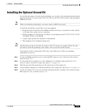
...Cisco. Make sure to follow these tools and equipment: • Ratcheting torque screwdriver with a Phillips head that require a two-hole lug for stripping 6-gauge wires Note The illustrations in this section show the Catalyst 3550-12T switch as shown in .) of the 6-gauge wire. OL-6155-01 Catalyst 3550 Switch... ounce-force inches (ozf-in Figure 2-16. To ground the switch to earth ground, follow any grounding requirements at your ground wire is insulated, use a wire stripping tool to strip the 6-gauge ground wire to 0.5 inch (12.7 mm) ± 0.02 inch (0.5 mm). (See Figure ...
...Cisco. Make sure to follow these tools and equipment: • Ratcheting torque screwdriver with a Phillips head that require a two-hole lug for stripping 6-gauge wires Note The illustrations in this section show the Catalyst 3550-12T switch as shown in .) of the 6-gauge wire. OL-6155-01 Catalyst 3550 Switch... ounce-force inches (ozf-in Figure 2-16. To ground the switch to earth ground, follow any grounding requirements at your ground wire is insulated, use a wire stripping tool to strip the 6-gauge ground wire to 0.5 inch (12.7 mm) ± 0.02 inch (0.5 mm). (See Figure ...
Hardware Installation Guide
Page 56
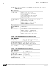
...) 1.6 A/0.9 A, 50 to 60 Hz Catalyst 3550-12T and 3550-12G: +12 V @13 A Catalyst 3550-24: +12 V @8.5 A Catalyst 3550-24-FX: +12 V @8.5 A Catalyst 3550-48: +12 V @13 A +12 V @25 A Catalyst 3550-12T and 3550-12G: 190 W, 650 Btus per hour Catalyst 3550-24: 65 W, 222 Btus per hour Catalyst 3550-24-FX: 85 W, 290 Btus per hour Catalyst 3550-48: 110 W, 375 Btus per hour Table A-3 Power Requirements for the Catalyst 3550-24PWR Switch Power Requirements AC input voltage...
...) 1.6 A/0.9 A, 50 to 60 Hz Catalyst 3550-12T and 3550-12G: +12 V @13 A Catalyst 3550-24: +12 V @8.5 A Catalyst 3550-24-FX: +12 V @8.5 A Catalyst 3550-48: +12 V @13 A +12 V @25 A Catalyst 3550-12T and 3550-12G: 190 W, 650 Btus per hour Catalyst 3550-24: 65 W, 222 Btus per hour Catalyst 3550-24-FX: 85 W, 290 Btus per hour Catalyst 3550-48: 110 W, 375 Btus per hour Table A-3 Power Requirements for the Catalyst 3550-24PWR Switch Power Requirements AC input voltage...

Hardware Installation Guide
Page 66
... and remove the ground lug and the two number-10-32 ground-lug screws from the rear panel of the switch. (See Figure C-3 for stripping 6- Statement 42 To ground the switch to 0.5 inch (12.7 mm) ± 0.02 inch (0.5 mm), as shown in . (0.5 mm) 60528 Insulation Wire lead Step 3... torque screwdriver with a Phillips head. If your site. Statement 39 Caution To make the ground connection first and disconnect it last. Catalyst 3550 Multilayer Switch Hardware Installation Guide C-2 OL-6155-01 Set the screws and the ground lug aside. and 18-gauge wires Grounding the...
... and remove the ground lug and the two number-10-32 ground-lug screws from the rear panel of the switch. (See Figure C-3 for stripping 6- Statement 42 To ground the switch to 0.5 inch (12.7 mm) ± 0.02 inch (0.5 mm), as shown in . (0.5 mm) 60528 Insulation Wire lead Step 3... torque screwdriver with a Phillips head. If your site. Statement 39 Caution To make the ground connection first and disconnect it last. Catalyst 3550 Multilayer Switch Hardware Installation Guide C-2 OL-6155-01 Set the screws and the ground lug aside. and 18-gauge wires Grounding the...

Hardware Installation Guide
Page 73
...Setup mode, open a Telnet session to the "Accessing the CLI Through the Console Port" section on the switch and using Express Setup. OL-6155-01 Catalyst 3550 Multilayer Switch Hardware Installation Guide D-1 These sections describe each method: • Accessing the CLI Through Express Setup, page ... then configure the switch by using the write memory privileged EXEC command. Note For switches running Cisco IOS Release 12.1(14)EA1 or later. After the switch is supported on switches running releases earlier than Cisco IOS Release 12.1(14)EA1, go to the switch by entering the ...
...Setup mode, open a Telnet session to the "Accessing the CLI Through the Console Port" section on the switch and using Express Setup. OL-6155-01 Catalyst 3550 Multilayer Switch Hardware Installation Guide D-1 These sections describe each method: • Accessing the CLI Through Express Setup, page ... then configure the switch by using the write memory privileged EXEC command. Note For switches running Cisco IOS Release 12.1(14)EA1 or later. After the switch is supported on switches running releases earlier than Cisco IOS Release 12.1(14)EA1, go to the switch by entering the ...


