Hardware Installation Guide
Page 4
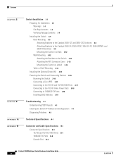
... Devices 3-16 Powering the Switch 3-16 Connecting a Cisco RPS 3-17 Connecting to the 10/100 and 10/100/1000 Ports 3-17 Connecting to the 10/100 Inline Power Ports 3-18 Connecting to 100BASE-FX Ports 3-18 Installing GBIC Modules 3-19 Troubleshooting 4-1 Understanding POST Results 4-1 Clearing the Switch IP Address and Configuration 4-1 Diagnosing Problems 4-2 Technical Specifications A-1 Connector and Cable Specifications B-1 Connector Specifications B-1 10/100 and 10/100 /1000 Ports B-1 100BASE-FX Ports B-2 Console Port B-2 Catalyst 3550 Multilayer Switch Hardware Installation Guide iv OL...
... Devices 3-16 Powering the Switch 3-16 Connecting a Cisco RPS 3-17 Connecting to the 10/100 and 10/100/1000 Ports 3-17 Connecting to the 10/100 Inline Power Ports 3-18 Connecting to 100BASE-FX Ports 3-18 Installing GBIC Modules 3-19 Troubleshooting 4-1 Understanding POST Results 4-1 Clearing the Switch IP Address and Configuration 4-1 Diagnosing Problems 4-2 Technical Specifications A-1 Connector and Cable Specifications B-1 Connector Specifications B-1 10/100 and 10/100 /1000 Ports B-1 100BASE-FX Ports B-2 Console Port B-2 Catalyst 3550 Multilayer Switch Hardware Installation Guide iv OL...
Hardware Installation Guide
Page 21
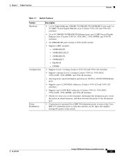
... MAC addresses (Catalyst 3550-24, 3550-24DC, 3550-24-FX, 3550-24PWR, and 3550-48 switches) • Checks for errors on a received packet, determines the destination port, stores the packet in shared memory, and then forwards the packet to the destination port • Connection for optional Cisco RPS 300 redundant power system or the Cisco RPS 675 redundant power system that operates on AC input and supplies backup DC power to the switch OL-6155-01 Catalyst 3550 Switch Hardware Installation Guide...
... MAC addresses (Catalyst 3550-24, 3550-24DC, 3550-24-FX, 3550-24PWR, and 3550-48 switches) • Checks for errors on a received packet, determines the destination port, stores the packet in shared memory, and then forwards the packet to the destination port • Connection for optional Cisco RPS 300 redundant power system or the Cisco RPS 675 redundant power system that operates on AC input and supplies backup DC power to the switch OL-6155-01 Catalyst 3550 Switch Hardware Installation Guide...
Hardware Installation Guide
Page 22
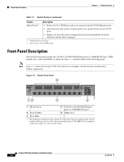
... RPS STATUS UTIL DUPLX SPEED MODE 1 2 3 4 5 6 7 8 9 10 Catalyst 3550 SERIES 1 2 101603 12 4 5 1 Mode button 2 Switch LEDs 3 Port LEDs 4 10/100 or 10/100/1000 Ethernet ports or 100BASE-FX ports1 5 GBIC slots 1. For ports grouped in Figure 1-3 and described on the following pages. The GBIC slots are numbered 1 (left . Front-Panel Description Chapter 1 Product Overview Table 1-1 Switch Features (continued) Feature Inline Power2 Description • Power for Cisco IP Phones and access...
... RPS STATUS UTIL DUPLX SPEED MODE 1 2 3 4 5 6 7 8 9 10 Catalyst 3550 SERIES 1 2 101603 12 4 5 1 Mode button 2 Switch LEDs 3 Port LEDs 4 10/100 or 10/100/1000 Ethernet ports or 100BASE-FX ports1 5 GBIC slots 1. For ports grouped in Figure 1-3 and described on the following pages. The GBIC slots are numbered 1 (left . Front-Panel Description Chapter 1 Product Overview Table 1-1 Switch Features (continued) Feature Inline Power2 Description • Power for Cisco IP Phones and access...

Hardware Installation Guide
Page 23
... power on a port, the port does not provide power even if a Cisco IP phone or an access point is not supported. The Auto setting is connected. You can configure interface speed on page B-2. or half-duplex mode. You can connect a 100BASE-FX port to full, half, or autonegotiate. On Fast Ethernet ports, you can either receive or send traffic. At this setting, the port senses the speed and duplex settings of the MT-RJ fiber-optic patch cables listed...
... power on a port, the port does not provide power even if a Cisco IP phone or an access point is not supported. The Auto setting is connected. You can configure interface speed on page B-2. or half-duplex mode. You can connect a 100BASE-FX port to full, half, or autonegotiate. On Fast Ethernet ports, you can either receive or send traffic. At this setting, the port senses the speed and duplex settings of the MT-RJ fiber-optic patch cables listed...

Hardware Installation Guide
Page 24
The GigaStack GBIC supports one of the port modes. Table 1-2 System LED Color Off System Status System is not powered on the device manager and through the Network Assistant. Catalyst 3550 Switch Hardware Installation Guide 1-6 OL-6155-01 LEDs System LED You can configure speed to not negotiate (nonegotiate) if connected to a device that contains the module serial number, the vendor name and vendor ID, a unique security code, and cyclic redundancy check (CRC). Table 1-2 lists the LED colors and...
The GigaStack GBIC supports one of the port modes. Table 1-2 System LED Color Off System Status System is not powered on the device manager and through the Network Assistant. Catalyst 3550 Switch Hardware Installation Guide 1-6 OL-6155-01 LEDs System LED You can configure speed to not negotiate (nonegotiate) if connected to a device that contains the module serial number, the vendor name and vendor ID, a unique security code, and cyclic redundancy check (CRC). Table 1-2 lists the LED colors and...

Hardware Installation Guide
Page 25
... Catalyst 3550 Switch Hardware Installation Guide 1-7 Table 1-3 lists the LED colors and their associated port modes and meanings. RPS is off or not properly connected. If it is highlighted. To select or change a mode, press the Mode button (or Mode label on the RPS, and the LED should turn green. Table 1-5 explains how to this device). Table 1-3 RPS LED Color Off Solid green Blinking green Solid amber Blinking amber RPS Status RPS is connected and ready to clear the switch IP address and all switch settings. Port LEDs...
... Catalyst 3550 Switch Hardware Installation Guide 1-7 Table 1-3 lists the LED colors and their associated port modes and meanings. RPS is off or not properly connected. If it is highlighted. To select or change a mode, press the Mode button (or Mode label on the RPS, and the LED should turn green. Table 1-5 explains how to this device). Table 1-3 RPS LED Color Off Solid green Blinking green Solid amber Blinking amber RPS Status RPS is connected and ready to clear the switch IP address and all switch settings. Port LEDs...
Hardware Installation Guide
Page 29
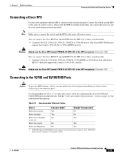
... power of network traffic. The Cisco RPS can connect the switch to a PC by using the console port and the supplied RJ-45-to the failed device, preventing loss of 300 W. The Cisco RPS 300 has two output levels: -48 V and 12 V with Cisco Network Assistant guide and the Network Assistant online help. These Cisco RPS models support the Catalyst 3550 switches: • Cisco RPS 300 (model PWR300-AC-RPS-N1) supports the Catalyst 3550-12T, 3550-12G, 3550-24, 3550...
... power of network traffic. The Cisco RPS can connect the switch to a PC by using the console port and the supplied RJ-45-to the failed device, preventing loss of 300 W. The Cisco RPS 300 has two output levels: -48 V and 12 V with Cisco Network Assistant guide and the Network Assistant online help. These Cisco RPS models support the Catalyst 3550 switches: • Cisco RPS 300 (model PWR300-AC-RPS-N1) supports the Catalyst 3550-12T, 3550-12G, 3550-24, 3550...

Hardware Installation Guide
Page 30
... to the switch console port or by generating switch-specific configuration changes, sending them to the switch, executing the configuration change, and logging the results. Cisco provides a collection of pretested, Cisco-recommended baseline SmartPort macros for network configuration concepts and examples. 1-12 Catalyst 3550 Switch Hardware Installation Guide OL-6155-01 You can access the device manager from a remote management station. The device manager is enhanced to perform basic switch configuration and monitoring. Use the device manager to support desktop-switching...
... to the switch console port or by generating switch-specific configuration changes, sending them to the switch, executing the configuration change, and logging the results. Cisco provides a collection of pretested, Cisco-recommended baseline SmartPort macros for network configuration concepts and examples. 1-12 Catalyst 3550 Switch Hardware Installation Guide OL-6155-01 You can access the device manager from a remote management station. The device manager is enhanced to perform basic switch configuration and monitoring. Use the device manager to support desktop-switching...
Hardware Installation Guide
Page 35
... bracket kit not included with stabilizing devices, install the stabilizers before mounting or servicing the unit in a rack, you must take special precautions to one black Phillips machine screw for wall mounting) - Four Phillips truss-head screws (for attaching the RPS cover) - For the Catalyst 3550-12T and 3550-12G switches, order part number RCKMNT-3550-1.5RU=. Two Phillips pan-head screws (for...
... bracket kit not included with stabilizing devices, install the stabilizers before mounting or servicing the unit in a rack, you must take special precautions to one black Phillips machine screw for wall mounting) - Four Phillips truss-head screws (for attaching the RPS cover) - For the Catalyst 3550-12T and 3550-12G switches, order part number RCKMNT-3550-1.5RU=. Two Phillips pan-head screws (for...

Hardware Installation Guide
Page 42
All the Catalyst 3550 switches are attached to the switch, use the four supplied number-12 Phillips machine screws to securely attach the brackets to the rack, as shown in Figure 2-13. Use the supplied black screw, as an example. Figure 2-14 Attaching the Cable Guide on the Switch 74034 SYSTEM RPS MODE STATUS UTIL DUPLX SPEED 1 2 3 4 5 6 Catalyst 3550 SERIES 7 8 9 10 1 2 Cable guide screw Wall Mounting To install the switch on a wall, follow the instructions in these...
All the Catalyst 3550 switches are attached to the switch, use the four supplied number-12 Phillips machine screws to securely attach the brackets to the rack, as shown in Figure 2-13. Use the supplied black screw, as an example. Figure 2-14 Attaching the Cable Guide on the Switch 74034 SYSTEM RPS MODE STATUS UTIL DUPLX SPEED 1 2 3 4 5 6 Catalyst 3550 SERIES 7 8 9 10 1 2 Cable guide screw Wall Mounting To install the switch on a wall, follow the instructions in these...
Hardware Installation Guide
Page 45
... wire to install the ground lug on page C-3.) Use the two number-10-32 screws to attach the ground lug and wire assembly to the switch rear panel RPS connector cover, as shown in this section show the Catalyst 3550-12T switch as shown in Figure 2-16. For the Catalyst 3550-12G, 3550-24, and 3550-24-FX switches, order part number NEBS-LUG-3550=. Make...
... wire to install the ground lug on page C-3.) Use the two number-10-32 screws to attach the ground lug and wire assembly to the switch rear panel RPS connector cover, as shown in this section show the Catalyst 3550-12T switch as shown in Figure 2-16. For the Catalyst 3550-12G, 3550-24, and 3550-24-FX switches, order part number NEBS-LUG-3550=. Make...
Hardware Installation Guide
Page 47
... No Switch to hub Yes No Switch to computer No Yes or server Switch to router No Yes Switch to IP phone No Yes 1. 100BASE-TX and 1000BASE-T traffic requires twisted four-pair, Category 5 cable. 10BASE-T traffic can connect the Cisco RPS 300 (model PWR300-AC-RPS-N1) to these switch models. • Catalyst 3550-12T, 3550-12G, 3550-24, 3550-FX, 3550-24PWR, or 3550-48 switch. (The Cisco RPS 675 does not support the Catalyst 3550...
... No Switch to hub Yes No Switch to computer No Yes or server Switch to router No Yes Switch to IP phone No Yes 1. 100BASE-TX and 1000BASE-T traffic requires twisted four-pair, Category 5 cable. 10BASE-T traffic can connect the Cisco RPS 300 (model PWR300-AC-RPS-N1) to these switch models. • Catalyst 3550-12T, 3550-12G, 3550-24, 3550-FX, 3550-24PWR, or 3550-48 switch. (The Cisco RPS 675 does not support the Catalyst 3550...

Hardware Installation Guide
Page 48
... its backup. The power source to that came with the switch. and half-duplex mode. Insert the cable in a restricted access location and users and service people who are authorized to that present a shock hazard can connect the Cisco IP Phone or Cisco Aironet Access Point to a Catalyst 3550-24PWR 10/100 port and to the Catalyst 3550-24PWR switch. During the power transfer, the device might have established a link. 2-18 Catalyst 3550 Switch Hardware Installation Guide...
... its backup. The power source to that came with the switch. and half-duplex mode. Insert the cable in a restricted access location and users and service people who are authorized to that present a shock hazard can connect the Cisco IP Phone or Cisco Aironet Access Point to a Catalyst 3550-24PWR 10/100 port and to the Catalyst 3550-24PWR switch. During the power transfer, the device might have established a link. 2-18 Catalyst 3550 Switch Hardware Installation Guide...

Hardware Installation Guide
Page 51
Clearing the Switch IP Address and Configuration If you have configured a new switch with the test is configured on the switch. When POST completes, the port LEDs return to enter Express Setup mode, you want to view the POST results. POST failures are trying to the status mode display, and the system LED is green. OL-6155-01 Catalyst 3550 Switch Hardware Installation Guide 3-1 If POST fails, the SYST LED turns amber. To clear the IP address and the switch configuration information...
Clearing the Switch IP Address and Configuration If you have configured a new switch with the test is configured on the switch. When POST completes, the port LEDs return to enter Express Setup mode, you want to view the POST results. POST failures are trying to the status mode display, and the system LED is green. OL-6155-01 Catalyst 3550 Switch Hardware Installation Guide 3-1 If POST fails, the SYST LED turns amber. To clear the IP address and the switch configuration information...
Hardware Installation Guide
Page 52
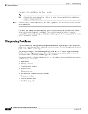
... problems • Network interface cards • Troubleshooting tools Catalyst 3550 Switch Hardware Installation Guide 3-2 OL-6155-01 Note If the switch is not configured, the LEDs are all green. They show POST failures, port-connectivity problems, and overall switch performance. You can omit Step 2 and run Express Setup to configure the switch. See the software configuration guide and the switch command reference guide on Cisco.com or the documentation that came with the CLI-Based Setup Program." Diagnosing Problems Chapter 3 Troubleshooting The switch LEDs begin blinking...
... problems • Network interface cards • Troubleshooting tools Catalyst 3550 Switch Hardware Installation Guide 3-2 OL-6155-01 Note If the switch is not configured, the LEDs are all green. They show POST failures, port-connectivity problems, and overall switch performance. You can omit Step 2 and run Express Setup to configure the switch. See the software configuration guide and the switch command reference guide on Cisco.com or the documentation that came with the CLI-Based Setup Program." Diagnosing Problems Chapter 3 Troubleshooting The switch LEDs begin blinking...

Hardware Installation Guide
Page 54
... the hardware. Diagnosing Problems Chapter 3 Troubleshooting Table 3-1 Common Problems and Solutions (continued) Problem No connectivity Poor performance or excessive errors Solution • Verify that the devices at both ends of all ports or a specified port. • The cabling distance might be a speed and duplex autonegotiation mismatch. Wait 30 seconds for the port LED to turn green. • For 1000BASE-T connections, make sure to use the show controllers ethernet-controller privileged EXEC command to...
... the hardware. Diagnosing Problems Chapter 3 Troubleshooting Table 3-1 Common Problems and Solutions (continued) Problem No connectivity Poor performance or excessive errors Solution • Verify that the devices at both ends of all ports or a specified port. • The cabling distance might be a speed and duplex autonegotiation mismatch. Wait 30 seconds for the port LED to turn green. • For 1000BASE-T connections, make sure to use the show controllers ethernet-controller privileged EXEC command to...
Hardware Installation Guide
Page 65
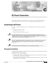
... Warning Ethernet cables must be accessed only through the use of a special tool, lock and key, or other means of pressure • Panduit crimping tool with a Phillips head that exerts up to remove or replace any components. Statement 171 Preparing for installation in a central office environment. Connecting to DC Power To connect the Catalyst 3550-24-DC switch to the Catalyst 3550-24-DC switch. C A P P E N D I X DC Power Connections This...
... Warning Ethernet cables must be accessed only through the use of a special tool, lock and key, or other means of pressure • Panduit crimping tool with a Phillips head that exerts up to remove or replace any components. Statement 171 Preparing for installation in a central office environment. Connecting to DC Power To connect the Catalyst 3550-24-DC switch to the Catalyst 3550-24-DC switch. C A P P E N D I X DC Power Connections This...

Hardware Installation Guide
Page 73
...EXEC command. D A P P E N D I X Configuring the Switch with the CLI-Based Setup Program This appendix provides a command-line interface (CLI)-based setup procedure for the switch, save it to Flash memory by using Express Setup. OL-6155-01 Catalyst 3550 Multilayer Switch Hardware Installation Guide D-1 These sections describe each method: • Accessing the CLI Through Express Setup, page D-1 • Accessing the CLI Through the Console Port, page D-2 Accessing the CLI Through Express Setup Express Setup is in Express Setup mode, open a Telnet session to a power source, review...
...EXEC command. D A P P E N D I X Configuring the Switch with the CLI-Based Setup Program This appendix provides a command-line interface (CLI)-based setup procedure for the switch, save it to Flash memory by using Express Setup. OL-6155-01 Catalyst 3550 Multilayer Switch Hardware Installation Guide D-1 These sections describe each method: • Accessing the CLI Through Express Setup, page D-1 • Accessing the CLI Through the Console Port, page D-2 Accessing the CLI Through Express Setup Express Setup is in Express Setup mode, open a Telnet session to a power source, review...

Hardware Installation Guide
Page 76
... a course of the supplied AC power cord to the power connector on the switch rear panel. If you started the terminal emulation program before you complete the setup program: • Switch IP address • Subnet mask (IP netmask) • Default gateway (router) • Enable secret password • Enable password • Telnet password Catalyst 3550 Multilayer Switch Hardware Installation Guide D-4 OL-6155-01 See these steps to power on the switch: Step 1 Step 2 Connect one end of...
... a course of the supplied AC power cord to the power connector on the switch rear panel. If you started the terminal emulation program before you complete the setup program: • Switch IP address • Subnet mask (IP netmask) • Default gateway (router) • Enable secret password • Enable password • Telnet password Catalyst 3550 Multilayer Switch Hardware Installation Guide D-4 OL-6155-01 See these steps to power on the switch: Step 1 Step 2 Connect one end of...

Hardware Installation Guide
Page 78
... following configuration command script was created: hostname host-name enable secret 5 $1$Ulq8$DlA/OiaEbl90WcBPd9cOn1 enable password enable_password line vty 0 15 password terminal-password no ip routing ! Would you want to use the configuration the next time the switch reboots, save it in the Network Assistant. interface FastEthernet0/2 interface FastEthernet0/3 ! ... ! end Step 10 These choices appear: [0] Go to the IOS command prompt without saving this config. [1] Return back to the setup without saving this config. [2] Save this configuration to enable...
... following configuration command script was created: hostname host-name enable secret 5 $1$Ulq8$DlA/OiaEbl90WcBPd9cOn1 enable password enable_password line vty 0 15 password terminal-password no ip routing ! Would you want to use the configuration the next time the switch reboots, save it in the Network Assistant. interface FastEthernet0/2 interface FastEthernet0/3 ! ... ! end Step 10 These choices appear: [0] Go to the IOS command prompt without saving this config. [1] Return back to the setup without saving this config. [2] Save this configuration to enable...


