Hardware Installation Guide
Page 2
... installation. THE SOFTWARE LICENSE AND LIMITED WARRANTY FOR THE ACCOMPANYING PRODUCT ARE SET FORTH IN THE INFORMATION PACKET THAT SHIPPED WITH THE PRODUCT AND ARE INCORPORATED HEREIN BY THIS REFERENCE. This equipment generates, uses, and can determine whether your authority to cause harmful interference, in which case users will not occur in a commercial environment. These specifications are service marks...
... installation. THE SOFTWARE LICENSE AND LIMITED WARRANTY FOR THE ACCOMPANYING PRODUCT ARE SET FORTH IN THE INFORMATION PACKET THAT SHIPPED WITH THE PRODUCT AND ARE INCORPORATED HEREIN BY THIS REFERENCE. This equipment generates, uses, and can determine whether your authority to cause harmful interference, in which case users will not occur in a commercial environment. These specifications are service marks...
Hardware Installation Guide
Page 6
... 2-14 Catalyst 3500 Series XL Hardware Installation Guide vi 78-6456-03 Contents Rear-Panel Description 1-23 Power Connectors 1-25 Internal Power Supply Connector 1-25 Cisco RPS Connector 1-25 Console Port 1-26 Management Options 1-27 Network Configuration Examples 1-28 Design Concepts for Installation 2-2 Warnings 2-2 EMC Regulatory Statements 2-4 U.S.A. 2-4 Taiwan 2-4 Installation Guidelines 2-5 Verifying Package Contents 2-6 Installing the Switch in a Rack 2-7 Removing Screws from the Switch 2-8 Attaching the Brackets to the Switch 2-9 Mounting the Switch in a Rack 2-11 Attaching...
... 2-14 Catalyst 3500 Series XL Hardware Installation Guide vi 78-6456-03 Contents Rear-Panel Description 1-23 Power Connectors 1-25 Internal Power Supply Connector 1-25 Cisco RPS Connector 1-25 Console Port 1-26 Management Options 1-27 Network Configuration Examples 1-28 Design Concepts for Installation 2-2 Warnings 2-2 EMC Regulatory Statements 2-4 U.S.A. 2-4 Taiwan 2-4 Installation Guidelines 2-5 Verifying Package Contents 2-6 Installing the Switch in a Rack 2-7 Removing Screws from the Switch 2-8 Attaching the Brackets to the Switch 2-9 Mounting the Switch in a Rack 2-11 Attaching...
Hardware Installation Guide
Page 10
Catalyst 3500 Series XL Hardware Installation Guide x 78-6456-03 It also describes how to identify and resolve some of the switch. Chapter 3, "Troubleshooting," describes how to set up the switch initial configuration. Appendix A, "Technical Specifications," lists the physical and environmental specifications for which you supply values are in italic. Appendix B, "Connector and Cable Specifications," describes the connectors, cables, and adapters that might arise when you are installing the switch. Conventions...
Catalyst 3500 Series XL Hardware Installation Guide x 78-6456-03 It also describes how to identify and resolve some of the switch. Chapter 3, "Troubleshooting," describes how to set up the switch initial configuration. Appendix A, "Technical Specifications," lists the physical and environmental specifications for which you supply values are in italic. Appendix B, "Connector and Cable Specifications," describes the connectors, cables, and adapters that might arise when you are installing the switch. Conventions...
Hardware Installation Guide
Page 19
...; Management options • Examples of the Catalyst 3500 XL switches in different network topologies Features The Catalyst 3500 series XL switches-also referred to as Catalyst 3500 XL switches-are not required when connecting to which you can be deployed as backbone switches, aggregating 10/100 and Gigabit Ethernet traffic from other switches. These switches also can connect workstations and Cisco IP Phones and other network devices such as servers, routers, and other network devices...
...; Management options • Examples of the Catalyst 3500 XL switches in different network topologies Features The Catalyst 3500 series XL switches-also referred to as Catalyst 3500 XL switches-are not required when connecting to which you can be deployed as backbone switches, aggregating 10/100 and Gigabit Ethernet traffic from other switches. These switches also can connect workstations and Cisco IP Phones and other network devices such as servers, routers, and other network devices...
Hardware Installation Guide
Page 21
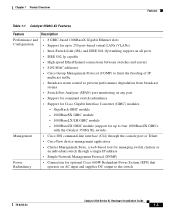
... IP multicast traffic • Broadcast storm control to prevent performance degradation from broadcast storms • Switch Port Analyzer (SPAN) port monitoring on AC input and supplies DC output to four 1000BaseZX GBICs with the Catalyst 3508G XL switch) Management • Cisco IOS command-line interface (CLI) through the console port or Telnet • CiscoView device-management application • Cluster Management Suite, a web-based tool for managing switch clusters or an individual switch through a single IP address • Simple Network Management Protocol (SNMP) Power...
... IP multicast traffic • Broadcast storm control to prevent performance degradation from broadcast storms • Switch Port Analyzer (SPAN) port monitoring on AC input and supplies DC output to four 1000BaseZX GBICs with the Catalyst 3508G XL switch) Management • Cisco IOS command-line interface (CLI) through the console port or Telnet • CiscoView device-management application • Cluster Management Suite, a web-based tool for managing switch clusters or an individual switch through a single IP address • Simple Network Management Protocol (SNMP) Power...
Hardware Installation Guide
Page 24
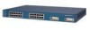
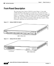
... MODE STATUS UTIL DUPLX SPEED 2 3 4 5 6 7 8 GBIC module slots Figure 1-3 Catalyst 3512 XL Switch 12 1X 34 56 78 SYSTEM MODE RPS 2X STATUS UTIL DUPLX SPEED 9 10 11 12 11X 12X 10/100 ports 1 2 GBIC module slots 26235 Catalyst 3500 Series XL Hardware Installation Guide 1-6 78-6456-03 Front-Panel Description Chapter 1 Product Overview Front-Panel Description The front panel of LEDs and a Mode button. (The Catalyst 3548 XL switch has a Mode...
... MODE STATUS UTIL DUPLX SPEED 2 3 4 5 6 7 8 GBIC module slots Figure 1-3 Catalyst 3512 XL Switch 12 1X 34 56 78 SYSTEM MODE RPS 2X STATUS UTIL DUPLX SPEED 9 10 11 12 11X 12X 10/100 ports 1 2 GBIC module slots 26235 Catalyst 3500 Series XL Hardware Installation Guide 1-6 78-6456-03 Front-Panel Description Chapter 1 Product Overview Front-Panel Description The front panel of LEDs and a Mode button. (The Catalyst 3548 XL switch has a Mode...

Hardware Installation Guide
Page 26
...; 100BaseTX-compatible devices such as high-speed workstations, Cisco IP Phones, servers, hubs, routers, and other switches through , twisted-pair cable. Pinouts for autonegotiation, the port can be sure that both devices support and full-duplex transmission, if the attached device supports it) and configures itself accordingly. Catalyst 3500 Series XL Hardware Installation Guide 1-8 78-6456-03 When set for the cables are described in Figure 1-3, Figure 1-4, Figure 1-5, and...
...; 100BaseTX-compatible devices such as high-speed workstations, Cisco IP Phones, servers, hubs, routers, and other switches through , twisted-pair cable. Pinouts for autonegotiation, the port can be sure that both devices support and full-duplex transmission, if the attached device supports it) and configures itself accordingly. Catalyst 3500 Series XL Hardware Installation Guide 1-8 78-6456-03 When set for the cables are described in Figure 1-3, Figure 1-4, Figure 1-5, and...
Hardware Installation Guide
Page 28
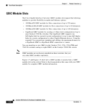
... fiber connections of up to 550 meters. • 1000BaseLX/LH GBIC module for fiber connections of up to 10 kilometers. • 1000BaseZX GBIC module for fiber connections of up to eight GBICs in the Catalyst 3508G XL switch. You can order GBIC modules separately. The GigaStack GBIC supports one full-duplex link (in a point-to-point configuration) or up to nine half-duplex links (in a stack configuration) to other Gigabit Ethernet...
... fiber connections of up to 550 meters. • 1000BaseLX/LH GBIC module for fiber connections of up to 10 kilometers. • 1000BaseZX GBIC module for fiber connections of up to eight GBICs in the Catalyst 3508G XL switch. You can order GBIC modules separately. The GigaStack GBIC supports one full-duplex link (in a point-to-point configuration) or up to nine half-duplex links (in a stack configuration) to other Gigabit Ethernet...
Hardware Installation Guide
Page 34
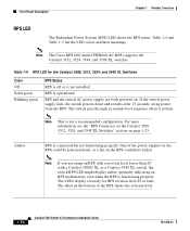
... not a recommended configuration. Table 1-4 RPS LED for RPS revision level Z3 or later. Front-Panel Description Chapter 1 Product Overview RPS LED The Redundant Power System (RPS) LED shows the RPS status. RPS and the switch AC power supply are using power from the RPS. Note This is not installed. One of the RPS shows the revision level. 1-16 Catalyst 3500 Series XL Hardware Installation Guide 78-6456-03...
... not a recommended configuration. Table 1-4 RPS LED for RPS revision level Z3 or later. Front-Panel Description Chapter 1 Product Overview RPS LED The Redundant Power System (RPS) LED shows the RPS status. RPS and the switch AC power supply are using power from the RPS. Note This is not installed. One of the RPS shows the revision level. 1-16 Catalyst 3500 Series XL Hardware Installation Guide 78-6456-03...

Hardware Installation Guide
Page 36
... in the Catalyst 3548 XL switch, press the Mode label. Table 1-6 Port Mode LEDs Mode LED STAT UTL DUPLX SPEED LINE PWR Port Mode Port status Switch utilization Port duplex mode Port speed Port inline power Description The port status. The port operating speed: 10, 100, or 1000 Mbps. When you change the port mode in use by the switch. The port duplex mode: full duplex or half duplex. The inline power status: on or off. 1-18 Catalyst 3500 Series XL Hardware Installation Guide 78-6456-03 Note To change the port mode. To select or change port modes, the...
... in the Catalyst 3548 XL switch, press the Mode label. Table 1-6 Port Mode LEDs Mode LED STAT UTL DUPLX SPEED LINE PWR Port Mode Port status Switch utilization Port duplex mode Port speed Port inline power Description The port status. The port operating speed: 10, 100, or 1000 Mbps. When you change the port mode in use by the switch. The port duplex mode: full duplex or half duplex. The inline power status: on or off. 1-18 Catalyst 3500 Series XL Hardware Installation Guide 78-6456-03 Note To change the port mode. To select or change port modes, the...

Hardware Installation Guide
Page 45
... connected to your SNMP application for these applications. • Cisco IOS command-line interface (CLI) Connect a PC or terminal directly to the console port, located on the rear panel of the switch, to access the CLI. You use to create, monitor, and configure a cluster of switches or an individual switch. For more information, refer to the Cisco IOS Desktop Switching Software Configuration Guide and the online help for more information. • Simple Network Management Protocol (SNMP) network management You can manage switches from a remote...
... connected to your SNMP application for these applications. • Cisco IOS command-line interface (CLI) Connect a PC or terminal directly to the console port, located on the rear panel of the switch, to access the CLI. You use to create, monitor, and configure a cluster of switches or an individual switch. For more information, refer to the Cisco IOS Desktop Switching Software Configuration Guide and the online help for more information. • Simple Network Management Protocol (SNMP) network management You can manage switches from a remote...

Hardware Installation Guide
Page 47
... same logical network as the users who access those resources most. • Use full-duplex operation between the switch and its connected workstations. • The increased power of service (QoS) to prioritize applications such as IP telephony during congestion and to prioritize voice and data traffic as either high or low priority based on 802.1p/Q. 78-6456-03 Catalyst 3500 Series XL Hardware Installation Guide 1-29
... same logical network as the users who access those resources most. • Use full-duplex operation between the switch and its connected workstations. • The increased power of service (QoS) to prioritize applications such as IP telephony during congestion and to prioritize voice and data traffic as either high or low priority based on 802.1p/Q. 78-6456-03 Catalyst 3500 Series XL Hardware Installation Guide 1-29

Hardware Installation Guide
Page 48
... address. • High-performance workgroup-For users who require high-speed access to network resources, use a stack of up to 100 km • Redundant gigabit backbone-To enhance network reliability and load balancing for using Fast Ethernet or gigabit links or Fast EtherChannel or Gigabit EtherChannel links. Each switch in this with the switches in case one of the redundant connections fails, the other devices and create backup paths by using the Catalyst 3500 XL switches...
... address. • High-performance workgroup-For users who require high-speed access to network resources, use a stack of up to 100 km • Redundant gigabit backbone-To enhance network reliability and load balancing for using Fast Ethernet or gigabit links or Fast EtherChannel or Gigabit EtherChannel links. Each switch in this with the switches in case one of the redundant connections fails, the other devices and create backup paths by using the Catalyst 3500 XL switches...
Hardware Installation Guide
Page 52
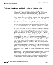
... Catalyst switches except the Catalyst 4908G-L3 switch. Cisco CallManager controls call -processing server running Cisco SoftPhone software can manage a cluster through , twisted-pair cable with workstations running Cisco CallManager software, a Dynamic Host Configuration Protocol (DHCP)/Bootstrap Protocol (BOOTP) server, or an IPTV multicast server). 1-34 Catalyst 3500 Series XL Hardware Installation Guide 78-6456-03 IP phones connected to voice traffic over data traffic. You can receive redundant power when it also is connected. This network uses a collapsed backbone and switch...
... Catalyst switches except the Catalyst 4908G-L3 switch. Cisco CallManager controls call -processing server running Cisco SoftPhone software can manage a cluster through , twisted-pair cable with workstations running Cisco CallManager software, a Dynamic Host Configuration Protocol (DHCP)/Bootstrap Protocol (BOOTP) server, or an IPTV multicast server). 1-34 Catalyst 3500 Series XL Hardware Installation Guide 78-6456-03 IP phones connected to voice traffic over data traffic. You can receive redundant power when it also is connected. This network uses a collapsed backbone and switch...

Hardware Installation Guide
Page 57
... chapter describes how to install and start up your Catalyst 3500 XL switches and to interpret the power-on self-test (POST) that they are presented: • Pre-installation information and guidelines • Installation procedures • Power-on procedures • Connection procedures • Set up procedures for initial configuration • Default configuration settings • Where to go next 78-6456-03 Catalyst 3500 Series XL Hardware Installation Guide 2-1
... chapter describes how to install and start up your Catalyst 3500 XL switches and to interpret the power-on self-test (POST) that they are presented: • Pre-installation information and guidelines • Installation procedures • Power-on procedures • Connection procedures • Set up procedures for initial configuration • Default configuration settings • Where to go next 78-6456-03 Catalyst 3500 Series XL Hardware Installation Guide 2-1

Hardware Installation Guide
Page 72
... switch is operational. If a test fails, the port LED associated with the test turns amber, and the system LED turns amber. If POST fails, refer to Chapter 3, "Troubleshooting," to determine a course of the connection. If the attached ports do not support autonegotiation, you must wait 10 seconds before link has been established, you can reduce performance or result in damage to that have their speed and duplex parameters manually set...
... switch is operational. If a test fails, the port LED associated with the test turns amber, and the system LED turns amber. If POST fails, refer to Chapter 3, "Troubleshooting," to determine a course of the connection. If the attached ports do not support autonegotiation, you must wait 10 seconds before link has been established, you can reduce performance or result in damage to that have their speed and duplex parameters manually set...
Hardware Installation Guide
Page 80
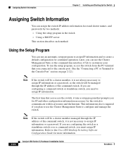
... first time that you access the switch, it runs a setup program that you plan to use the Cluster Management Suite or the command-line interface (CLI) to the Cisco IOS Desktop Switching Software Configuration Guide for the switch to configure and manage the switch. Note If the switch will be managed through the IP address of the command switch. This information also is required if you connected to the console port. (See the "Connecting a PC or Terminal to the Console Port...
... first time that you access the switch, it runs a setup program that you plan to use the Cluster Management Suite or the command-line interface (CLI) to the Cisco IOS Desktop Switching Software Configuration Guide for the switch to configure and manage the switch. Note If the switch will be managed through the IP address of the command switch. This information also is required if you connected to the console port. (See the "Connecting a PC or Terminal to the Console Port...

Hardware Installation Guide
Page 86
...ARP = Address Resolution Protocol 3. VLAN = Virtual Local Area Network 4. You can use any of the following management options to configure the switch from the console. Disabled. Where to Go Next Chapter 2 Installing and Starting Up the Switch Table 2-1 Default Configuration Settings (continued) Feature Diagnostics SPAN5 port monitoring Console, buffer, and file logging Security Password Addressing security Trap manager Community strings Port security Inline Power Inline power mode 1. Auto. CGMP = Cisco Group Management Protocol 5. SPAN = Switched Port Analyzer Default Setting...
...ARP = Address Resolution Protocol 3. VLAN = Virtual Local Area Network 4. You can use any of the following management options to configure the switch from the console. Disabled. Where to Go Next Chapter 2 Installing and Starting Up the Switch Table 2-1 Default Configuration Settings (continued) Feature Diagnostics SPAN5 port monitoring Console, buffer, and file logging Security Password Addressing security Trap manager Community strings Port security Inline Power Inline power mode 1. Auto. CGMP = Cisco Group Management Protocol 5. SPAN = Switched Port Analyzer Default Setting...

Hardware Installation Guide
Page 87
... Switching Software Configuration Guide, the Cisco IOS Desktop Switching Command Reference (online only), or the documentation that came with your SNMP application for troubleshooting problems: • Understanding POST results • Diagnosing problems 78-6456-03 Catalyst 3500 Series XL Hardware Installation Guide 3-1 For a full description of the switch LEDs, see the "LEDs" section on page 1-12. You can also get statistics from the browser interface, from the command-line interface (CLI), or from an Simple Network Management Protocol (SNMP...
... Switching Software Configuration Guide, the Cisco IOS Desktop Switching Command Reference (online only), or the documentation that came with your SNMP application for troubleshooting problems: • Understanding POST results • Diagnosing problems 78-6456-03 Catalyst 3500 Series XL Hardware Installation Guide 3-1 For a full description of the switch LEDs, see the "LEDs" section on page 1-12. You can also get statistics from the browser interface, from the command-line interface (CLI), or from an Simple Network Management Protocol (SNMP...

Hardware Installation Guide
Page 92
... one failed fan. Make sure the switch is connected to the LAN-to 45°C). - If it does: - Cisco IP Phone fails to check if an overtemperature condition exists. Resolution • Either check the switch itself or use the show env command to power on the Cisco IP Phone. Replace the switch at your convenience. • Use the show env command to a Catalyst 3524-PWR XL switch. Catalyst 3500 Series XL Hardware Installation Guide...
... one failed fan. Make sure the switch is connected to the LAN-to 45°C). - If it does: - Cisco IP Phone fails to check if an overtemperature condition exists. Resolution • Either check the switch itself or use the show env command to power on the Cisco IP Phone. Replace the switch at your convenience. • Use the show env command to a Catalyst 3524-PWR XL switch. Catalyst 3500 Series XL Hardware Installation Guide...


