Hardware Installation Guide
Page 21
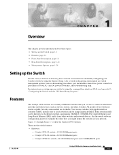
... by using Gigastack GBICs. You can use switches with the CLI-Based Setup Program." Catalyst 2950-24 switch-24 10/100 Ethernet ports - Some switch models can be deployed as servers, routers, and other switches and network devices. These are stackable. and DC-powered switches, and troubleshooting help. Features The Catalyst 2950 switches are switch management options, basic rack-mounting procedures, port and module...
... by using Gigastack GBICs. You can use switches with the CLI-Based Setup Program." Catalyst 2950-24 switch-24 10/100 Ethernet ports - Some switch models can be deployed as servers, routers, and other switches and network devices. These are stackable. and DC-powered switches, and troubleshooting help. Features The Catalyst 2950 switches are switch management options, basic rack-mounting procedures, port and module...

Hardware Installation Guide
Page 22
...100 Ethernet ports and 2 GBIC module slots - Catalyst 2950SX-24 switch-24 10/100 Ethernet ports and 2 1000BASE-SX ports - For 10/100 ports, autonegotiates the speed and duplex settings - Catalyst 2950G-24-EI-DC-24 10/100 Ethernet ports and 2 GBIC module ...Catalyst 2950T-24 switch, autonegotiates the speed and supports only full-duplex mode - For 10/100/1000 ports on the Catalyst 2950T-48-SI and 2950 LRE switches, autonegotiates the speed and duplex setting when operating at one time.) Note See the Catalyst 2950 LRE switch release notes for the Catalyst 2950 LRE switches. - Catalyst...
...100 Ethernet ports and 2 GBIC module slots - Catalyst 2950SX-24 switch-24 10/100 Ethernet ports and 2 1000BASE-SX ports - For 10/100 ports, autonegotiates the speed and duplex settings - Catalyst 2950G-24-EI-DC-24 10/100 Ethernet ports and 2 GBIC module ...Catalyst 2950T-24 switch, autonegotiates the speed and supports only full-duplex mode - For 10/100/1000 ports on the Catalyst 2950T-48-SI and 2950 LRE switches, autonegotiates the speed and duplex setting when operating at one time.) Note See the Catalyst 2950 LRE switch release notes for the Catalyst 2950 LRE switches. - Catalyst...

Hardware Installation Guide
Page 23
... Catalyst 2950 Switch Hardware Installation Guide 1-3 Chapter 1 Overview Front-Panel Description • Power redundancy - Connection for an optional Cisco RPS 675 that the CPE is supported by the switch. Table 1-1 LRE Switch and CPE Compatibility Matrix LRE Devices Catalyst 2950ST-8 LRE Cisco 575 LRE Yes CPE Cisco 576 LRE 997 No CPE Cisco 585 LRE Yes CPE Catalyst 2950ST-24 LRE Catalyst 2950ST-24...
... Catalyst 2950 Switch Hardware Installation Guide 1-3 Chapter 1 Overview Front-Panel Description • Power redundancy - Connection for an optional Cisco RPS 675 that the CPE is supported by the switch. Table 1-1 LRE Switch and CPE Compatibility Matrix LRE Devices Catalyst 2950ST-8 LRE Cisco 575 LRE Yes CPE Cisco 576 LRE 997 No CPE Cisco 585 LRE Yes CPE Catalyst 2950ST-24 LRE Catalyst 2950ST-24...

Hardware Installation Guide
Page 24
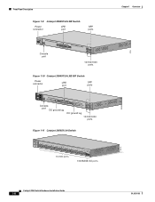
Front-Panel Description Figure 1-2 Catalyst 2950-24 Switch SYST RPS STAT UTIL DUPLX SPEED MODE 1 2 3 4x 5x 6x 7x 8x 9x 10x 11x 10Base-T / 100Base-TX 12x 13x 14x 15x 16x 17x 18x 19x 20x 21x 22x 23x Catalyst 2950 SERIES 24x 10/100 ports Figure 1-3 Catalyst 2950C-24 Switch SYST RPS STAT UTIL DUPLX SPEED MODE 1x 2x 3x...
Front-Panel Description Figure 1-2 Catalyst 2950-24 Switch SYST RPS STAT UTIL DUPLX SPEED MODE 1 2 3 4x 5x 6x 7x 8x 9x 10x 11x 10Base-T / 100Base-TX 12x 13x 14x 15x 16x 17x 18x 19x 20x 21x 22x 23x Catalyst 2950 SERIES 24x 10/100 ports Figure 1-3 Catalyst 2950C-24 Switch SYST RPS STAT UTIL DUPLX SPEED MODE 1x 2x 3x...
Hardware Installation Guide
Page 26
... 2 3 4 5 6 7 8 9 10 11 12 Console port DC ground lug 13 14 15 16 17 18 19 20 21 22 23 24 Catalyst 2950 SERIES LRE 997 1 2 1 2 DC ground lug 10/100/1000 ports Figure 1-11 Catalyst 2950SX-24 Switch SYST RPS STAT UTIL DUPLX SPEED MODE 1x 2x 3x 4x 5x 6x 7x 8x 9x 10x 11x 10BASE...-T / 100BASE-TX 12x 13x 14x 15x 16x 17x 18x 19x 20x 21x 22x 23x Catalyst 2950 SERIES 24x 1000BASE-SX 25 26 10/100 ...
... 2 3 4 5 6 7 8 9 10 11 12 Console port DC ground lug 13 14 15 16 17 18 19 20 21 22 23 24 Catalyst 2950 SERIES LRE 997 1 2 1 2 DC ground lug 10/100/1000 ports Figure 1-11 Catalyst 2950SX-24 Switch SYST RPS STAT UTIL DUPLX SPEED MODE 1x 2x 3x 4x 5x 6x 7x 8x 9x 10x 11x 10BASE...-T / 100BASE-TX 12x 13x 14x 15x 16x 17x 18x 19x 20x 21x 22x 23x Catalyst 2950 SERIES 24x 1000BASE-SX 25 26 10/100 ...
Hardware Installation Guide
Page 27
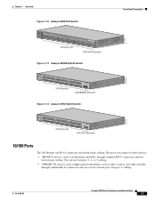
...such as high-speed workstations, servers, hubs, routers, and other switches, through standard RJ-45 connectors and two twisted-pair cabling. OL-6156-01 Catalyst 2950 Switch Hardware Installation Guide 1-7 Chapter 1 Overview Figure 1-12 Catalyst 2950T-24 Switch Front-Panel Description 47337 SYST RPS STAT UTIL DUPLX SPEED MODE 1x... 100Base-TX 12x 13x 14x 15x 16x 17x 18x 19x 20x 21x 22x 23x Catalyst 2950 SERIES 24x 10/100/100Base-T 1 2 10/100 ports 10/100/1000 ports Figure 1-13 Catalyst 2950SX-48-SI Switch 97630 SYST RPS STAT UTIL DUPLX SPEED MODE 1 1X 2X 23 45 67 ...
...such as high-speed workstations, servers, hubs, routers, and other switches, through standard RJ-45 connectors and two twisted-pair cabling. OL-6156-01 Catalyst 2950 Switch Hardware Installation Guide 1-7 Chapter 1 Overview Figure 1-12 Catalyst 2950T-24 Switch Front-Panel Description 47337 SYST RPS STAT UTIL DUPLX SPEED MODE 1x... 100Base-TX 12x 13x 14x 15x 16x 17x 18x 19x 20x 21x 22x 23x Catalyst 2950 SERIES 24x 10/100/100Base-T 1 2 10/100 ports 10/100/1000 ports Figure 1-13 Catalyst 2950SX-48-SI Switch 97630 SYST RPS STAT UTIL DUPLX SPEED MODE 1 1X 2X 23 45 67 ...
Hardware Installation Guide
Page 28
... on how to identify a crossover cable, go to the "Identifying a Crossover Cable" section on the Catalyst 2950T-48-SI and Catalyst 2950 LRE switches can also be explicitly set for the cables are described in full-duplex mode. When set to operate ...Catalyst 2950T-24, Catalyst 2950T-48-SI, and Catalyst 2950 LRE switches use a four twisted-pair, Category 5 cable. When connecting the switch to operate at 10, 100, or 1000 Mbps, but only in full- For information on how to identify a crossover cable, go to the "Identifying a Crossover Cable" section on the Catalyst 2950T-24 switch...
... on how to identify a crossover cable, go to the "Identifying a Crossover Cable" section on the Catalyst 2950T-48-SI and Catalyst 2950 LRE switches can also be explicitly set for the cables are described in full-duplex mode. When set to operate ...Catalyst 2950T-24, Catalyst 2950T-48-SI, and Catalyst 2950 LRE switches use a four twisted-pair, Category 5 cable. When connecting the switch to operate at 10, 100, or 1000 Mbps, but only in full- For information on how to identify a crossover cable, go to the "Identifying a Crossover Cable" section on the Catalyst 2950T-24 switch...
Hardware Installation Guide
Page 29
... LRE port is speed autosensing and half-duplex operation. Certain Catalyst 2950 LRE switches support certain Cisco LRE CPE devices. You can connect the Cisco 575 LRE CPE and Cisco 585 LRE CPE devices to 15 Mbps (full duplex) over the copper connections in Table 2-1 to 24 Cisco LRE CPE devices through structured or unstructured wiring, such as...
... LRE port is speed autosensing and half-duplex operation. Certain Catalyst 2950 LRE switches support certain Cisco LRE CPE devices. You can connect the Cisco 575 LRE CPE and Cisco 585 LRE CPE devices to 15 Mbps (full duplex) over the copper connections in Table 2-1 to 24 Cisco LRE CPE devices through structured or unstructured wiring, such as...

Hardware Installation Guide
Page 33
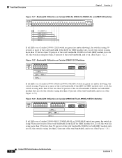
... Catalyst 2950-12, 2950-24, 2950C-24, 2950SX-24, and 2950T-24 switches • Figure 1-16 for the Catalyst 2950G-12-EI, 2950G-24-EI, and 2950G-24-EI-DC switches • Figure 1-17 for the Catalyst 2950G-48-EI, Catalyst 2950SX-48-SI, and Catalyst 2950T-48-SI switches • Figure 1-18 for the Catalyst 2950ST-8 LRE and 2950ST-24 LRE switches • Figure 1-19 for the Catalyst 2950ST-24 LRE 997 switches...
... Catalyst 2950-12, 2950-24, 2950C-24, 2950SX-24, and 2950T-24 switches • Figure 1-16 for the Catalyst 2950G-12-EI, 2950G-24-EI, and 2950G-24-EI-DC switches • Figure 1-17 for the Catalyst 2950G-48-EI, Catalyst 2950SX-48-SI, and Catalyst 2950T-48-SI switches • Figure 1-18 for the Catalyst 2950ST-8 LRE and 2950ST-24 LRE switches • Figure 1-19 for the Catalyst 2950ST-24 LRE 997 switches...

Hardware Installation Guide
Page 37
...LED background on . DUPLX Port duplex mode The port duplex mode: half duplex or full duplex. Table 1-7 explains how to Figure 1-24 for details. Solid green Link present. UTIL (utilization) Green The current backplane utilization that is the default mode. Alternating green-amber Link...and errors such as excessive collisions, CRC errors, and alignment and jabber errors are off when the MODE is sending or receiving data. A Catalyst 2950 LRE switch does not have a UTIL or a DUPLX LED. Table 1-6 explains how to SPEED. Table 1-6 Meaning of the port LED colors change...
...LED background on . DUPLX Port duplex mode The port duplex mode: half duplex or full duplex. Table 1-7 explains how to Figure 1-24 for details. Solid green Link present. UTIL (utilization) Green The current backplane utilization that is the default mode. Alternating green-amber Link...and errors such as excessive collisions, CRC errors, and alignment and jabber errors are off when the MODE is sending or receiving data. A Catalyst 2950 LRE switch does not have a UTIL or a DUPLX LED. Table 1-6 explains how to SPEED. Table 1-6 Meaning of the port LED colors change...
Hardware Installation Guide
Page 39
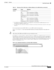
... total bandwidth. (See Figure 1-20 and Figure 1-21.) Figure 1-20 Bandwidth Utilization on a Catalyst 2950-12, 2950-24, 2950C-24, 2950SX-24, or 2950T-24 switch are green (no amber showing), the switch is using 50 percent or more of the total bandwidth. If an LRE switch senses connections to the 10/100/1000 port, depending on . If all LEDs on...
... total bandwidth. (See Figure 1-20 and Figure 1-21.) Figure 1-20 Bandwidth Utilization on a Catalyst 2950-12, 2950-24, 2950C-24, 2950SX-24, or 2950T-24 switch are green (no amber showing), the switch is using 50 percent or more of the total bandwidth. If an LRE switch senses connections to the 10/100/1000 port, depending on . If all LEDs on...
Hardware Installation Guide
Page 40
... LEDs for GBIC module slot 2 is off , the switch is using less than 50 percent of the total bandwidth. Front-Panel Description Chapter 1 Overview Figure 1-21 Bandwidth Utilization on Catalyst 2950-24, 2950C-24, 2950SX-24, and 2950T-24 Switches SYST RPS STAT UTIL DUPLX SPEED MODE 1x 2x 3x 4x... 5x 6x 7x 8x 10Base-T / 100Base-TX 9x 10x 11x 12x 13x 14x 15x 16x Catalyst 2950 SERIES 17x 18x 19x 20x 21x 22x ...
... LEDs for GBIC module slot 2 is off , the switch is using less than 50 percent of the total bandwidth. Front-Panel Description Chapter 1 Overview Figure 1-21 Bandwidth Utilization on Catalyst 2950-24, 2950C-24, 2950SX-24, and 2950T-24 Switches SYST RPS STAT UTIL DUPLX SPEED MODE 1x 2x 3x 4x... 5x 6x 7x 8x 10Base-T / 100Base-TX 9x 10x 11x 12x 13x 14x 15x 16x Catalyst 2950 SERIES 17x 18x 19x 20x 21x 22x ...

Hardware Installation Guide
Page 41
...connector Fan exhaust CONSOLE RJ-45 console port OL-6156-01 Catalyst 2950 Switch Hardware Installation Guide 1-21 Chapter 1 Overview Rear-Panel Description Figure 1-24 Bandwidth Utilization on Catalyst 2950G-48-EI, 2950SX-48-SI, and 2950T-48-SI Switches 65510 Catalyst 2950 12 1X 3 24 56 78 9 10 11 12 13 14 15 16 15X... 17 18 17X 19 20 21 22 23 24 25 26 27 28 29 31 31...
...connector Fan exhaust CONSOLE RJ-45 console port OL-6156-01 Catalyst 2950 Switch Hardware Installation Guide 1-21 Chapter 1 Overview Rear-Panel Description Figure 1-24 Bandwidth Utilization on Catalyst 2950G-48-EI, 2950SX-48-SI, and 2950T-48-SI Switches 65510 Catalyst 2950 12 1X 3 24 56 78 9 10 11 12 13 14 15 16 15X... 17 18 17X 19 20 21 22 23 24 25 26 27 28 29 31 31...
Hardware Installation Guide
Page 53
... to the Switch, page 2-8 2. You can install other Catalyst 2950 switches in a rack as examples. Attaching the Optional Cable Guide, page 2-16 Note Installing a Catalyst 2950G-48-EI, Catalyst 2950SX-48-SI, or Catalyst 2950T-48-SI switch in a 23-inch or 24-inch rack ...Switch on a Wall, page 2-17 • Installing the Optional AC Ground Kit for Catalyst 2950 Switches, page 2-19 Installing the Switch in a Rack Use these instructions to install the switch in a rack: Warning To prevent bodily injury when mounting or servicing this unit in a partially filled rack, load the rack from Cisco...
... to the Switch, page 2-8 2. You can install other Catalyst 2950 switches in a rack as examples. Attaching the Optional Cable Guide, page 2-16 Note Installing a Catalyst 2950G-48-EI, Catalyst 2950SX-48-SI, or Catalyst 2950T-48-SI switch in a 23-inch or 24-inch rack ...Switch on a Wall, page 2-17 • Installing the Optional AC Ground Kit for Catalyst 2950 Switches, page 2-19 Installing the Switch in a Rack Use these instructions to install the switch in a rack: Warning To prevent bodily injury when mounting or servicing this unit in a partially filled rack, load the rack from Cisco...
Hardware Installation Guide
Page 73
...-24 switches operate at 10 or 100 Mbps in either half- If the attached devices do not support autonegotiation, you can reduce performance or result in link failures between the devices. Note On the Catalyst 2950 LRE switches, the four input uplink ports are bundled as two logical ports, each logical port, you can set...
...-24 switches operate at 10 or 100 Mbps in either half- If the attached devices do not support autonegotiation, you can reduce performance or result in link failures between the devices. Note On the Catalyst 2950 LRE switches, the four input uplink ports are bundled as two logical ports, each logical port, you can set...
Hardware Installation Guide
Page 74
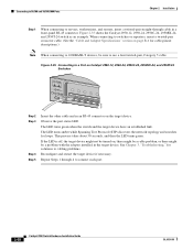
Figure 2-35 shows the Catalyst 2950-12, 2950-24, 2950C-24, 2950SX-24, and 2950T-24 switch as an example. Figure 2-35 Connecting to a Port on Catalyst 2950-12, 2950-24, 2950C-24, 2950SX-24, and 2950T-24 Switches SYST RPS STAT UTIL DUPLX SPEED MODE 1x 2x 3x 4x 5x 45576 Step 2 Step 3 Step 4 Step 5 Insert the other cable end in the target ...
Figure 2-35 shows the Catalyst 2950-12, 2950-24, 2950C-24, 2950SX-24, and 2950T-24 switch as an example. Figure 2-35 Connecting to a Port on Catalyst 2950-12, 2950-24, 2950C-24, 2950SX-24, and 2950T-24 Switches SYST RPS STAT UTIL DUPLX SPEED MODE 1x 2x 3x 4x 5x 45576 Step 2 Step 3 Step 4 Step 5 Insert the other cable end in the target ...
Hardware Installation Guide
Page 77
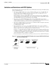
... POTS Splitter. • The Catalyst 2950ST-24 LRE 997 switch and Cisco 576 LRE 997 CPE are designed to share lines with analog, ISDN, and digital PBX switch telephones that use a Cisco LRE 48 POTS Splitter with Catalyst 2950 LRE switches and Cisco LRE CPE devices: • The Catalyst 2950ST-8 LRE switch, Catalyst 2950ST-24 LRE switch, Cisco 575 LRE CPE, and Cisco 585 LRE CPE are...
... POTS Splitter. • The Catalyst 2950ST-24 LRE 997 switch and Cisco 576 LRE 997 CPE are designed to share lines with analog, ISDN, and digital PBX switch telephones that use a Cisco LRE 48 POTS Splitter with Catalyst 2950 LRE switches and Cisco LRE CPE devices: • The Catalyst 2950ST-8 LRE switch, Catalyst 2950ST-24 LRE switch, Cisco 575 LRE CPE, and Cisco 585 LRE CPE are...

Hardware Installation Guide
Page 91
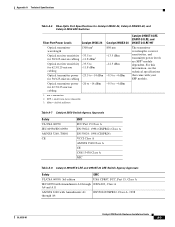
... A-1 through Table A-5 list the technical specifications for the Cisco RPS 675 +12 V @4.5 A Power consumption 30 W (maximum) 102 Btus per hour Power rating Physical Dimensions 0.05 kVA Weight 6.5 lb (3 kg) Dimensions (H x W x D) 1.72 x 17.5 x 9.52 in . Table A-1 Technical Specifications for Catalyst 2950-12, 2950-24, 2950C-24, 2950SX-24, and 2950T-24 Switches Environmental Ranges Operating temperature 32 to 113°F (0 to...
... A-1 through Table A-5 list the technical specifications for the Cisco RPS 675 +12 V @4.5 A Power consumption 30 W (maximum) 102 Btus per hour Power rating Physical Dimensions 0.05 kVA Weight 6.5 lb (3 kg) Dimensions (H x W x D) 1.72 x 17.5 x 9.52 in . Table A-1 Technical Specifications for Catalyst 2950-12, 2950-24, 2950C-24, 2950SX-24, and 2950T-24 Switches Environmental Ranges Operating temperature 32 to 113°F (0 to...
Hardware Installation Guide
Page 95
..., Class A IEC 60950 with Amendments A1 through A4 EN55022/CISPR22, Class A, 1998 OL-6156-01 Catalyst 2950 Switch Hardware Installation Guide A-5 Appendix A Technical Specifications Table A-6 Fiber-Optic Port Specifications for Catalyst 2950C-24, Catalyst 2950SX-24, and Catalyst 2950 LRE Switches Fiber-Port Power Levels Catalyst 2950C-24 Optical transmitter wavelength 1300 nm1 Optical receiver sensitivity -33.5 to for 50/125-micron cabling...
..., Class A IEC 60950 with Amendments A1 through A4 EN55022/CISPR22, Class A, 1998 OL-6156-01 Catalyst 2950 Switch Hardware Installation Guide A-5 Appendix A Technical Specifications Table A-6 Fiber-Optic Port Specifications for Catalyst 2950C-24, Catalyst 2950SX-24, and Catalyst 2950 LRE Switches Fiber-Port Power Levels Catalyst 2950C-24 Optical transmitter wavelength 1300 nm1 Optical receiver sensitivity -33.5 to for 50/125-micron cabling...
Hardware Installation Guide
Page 100
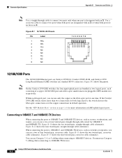
...100/1000 port and a fiber-optic small form-factor pluggable (SFP) module slot, respectively. Figure B-11 shows the two twisted-pair, crossover cable schematics. Catalyst 2950 Switch Hardware Installation Guide B-2 OL-6156-01 Figure B-1 10/100 RJ-45 Pinouts Pin Label 1 RD+ 2 RD- 3 TD+ 4 NC 5 NC 6 .... When connecting the ports to 100BASE-TX devices. See the "SFP Module Slots" section on Catalyst 2950T-24, Catalyst 2950T-48-SI, and Catalyst 2950 Long-Reach Ethernet (LRE) switches use only the copper or the fiber-optic port at one port is designated with an X or...
...100/1000 port and a fiber-optic small form-factor pluggable (SFP) module slot, respectively. Figure B-11 shows the two twisted-pair, crossover cable schematics. Catalyst 2950 Switch Hardware Installation Guide B-2 OL-6156-01 Figure B-1 10/100 RJ-45 Pinouts Pin Label 1 RD+ 2 RD- 3 TD+ 4 NC 5 NC 6 .... When connecting the ports to 100BASE-TX devices. See the "SFP Module Slots" section on Catalyst 2950T-24, Catalyst 2950T-48-SI, and Catalyst 2950 Long-Reach Ethernet (LRE) switches use only the copper or the fiber-optic port at one port is designated with an X or...


