Service Manual
Page 3
...printer"). This manual consists of the laser printer (hereinafter referred to find the cause of rollers, Connection diagrams, PCB circuit diagrams, etc. CHAPTER 5: MAINTENANCE Periodical replacements parts, consumable parts, etc. This service manual covers the HL-1030/1240/1250/1270N printers...electrical system and the electrical circuits and their timing information. descriptions, Drum life & page counter, Diameter / circumference of problems. i A thorough understanding of this printer, based on information in this service manual and service information bulletins,...
...printer"). This manual consists of the laser printer (hereinafter referred to find the cause of rollers, Connection diagrams, PCB circuit diagrams, etc. CHAPTER 5: MAINTENANCE Periodical replacements parts, consumable parts, etc. This service manual covers the HL-1030/1240/1250/1270N printers...electrical system and the electrical circuits and their timing information. descriptions, Drum life & page counter, Diameter / circumference of problems. i A thorough understanding of this printer, based on information in this service manual and service information bulletins,...

Service Manual
Page 4
...INSTALLATION 2-1 1.1 Power Supply...2-1 1.2 Environment...2-1 1.3 System Requirements for Brother Printer Solution for Windows® 98 only 2-7 3.3.1 Connect the USB interface cable 2-7 3.3.2 Install the USB driver ...2-7 3.3.3 Set the PC printer port ...2-9 3.4 For Macintosh (iMac and Power Macintosh) with USB ... Windows® Users with No CD-ROM Drive 2-5 3.2.1 Install the drum unit...2-5 3.2.2 Load paper...2-5 3.2.3 Print a test page...2-5 3.2.4 Connect the printer and the computer 2-6 3.2.5 Install the printer driver from floppy disk 2-6 3.3 Using the USB Interface (for Windows ...
...INSTALLATION 2-1 1.1 Power Supply...2-1 1.2 Environment...2-1 1.3 System Requirements for Brother Printer Solution for Windows® 98 only 2-7 3.3.1 Connect the USB interface cable 2-7 3.3.2 Install the USB driver ...2-7 3.3.3 Set the PC printer port ...2-9 3.4 For Macintosh (iMac and Power Macintosh) with USB ... Windows® Users with No CD-ROM Drive 2-5 3.2.1 Install the drum unit...2-5 3.2.2 Load paper...2-5 3.2.3 Print a test page...2-5 3.2.4 Connect the printer and the computer 2-6 3.2.5 Install the printer driver from floppy disk 2-6 3.3 Using the USB Interface (for Windows ...
Service Manual
Page 5
... ...3-23 2.2.2 Paper registration...3-23 iii CONTROL PANEL OPERATION 2-13 5.1 Ready (Paper) LED Indications 2-13 5.2 Data (Toner) LED Indications 2-14 5.3 Drum LED Indications ...2-14 5.4 Alarm LED Indications ...2-14 5.5 Control Panel Button Operations 2-15 5.6 Other Control Features 2-15 5.6.1 Sleep mode...2-15 5.6.2 Test ...17 6.1 Preparing the BR-net Board 2-17 6.1.1 Connect the Ethernet cable 2-17 6.1.2 Install the BRAdmin32: configuration utility (for HL-1270 only 3-18 1.6 Power Supply...3-19 1.6.1 Low-voltage Power Supply 3-19 1.6.2 High-voltage Power Supply 3-20 2. ELECTRONICS ...
... ...3-23 2.2.2 Paper registration...3-23 iii CONTROL PANEL OPERATION 2-13 5.1 Ready (Paper) LED Indications 2-13 5.2 Data (Toner) LED Indications 2-14 5.3 Drum LED Indications ...2-14 5.4 Alarm LED Indications ...2-14 5.5 Control Panel Button Operations 2-15 5.6 Other Control Features 2-15 5.6.1 Sleep mode...2-15 5.6.2 Test ...17 6.1 Preparing the BR-net Board 2-17 6.1.1 Connect the Ethernet cable 2-17 6.1.2 Install the BRAdmin32: configuration utility (for HL-1270 only 3-18 1.6 Power Supply...3-19 1.6.1 Low-voltage Power Supply 3-19 1.6.2 High-voltage Power Supply 3-20 2. ELECTRONICS ...

Service Manual
Page 6
DISASSEMBLY FLOW 4-2 3. SAFETY PRECAUTIONS 4-1 2. DISASSEMBLY PROCEDURE 4-3 3.1 AC Cord...4-3 3.2 Drum Unit...4-3 3.3 Paper Cassette ...4-4 3.4 Network Board (for HL-1270N only 4-10 3.5 Front Cover...4-11 3.6 Top Cover ...4-12 3.7 Main Cover ...4-13 3.8 Laser Unit ...4-15 3.9 Drive Unit ...4-16 3.10 Fixing Unit...4-18 3.11 Base Plate ...4-27... 3.12 Main PCB ASSY ...4-29 3.13 Lower Tray Relay PCB ASSY (for HL-1250/1270N only 4-29 3.14 Low-voltage Power ...
DISASSEMBLY FLOW 4-2 3. SAFETY PRECAUTIONS 4-1 2. DISASSEMBLY PROCEDURE 4-3 3.1 AC Cord...4-3 3.2 Drum Unit...4-3 3.3 Paper Cassette ...4-4 3.4 Network Board (for HL-1270N only 4-10 3.5 Front Cover...4-11 3.6 Top Cover ...4-12 3.7 Main Cover ...4-13 3.8 Laser Unit ...4-15 3.9 Drive Unit ...4-16 3.10 Fixing Unit...4-18 3.11 Base Plate ...4-27... 3.12 Main PCB ASSY ...4-29 3.13 Lower Tray Relay PCB ASSY (for HL-1250/1270N only 4-29 3.14 Low-voltage Power ...

Service Manual
Page 7
PERIODICAL CLEANING 5-5 3.1 Cleaning the Printer Exterior 5-5 3.2 Cleaning the Drum Unit...5-5 3.3 Cleaning the Scanner Window 5-6 3.4 Cleaning the Electrical Terminals 5-6 4. MTBF / MTTR ...5-7 CHAPTER 6 TROUBLESHOOTING 6-1 1. INCORRECT PRINTOUT 6-42 9. NETWORK PROBLEM (FOR HL-1270N ONLY 6-45 9.1 Installation Problem ...6-45 9.2 Intermittent Problem...6-46 9.3 TCP/IP Troubleshooting 6-47 9.4 UNIX Troubleshooting...6-47 v ERROR MESSAGES 6-6 3.1 Error Messages in the Status Monitor 6-6 3.2 Error...
PERIODICAL CLEANING 5-5 3.1 Cleaning the Printer Exterior 5-5 3.2 Cleaning the Drum Unit...5-5 3.3 Cleaning the Scanner Window 5-6 3.4 Cleaning the Electrical Terminals 5-6 4. MTBF / MTTR ...5-7 CHAPTER 6 TROUBLESHOOTING 6-1 1. INCORRECT PRINTOUT 6-42 9. NETWORK PROBLEM (FOR HL-1270N ONLY 6-45 9.1 Installation Problem ...6-45 9.2 Intermittent Problem...6-46 9.3 TCP/IP Troubleshooting 6-47 9.4 UNIX Troubleshooting...6-47 v ERROR MESSAGES 6-6 3.1 Error Messages in the Status Monitor 6-6 3.2 Error...

Service Manual
Page 8
... OF HVPS & ENGINE PCB A-34 INDEX vi DESCRIPTIONS A-1 2. HOW TO KNOW DRUM UNIT LIFE & PAGE COUNTER A-5 5. HOW TO USE THE SELF-DIAGNOSTICS TOOLS A-11 6. CONNECTION DIAGRAM, HL-1030/1240 A-17 9. MAIN PCB CIRCUIT DIAGRAM, HL-1030/1240 (1/2 A-20 12. MAIN PCB CIRCUIT DIAGRAM, HL-1250/1270N (3/5 A-24 16. ENGINE PCB CIRCUIT DIAGRAM (NEW A-28 19. MAIN...
... OF HVPS & ENGINE PCB A-34 INDEX vi DESCRIPTIONS A-1 2. HOW TO KNOW DRUM UNIT LIFE & PAGE COUNTER A-5 5. HOW TO USE THE SELF-DIAGNOSTICS TOOLS A-11 6. CONNECTION DIAGRAM, HL-1030/1240 A-17 9. MAIN PCB CIRCUIT DIAGRAM, HL-1030/1240 (1/2 A-20 12. MAIN PCB CIRCUIT DIAGRAM, HL-1250/1270N (3/5 A-24 16. ENGINE PCB CIRCUIT DIAGRAM (NEW A-28 19. MAIN...
Service Manual
Page 14
...-Friendly This feature will cut your printer. The printer consumes less than 5W (HL-1030/1240), 6W (HL-1250) or 12W (HL-1270N) when in 256 grayscales, producing nearly photographic quality. The HL-1270N supports HP LaserJet 6P (PCL6), PostScript Level 2 language emulation (Brother BR-Script Level 2), Epson FX-850... this program allows you to easily change the default settings of these emulations to print photographic images. You can select from the drum unit, you to replace only the toner cartridge after around 3,000 pages for the standard cartridge and around 6,000 pages for...
...-Friendly This feature will cut your printer. The printer consumes less than 5W (HL-1030/1240), 6W (HL-1250) or 12W (HL-1270N) when in 256 grayscales, producing nearly photographic quality. The HL-1270N supports HP LaserJet 6P (PCL6), PostScript Level 2 language emulation (Brother BR-Script Level 2), Epson FX-850... this program allows you to easily change the default settings of these emulations to print photographic images. You can select from the drum unit, you to replace only the toner cartridge after around 3,000 pages for the standard cartridge and around 6,000 pages for...
Service Manual
Page 17
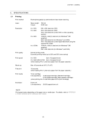
...APPENDIX 3 'PRINT SPEEDS WITH VARIOUS SETTINGS'. 1-5 CHAPTER 1 GENERAL 3. SPECIFICATIONS 3.1 Printing Print method Electrophotography by semiconductor laser beam scanning Laser Wave length: 780 nm Output: 5mW max Resolution HL-1030: HL-1240: HL-1250: HL-1270N: 600 x 600 dots/inch (GDI) 600 x 600 dots/inch (GDI) 300 x 300 dots/inch (... cartridge) 6,000 pages/cartridge (High-capacity cartridge) (when printing A4 or Letter-size paper at 5% print coverage) Developer Drum unit Life expectancy: 20,000 pages/drum unit *NOTE: Print speed varies depending on the paper size or media type.
...APPENDIX 3 'PRINT SPEEDS WITH VARIOUS SETTINGS'. 1-5 CHAPTER 1 GENERAL 3. SPECIFICATIONS 3.1 Printing Print method Electrophotography by semiconductor laser beam scanning Laser Wave length: 780 nm Output: 5mW max Resolution HL-1030: HL-1240: HL-1250: HL-1270N: 600 x 600 dots/inch (GDI) 600 x 600 dots/inch (GDI) 300 x 300 dots/inch (... cartridge) 6,000 pages/cartridge (High-capacity cartridge) (when printing A4 or Letter-size paper at 5% print coverage) Developer Drum unit Life expectancy: 20,000 pages/drum unit *NOTE: Print speed varies depending on the paper size or media type.

Service Manual
Page 19
Approx. 12.7 kg (27.9 lb.) including the drum unit and Lower Tray unit. *NOTE: • The peak figure of power ... excluding inrush current value. • The peak figure of power consumption is a reference value and should be used internally at Brother offices only. • The power consumption figure quoted for sleep mode is when the fan has stopped. 1-7 and...): Standing by: Sleep*: 940 W or less 340 W or less 80 W or less 5 W or less (HL-1030/1240) 6 W or less (HL-1250) 12W or less (HL-1270N) Noise Printing: 49 dB A or less Standing by: 27 dB A or less Temperature Operating: 10 to ...
Approx. 12.7 kg (27.9 lb.) including the drum unit and Lower Tray unit. *NOTE: • The peak figure of power ... excluding inrush current value. • The peak figure of power consumption is a reference value and should be used internally at Brother offices only. • The power consumption figure quoted for sleep mode is when the fan has stopped. 1-7 and...): Standing by: Sleep*: 940 W or less 340 W or less 80 W or less 5 W or less (HL-1030/1240) 6 W or less (HL-1250) 12W or less (HL-1270N) Noise Printing: 49 dB A or less Standing by: 27 dB A or less Temperature Operating: 10 to ...

Service Manual
Page 21
... on the back of pre-printed paper, if the paper is recommended to use long-grained paper for use in laser printers. • Avoid feeding labels with the carrier sheet exposed, or the printer will be damaged. • Before loading paper with holes such as vinyl coated paper. • Avoid using coated ... paper cassette to avoid any paper jams or misfeeds. 1-9 If short-grained paper is recommended to use acid paper to avoid any damage to the drum unit. • Avoid using preprinted or highly textured paper. • It is being used might be sure to fan the stack well. • Do ...
... on the back of pre-printed paper, if the paper is recommended to use long-grained paper for use in laser printers. • Avoid feeding labels with the carrier sheet exposed, or the printer will be damaged. • Before loading paper with holes such as vinyl coated paper. • Avoid using coated ... paper cassette to avoid any paper jams or misfeeds. 1-9 If short-grained paper is recommended to use acid paper to avoid any damage to the drum unit. • Avoid using preprinted or highly textured paper. • It is being used might be sure to fan the stack well. • Do ...

Service Manual
Page 26
AC cord 2-2 UNPACKING When unpacking the printer, check to see that all of the following components are included in the carton. Printer Paper cassette Drum unit (with Toner cartridge included) Documents CD-ROM Floppy disk Fig. 2-1 NOTE: Components may vary depending on the country. CHAPTER 2 INSTALLATION AND BASIC OPERATION 2.
AC cord 2-2 UNPACKING When unpacking the printer, check to see that all of the following components are included in the carton. Printer Paper cassette Drum unit (with Toner cartridge included) Documents CD-ROM Floppy disk Fig. 2-1 NOTE: Components may vary depending on the country. CHAPTER 2 INSTALLATION AND BASIC OPERATION 2.
Service Manual
Page 29
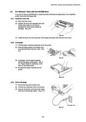
...CD-ROM Drive If you do not have a CD-ROM drive, setup the printer following the steps below, then install the printer driver from the floppy disk. 3.2.1 Install the drum unit (1) Open the front cover. (2) Unpack the drum unit assembly and rock it from side to side 5 or 6 times to distribute... the toner evenly inside the cartridge. (Fig. 2-8) Fig. 2-8 (3) Install the drum unit into the printer until it snaps into place and close the front cover. 3.2.2 Load paper (1) Pull the paper cassette completely out of the printer. (2) Slide the paper guides to the paper size you want until they snap into...
...CD-ROM Drive If you do not have a CD-ROM drive, setup the printer following the steps below, then install the printer driver from the floppy disk. 3.2.1 Install the drum unit (1) Open the front cover. (2) Unpack the drum unit assembly and rock it from side to side 5 or 6 times to distribute... the toner evenly inside the cartridge. (Fig. 2-8) Fig. 2-8 (3) Install the drum unit into the printer until it snaps into place and close the front cover. 3.2.2 Load paper (1) Pull the paper cassette completely out of the printer. (2) Slide the paper guides to the paper size you want until they snap into...

Service Manual
Page 37
...a button on the control panel. The printer is ready to indicate a paper error. See Subsection 2.1 'Operator Calls' in the printer and press the panel button. ON The printer is cooling down and stops printing until the internal temperature of the printer. They blink simultaneously to print. Misfeed Re...-install the paper and press the panel button. 2-13 LED Printer status OFF The power switch is off, or the printer is in sleep mode, it will wake up . LEDs Drum Ready Paper ...
...a button on the control panel. The printer is ready to indicate a paper error. See Subsection 2.1 'Operator Calls' in the printer and press the panel button. ON The printer is cooling down and stops printing until the internal temperature of the printer. They blink simultaneously to print. Misfeed Re...-install the paper and press the panel button. 2-13 LED Printer status OFF The power switch is off, or the printer is in sleep mode, it will wake up . LEDs Drum Ready Paper ...

Service Manual
Page 38
... Alarm LED with a new one . 5.4 Alarm LED Indications The Alarm LED blinks (with no print data. Purchase a new toner cartridge ready for details. LED Printer status OFF The drum unit can be used. Refer to indicate a toner error. They blink simultaneously to Subsection 2.2 'Service Calls' in CHAPTER 6 for when the 'Toner empty...
... Alarm LED with a new one . 5.4 Alarm LED Indications The Alarm LED blinks (with no print data. Purchase a new toner cartridge ready for details. LED Printer status OFF The drum unit can be used. Refer to indicate a toner error. They blink simultaneously to Subsection 2.2 'Service Calls' in CHAPTER 6 for when the 'Toner empty...

Service Manual
Page 43
... of the HL-1030/1240 printer. CHAPTER 3 THEORY OF OPERATION CHAPTER3 THEORY OF OPERATION 1. Control system RAM 2MB Video control block Interface block (HL-1030: Parallel) (HL1240: Parallel/USB) External device Low-voltage power supply block High-voltage power supply block Engine control block Operation block (Control panel) Laser unit Drive block (DC motor) Drum unit Transfer...
... of the HL-1030/1240 printer. CHAPTER 3 THEORY OF OPERATION CHAPTER3 THEORY OF OPERATION 1. Control system RAM 2MB Video control block Interface block (HL-1030: Parallel) (HL1240: Parallel/USB) External device Low-voltage power supply block High-voltage power supply block Engine control block Operation block (Control panel) Laser unit Drive block (DC motor) Drum unit Transfer...

Service Manual
Page 44
... printer. RS-232C) Expansion I /F board (Mac. External device Optional RAM (SIMM) (max. 32Mbytes) Control system RAM 4MB Expansion memory I/O Optional I /O Video control block Interface block (Parallel / USB) External device Low-voltage power supply block High-voltage power supply block Engine control block Operation block (Control panel) Laser unit Drive block (DC motor) Drum...
... printer. RS-232C) Expansion I /F board (Mac. External device Optional RAM (SIMM) (max. 32Mbytes) Control system RAM 4MB Expansion memory I/O Optional I /O Video control block Interface block (Parallel / USB) External device Low-voltage power supply block High-voltage power supply block Engine control block Operation block (Control panel) Laser unit Drive block (DC motor) Drum...

Service Manual
Page 45
... / USB) External device Low-voltage power supply block High-voltage power supply block Engine control block Operation block (Control panel) Laser unit Drive block (DC motor) Drum unit Transfer block Charging block Drum Paper dust cleaner block Developing block Toner cartridge Image generation system Paper tray unit Paper cassette Manual feed Fixing unit...
... / USB) External device Low-voltage power supply block High-voltage power supply block Engine control block Operation block (Control panel) Laser unit Drive block (DC motor) Drum unit Transfer block Charging block Drum Paper dust cleaner block Developing block Toner cartridge Image generation system Paper tray unit Paper cassette Manual feed Fixing unit...

Service Manual
Page 62
For the circuit diagram of the high-voltage power supply PCB, see Appendix 22. CHAPTER 3 THEORY OF OPERATION 1.6.2 High-voltage power supply The high-voltage power supply generates and outputs the voltages and currents for the charging, development and transfer functions. R1 24VI GND Current Regulator B1 Voltage Regulator VR22 Current Regulator B102 Q81 Voltage Regulator B101 Q101 Voltage Regulator Z51 VR51 Supply Roller Transfer Roller Development Roller Photosensitive Drum Corona Unit Fig. 3-26 3-20
For the circuit diagram of the high-voltage power supply PCB, see Appendix 22. CHAPTER 3 THEORY OF OPERATION 1.6.2 High-voltage power supply The high-voltage power supply generates and outputs the voltages and currents for the charging, development and transfer functions. R1 24VI GND Current Regulator B1 Voltage Regulator VR22 Current Regulator B102 Q81 Voltage Regulator B101 Q101 Voltage Regulator Z51 VR51 Supply Roller Transfer Roller Development Roller Photosensitive Drum Corona Unit Fig. 3-26 3-20

Service Manual
Page 63
MECHANICS 2.1 Overview of Printing Mechanism Second eject roller Photosensitive drum Thermistor Cleaner Corona wire Laser Unit Polygon mirror Scanner motor Rear cover Heat roller First eject roller Drum Unit Development roller Blade Agitator Toner sensor Supply roller Paper feed roller Fixing Unit Eject sensor lever Pressure roller Transfer roller Paper pick-up roller Cassette pressure roller Separation pad Paper Pressure plate Paper Cassette Rear registration sensor lever Fig. 3-27 Front registration sensor lever 3-21 CHAPTER 3 THEORY OF OPERATION 2.
MECHANICS 2.1 Overview of Printing Mechanism Second eject roller Photosensitive drum Thermistor Cleaner Corona wire Laser Unit Polygon mirror Scanner motor Rear cover Heat roller First eject roller Drum Unit Development roller Blade Agitator Toner sensor Supply roller Paper feed roller Fixing Unit Eject sensor lever Pressure roller Transfer roller Paper pick-up roller Cassette pressure roller Separation pad Paper Pressure plate Paper Cassette Rear registration sensor lever Fig. 3-27 Front registration sensor lever 3-21 CHAPTER 3 THEORY OF OPERATION 2.

Service Manual
Page 64
... Low-Voltage Power Supply PCB Fixing Unit Halogen Heater Lamp Laser Unit Laser Polygon Motor Engine PCB Front Registration Sensor Rear Registration Sensor Upper Paper Cassette Sensor (HL-1250/1270N) Lower Paper Cassette Registration Sensor (HL-1250/1270N) HighVoltage Power Supply PCB Cover Sensor (B) Drum Unit Primary Charger (Corona Wire) Primary Charger (Grid) Development Roller...
... Low-Voltage Power Supply PCB Fixing Unit Halogen Heater Lamp Laser Unit Laser Polygon Motor Engine PCB Front Registration Sensor Rear Registration Sensor Upper Paper Cassette Sensor (HL-1250/1270N) Lower Paper Cassette Registration Sensor (HL-1250/1270N) HighVoltage Power Supply PCB Cover Sensor (B) Drum Unit Primary Charger (Corona Wire) Primary Charger (Grid) Development Roller...


