

Instruction Manual - English
Page 1
DIRECT DRIVE PROGRAMMABLE ELECTRONIC PATTERN SEWER Please keep this manual before using the machine. BAS-342G INSTRUCTION MANUAL Please read this manual within easy reach for quick reference.
DIRECT DRIVE PROGRAMMABLE ELECTRONIC PATTERN SEWER Please keep this manual before using the machine. BAS-342G INSTRUCTION MANUAL Please read this manual within easy reach for quick reference.
Instruction Manual - English
Page 2
BAS-342G Follow the instructions from training personnel and instructors regarding safe and correct operation before operating the machine so that can be caused by these parts. Thank you will know how to use it is normal to carry out work while positioned directly in the instruction manual. With industrial sewing... machines, it correctly. Before using your new machine, please read the safety instructions below and the explanations given in front of moving parts such as the needle...
BAS-342G Follow the instructions from training personnel and instructors regarding safe and correct operation before operating the machine so that can be caused by these parts. Thank you will know how to use it is normal to carry out work while positioned directly in the instruction manual. With industrial sewing... machines, it correctly. Before using your new machine, please read the safety instructions below and the explanations given in front of moving parts such as the needle...
Instruction Manual - English
Page 3
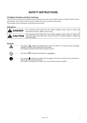
... the symbol at left means "beware of injury".) This symbol ( ) indicates something that you must make the ground connection".) BAS-342G i The meanings of these indications and symbols are provided in death or serious injury. The picture inside the circle indicates the ...that you must do . SAFETY INSTRUCTIONS [1] Safety indications and their meanings This instruction manual and the indications and symbols that are used on the machine itself are given below. Indications DANGER The instructions which follow the instructions will result in order to ensure safe...
... the symbol at left means "beware of injury".) This symbol ( ) indicates something that you must make the ground connection".) BAS-342G i The meanings of these indications and symbols are provided in death or serious injury. The picture inside the circle indicates the ...that you must do . SAFETY INSTRUCTIONS [1] Safety indications and their meanings This instruction manual and the indications and symbols that are used on the machine itself are given below. Indications DANGER The instructions which follow the instructions will result in order to ensure safe...
Instruction Manual - English
Page 4
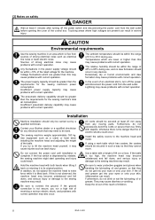
... that they cannot move. Furthermore, do not get into your eyes or onto your Brother dealer or a qualified electrician for the sewing machine's power consumption. Sources of strong ...humid environments and dew formation may cause problems with correct operation. Contact your skin. Use equipment such as electrical line noise or static electric noise. All cords should be ...the height of the rated voltage for the sewing machine's total air consumption. ii BAS-342G Insufficient power supply capacity may cause problems with correct operation. The pneumatic delivery capability...
... that they cannot move. Furthermore, do not get into your eyes or onto your Brother dealer or a qualified electrician for the sewing machine's power consumption. Sources of strong ...humid environments and dew formation may cause problems with correct operation. Contact your skin. Use equipment such as electrical line noise or static electric noise. All cords should be ...the height of the rated voltage for the sewing machine's total air consumption. ii BAS-342G Insufficient power supply capacity may cause problems with correct operation. The pneumatic delivery capability...
Instruction Manual - English
Page 5
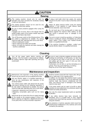
... the reach of any maintenance and inspection of the broken needle may enter your Brother dealer or a qualified electrician to wear protective goggles when using the sewing machine. Use only the proper replacement parts as specified by a qualified technician. BAS-342G iii Cleaning Turn off the power switch at the following operations. If this may...
... the reach of any maintenance and inspection of the broken needle may enter your Brother dealer or a qualified electrician to wear protective goggles when using the sewing machine. Use only the proper replacement parts as specified by a qualified technician. BAS-342G iii Cleaning Turn off the power switch at the following operations. If this may...
Instruction Manual - English
Page 6
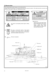
[3] Warning labels The following warning labels appear on the labels at all times when using the machine. cover, X motor cover, tension release solenoid cover, inside cover, outside cover, middle cover, fixed cover and rear cover 4 Be sure to avoid getting... take -up cover Eye guard Rear cover Inside cover R Middle cover Outside cover Finger guard iv BAS-342G Fixed cover 3956M If the labels have been removed or are difficult to read, please contact your nearest Brother dealer. 1 2 Safety devices: Devices such as eye guard, finger 3 Be careful to connect the ground. ...
[3] Warning labels The following warning labels appear on the labels at all times when using the machine. cover, X motor cover, tension release solenoid cover, inside cover, outside cover, middle cover, fixed cover and rear cover 4 Be sure to avoid getting... take -up cover Eye guard Rear cover Inside cover R Middle cover Outside cover Finger guard iv BAS-342G Fixed cover 3956M If the labels have been removed or are difficult to read, please contact your nearest Brother dealer. 1 2 Safety devices: Devices such as eye guard, finger 3 Be careful to connect the ground. ...
Instruction Manual - English
Page 8
...pattern 31 6-7. Tilting back and returning the machine head ... 7 4-6. Adjusting the speed controller [7 11 4-13. Installing the bobbin case 23 5-6. Using cycle programs 42 7-9. Using user programs 39 7-8. Connecting the air tubes [4 10 4-10. Installing the needle 19 5-2. Removing the machine head fixing bolts [1] .... 4 ...4-2. List of each operation panel item 27 6-2. Installing the eye guard [11 16 4-17. Setting the program number 29 6-4. USING THE OPERATION PANEL (ADVANCED OPERATIONS 33 7-1. Writing all sewing data from the CF card at once 50 BAS-342G
...pattern 31 6-7. Tilting back and returning the machine head ... 7 4-6. Adjusting the speed controller [7 11 4-13. Installing the bobbin case 23 5-6. Using cycle programs 42 7-9. Using user programs 39 7-8. Connecting the air tubes [4 10 4-10. Installing the needle 19 5-2. Removing the machine head fixing bolts [1] .... 4 ...4-2. List of each operation panel item 27 6-2. Installing the eye guard [11 16 4-17. Setting the program number 29 6-4. USING THE OPERATION PANEL (ADVANCED OPERATIONS 33 7-1. Writing all sewing data from the CF card at once 50 BAS-342G
Instruction Manual - English
Page 9
... installation position 63 11-13. Adjusting the air pressure 65 12. Checking the needle 54 10-7. Adjusting the needle bar height 56 11-4. Using the STOP switch 52 9-3. Cleaning the eye guard 54 10-6. Adjusting the needle clearance 57 11-7. Adjusting the position of the movable knife ... Adjusting the thread wiper 62 11-12. Replacing the movable and fixed knives...... 61 11-10-1. TROUBLESHOOTING 70 14. 7-SEGMENT DISPLAY 73 BAS-342G Cleaning the control box air inlet ports 54 10-5. Adjusting the thread take-up spring 55 11-2. TABLE OF ERROR CODES 66 13. ...
... installation position 63 11-13. Adjusting the air pressure 65 12. Checking the needle 54 10-7. Adjusting the needle bar height 56 11-4. Using the STOP switch 52 9-3. Cleaning the eye guard 54 10-6. Adjusting the needle clearance 57 11-7. Adjusting the position of the movable knife ... Adjusting the thread wiper 62 11-12. Replacing the movable and fixed knives...... 61 11-10-1. TROUBLESHOOTING 70 14. 7-SEGMENT DISPLAY 73 BAS-342G Cleaning the control box air inlet ports 54 10-5. Adjusting the thread take-up spring 55 11-2. TABLE OF ERROR CODES 66 13. ...

Instruction Manual - English
Page 12
If the control box and the leg are too close together, it should be strong enough to bear the weight and vibration of the sewing machine. • If using casters, use ones which can bear the total weight of the table should be at least 50 mm, and it may result in incorrect sewing machine operation. 4053M 3 BAS-342G TABLE PROCESSING DIAGRAM • The thickness of sewing machine and table. • Check that the control box is at least 10 mm away from the leg. TABLE PROCESSING DIAGRAM 3. 3.
If the control box and the leg are too close together, it should be strong enough to bear the weight and vibration of the sewing machine. • If using casters, use ones which can bear the total weight of the table should be at least 50 mm, and it may result in incorrect sewing machine operation. 4053M 3 BAS-342G TABLE PROCESSING DIAGRAM • The thickness of sewing machine and table. • Check that the control box is at least 10 mm away from the leg. TABLE PROCESSING DIAGRAM 3. 3.
Instruction Manual - English
Page 13
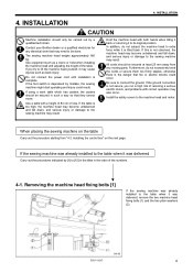
..., remove the two machine head fixing bolts (1) and the two plain washers (2). 3960M BAS-342G 4 INSTALLATION CAUTION Machine installation should only be secured at least 25 mm away from "4-2. If using a work that they cannot move. If this is depressed by a qualified technician. Furthermore... not secure, you try to its original position. If the ground connection is complete. Contact your Brother dealer or a qualified electrician for any moving parts. Use equipment such as back injury. When placing the sewing machine on the next page. INSTALLATION 4. 4.
..., remove the two machine head fixing bolts (1) and the two plain washers (2). 3960M BAS-342G 4 INSTALLATION CAUTION Machine installation should only be secured at least 25 mm away from "4-2. If using a work that they cannot move. If this is depressed by a qualified technician. Furthermore... not secure, you try to its original position. If the ground connection is complete. Contact your Brother dealer or a qualified electrician for any moving parts. Use equipment such as back injury. When placing the sewing machine on the next page. INSTALLATION 4. 4.

Instruction Manual - English
Page 15
... pcs.] 3964M 4-4. Do not let any cords get clamped between the machine head and the table. ! Installing the machine head Table 1. NOTE: • Use a crane or hoist to install the sewing machine. • Be careful of the oil pan (a) or the support lever base (b). ! Do not place ... the support lever base (b). (1) Rubber bushes (2 pcs.) (2) Hinge holders (2 pcs.) (3) Plain washers [4 pcs.] (4) Spring washers [4 pcs.] (5) Bolts [4 pcs.] 3965M BAS-342G (Continued on top of the following when lowering the machine head onto the table. ! 4-3. Place the machine head onto the table.
... pcs.] 3964M 4-4. Do not let any cords get clamped between the machine head and the table. ! Installing the machine head Table 1. NOTE: • Use a crane or hoist to install the sewing machine. • Be careful of the oil pan (a) or the support lever base (b). ! Do not place ... the support lever base (b). (1) Rubber bushes (2 pcs.) (2) Hinge holders (2 pcs.) (3) Plain washers [4 pcs.] (4) Spring washers [4 pcs.] (5) Bolts [4 pcs.] 3965M BAS-342G (Continued on top of the following when lowering the machine head onto the table. ! 4-3. Place the machine head onto the table.
Instruction Manual - English
Page 17
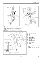
Tilting back and returning the machine head".) Note that the L and R shapes are different. 3969M BAS-342G 8 Tighten the two set screws (2) to "4-5. Install the gas spring (8). (4) Gas spring holders [L and R] (5) Spacer (6) Bolt (7) Nut (8) Gas spring (9) Shaft collars [2 pcs.] (10) Gas spring ... machine head. 2. 4-6. Installing the gas spring Crane or hoist 4. INSTALLATION Engaging the stopper Disengaging the stopper 3968M 1. Tilting back and returning the machine head".) NOTE: Use equipment such as a crane or hoist to "4-5.
Tilting back and returning the machine head".) Note that the L and R shapes are different. 3969M BAS-342G 8 Tighten the two set screws (2) to "4-5. Install the gas spring (8). (4) Gas spring holders [L and R] (5) Spacer (6) Bolt (7) Nut (8) Gas spring (9) Shaft collars [2 pcs.] (10) Gas spring ... machine head. 2. 4-6. Installing the gas spring Crane or hoist 4. INSTALLATION Engaging the stopper Disengaging the stopper 3968M 1. Tilting back and returning the machine head".) NOTE: Use equipment such as a crane or hoist to "4-5.

Instruction Manual - English
Page 20
...• When the lower knob is tightened, the lifting speed becomes slower. Adjusting the speed controller [7] You can operate the work clamp using the knobs on the valves. • When the upper knob is tightened, the lowering speed becomes slower. Adjusting the air pressure [6] Lift... (2) of the regulator (1) and then turn it . 3975M 4-12. After adjustment is turned off by pressing the manual buttons (1). 3976M 11 BAS-342G Upper knob Lower knob Valve 2 Reference adjustments Valve 1 Upper knob Lower knob Valve 2 Upper knob Lower knob Fully tighten Fully tighten and then ...
...• When the lower knob is tightened, the lifting speed becomes slower. Adjusting the speed controller [7] You can operate the work clamp using the knobs on the valves. • When the upper knob is tightened, the lowering speed becomes slower. Adjusting the air pressure [6] Lift... (2) of the regulator (1) and then turn it . 3975M 4-12. After adjustment is turned off by pressing the manual buttons (1). 3976M 11 BAS-342G Upper knob Lower knob Valve 2 Reference adjustments Valve 1 Upper knob Lower knob Valve 2 Upper knob Lower knob Fully tighten Fully tighten and then ...
Instruction Manual - English
Page 25
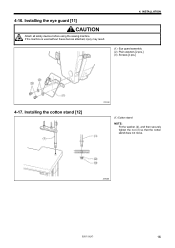
Installing the cotton stand [12] 4934Q (1) Cotton stand NOTE: Fit the washer (2), and then securely tighten the nut (3) so that the cotton stand does not move. 3983M BAS-342G 16 4-16. If the machine is used without these devices attached, injury may result. 4. INSTALLATION (1) Eye guard assembly (2) Plain washers [2 pcs.] (3) Screws [2 pcs.] 4-17. Installing the eye guard [11] CAUTION Attach all safety devices before using the sewing machine.
Installing the cotton stand [12] 4934Q (1) Cotton stand NOTE: Fit the washer (2), and then securely tighten the nut (3) so that the cotton stand does not move. 3983M BAS-342G 16 4-16. If the machine is used without these devices attached, injury may result. 4. INSTALLATION (1) Eye guard assembly (2) Plain washers [2 pcs.] (3) Screws [2 pcs.] 4-17. Installing the eye guard [11] CAUTION Attach all safety devices before using the sewing machine.
Instruction Manual - English
Page 26
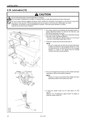
...so that they do not drink or eat the lubricating oil or grease. If using the needle cooler (3).) BAS-342G Threading the upper thread" for the first time, and also after long periods of non-use. • Use only the lubricating oil specified by mistake, the sewing machine might start operating ... no more oil when the oil level drops down to "5-3. Lubrication [13] CAUTION Do not connect the power cord until lubrication is depressed by Brother. * If this type of children. • The sewing machine should always be lubricated and the oil supply replenished before it with silicon oil...
...so that they do not drink or eat the lubricating oil or grease. If using the needle cooler (3).) BAS-342G Threading the upper thread" for the first time, and also after long periods of non-use. • Use only the lubricating oil specified by mistake, the sewing machine might start operating ... no more oil when the oil level drops down to "5-3. Lubrication [13] CAUTION Do not connect the power cord until lubrication is depressed by Brother. * If this type of children. • The sewing machine should always be lubricated and the oil supply replenished before it with silicon oil...
Instruction Manual - English
Page 27
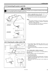
...power supply. * The inside of the safety switch (1). 1. Checking the safety switch [15] 1. Check the installation position of the control box uses single-phase power. Push down the right side of receiving a serious electric shock, and problems with correct operation. Turn on , and then ...it may cause problems with correct operation may occur. • Do not use an extension cord. Loosen the two screws (2). 3. Turn off the power switch. 2. Check that no error numbers are displayed. 3989M BAS-342G 18 boards may also occur. 1. If the machine head is not ...
...power supply. * The inside of the safety switch (1). 1. Checking the safety switch [15] 1. Check the installation position of the control box uses single-phase power. Push down the right side of receiving a serious electric shock, and problems with correct operation. Turn on , and then ...it may cause problems with correct operation may occur. • Do not use an extension cord. Loosen the two screws (2). 3. Turn off the power switch. 2. Check that no error numbers are displayed. 3989M BAS-342G 18 boards may also occur. 1. If the machine head is not ...

Instruction Manual - English
Page 28
... mistake, the sewing machine might start switch (right side) is then depressed, the sewing machine starts operating. * The work clamp (2) lowering method can be changed using memory switch No. 002. (Refer to "7-3. 5. PREPARATION BEFORE SEWING 5. Loosen the set screw (1). 3990M 5-2. Insert the needle (2) in a straight line as far as it will... Start switch 3991M When the work clamp (2) are lowered, and when the start operating and injury could result. 1. List of memory switch settings.") 3992M 19 BAS-342G PREPARATION BEFORE SEWING 5-1.
... mistake, the sewing machine might start switch (right side) is then depressed, the sewing machine starts operating. * The work clamp (2) lowering method can be changed using memory switch No. 002. (Refer to "7-3. 5. PREPARATION BEFORE SEWING 5. Loosen the set screw (1). 3990M 5-2. Insert the needle (2) in a straight line as far as it will... Start switch 3991M When the work clamp (2) are lowered, and when the start operating and injury could result. 1. List of memory switch settings.") 3992M 19 BAS-342G PREPARATION BEFORE SEWING 5-1.
Instruction Manual - English
Page 29
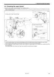
BAS-342G 20 PREPARATION BEFORE SEWING 5-3. If the trailing length of the thread. 5. Threading the upper thread Thread the upper thread correctly as shown in the illustration below. * When using threading mode for threading, the tension discs (1) will open so that the thread can be threaded more easily.... (Refer to following page.) 3994M [If using cotton thread or spun thread] [If using synthetic thread] Thread the upper thread Needle cooler 3993M 3995M • Turn the machine pulley (2) and raise the thread...
BAS-342G 20 PREPARATION BEFORE SEWING 5-3. If the trailing length of the thread. 5. Threading the upper thread Thread the upper thread correctly as shown in the illustration below. * When using threading mode for threading, the tension discs (1) will open so that the thread can be threaded more easily.... (Refer to following page.) 3994M [If using cotton thread or spun thread] [If using synthetic thread] Thread the upper thread Needle cooler 3993M 3995M • Turn the machine pulley (2) and raise the thread...

Instruction Manual - English
Page 33
... 1. Lower thread tension Stronger Weaker Adjust the thread tension to adjust the tension as appropriate for the material being sewn. 2. Stronger Weaker Stronger Weaker 4003M BAS-342G 24 Use the tension nut (2) (sub tension) to adjust the upper thread trailing length to about 42 mm. PREPARATION BEFORE SEWING 5-6-1.
... 1. Lower thread tension Stronger Weaker Adjust the thread tension to adjust the tension as appropriate for the material being sewn. 2. Stronger Weaker Stronger Weaker 4003M BAS-342G 24 Use the tension nut (2) (sub tension) to adjust the upper thread trailing length to about 42 mm. PREPARATION BEFORE SEWING 5-6-1.

Instruction Manual - English
Page 36
... mode or work clamp height setting mode. (7) THREAD/CLAMP indicator Illuminates when the THREAD/CLAMP key (6) has been pressed. (8) TENSION/WIND key Used to wind the lower thread. (9) TENSION/WIND indicator Used when the digital tension set (option) is installed. 27 BAS-342G 4435Q USING THE OPERATION PANEL (BASIC OPERATIONS) 6-1. USING THE OPERATION PANEL (BASIC OPERATIONS) 6.
... mode or work clamp height setting mode. (7) THREAD/CLAMP indicator Illuminates when the THREAD/CLAMP key (6) has been pressed. (8) TENSION/WIND key Used to wind the lower thread. (9) TENSION/WIND indicator Used when the digital tension set (option) is installed. 27 BAS-342G 4435Q USING THE OPERATION PANEL (BASIC OPERATIONS) 6-1. USING THE OPERATION PANEL (BASIC OPERATIONS) 6.


