

Hand Book - English
Page 1
...,000 stitches per pattern (max. 100 patterns, 360,000 stitches / 2HD floppy disk) DP × 5, DP × 17, MR 0.05 mm Operation test function provided for use with low speed drive Automatic stop function for activation in the event of work clamp Stepping presser foot lift stroke No. Y Max. number of stitches Feed mechanism Height of misoperation realized with Cylinder Bed Specifications Machine head Application Sewing speed Stitch length Sewing area X - BAS-311E 311EL...
...,000 stitches per pattern (max. 100 patterns, 360,000 stitches / 2HD floppy disk) DP × 5, DP × 17, MR 0.05 mm Operation test function provided for use with low speed drive Automatic stop function for activation in the event of work clamp Stepping presser foot lift stroke No. Y Max. number of stitches Feed mechanism Height of misoperation realized with Cylinder Bed Specifications Machine head Application Sewing speed Stitch length Sewing area X - BAS-311E 311EL...

Programmer Instruction Manual - English
Page 2
Operation of this machine correctly. Please follow the operational and safety instructions by the experts/instructors and use this industrial sewing machine is usually carried out in front of moving parts such as the needle and the needle thread take-up. Please read this "Programmer Instruction Manual" and the separate volume "Programmable Electronic Pattern Sewer Instruction Manual" carefully before using the machine. These parts may cause personal injuries. Thank you very much for purchasing the Brother Industrial Sewing Machine. Programmer 1
Operation of this machine correctly. Please follow the operational and safety instructions by the experts/instructors and use this industrial sewing machine is usually carried out in front of moving parts such as the needle and the needle thread take-up. Please read this "Programmer Instruction Manual" and the separate volume "Programmable Electronic Pattern Sewer Instruction Manual" carefully before using the machine. These parts may cause personal injuries. Thank you very much for purchasing the Brother Industrial Sewing Machine. Programmer 1

Extended Option Output Instruction Manual - English
Page 6
...the assumption that was set in 2-3 remains. ƒAfter overwriting the option program to the FD, press the P key to the condition number table of standard output (see page 100 of the trigger data and descends at sewing start. 2-5 Outputting in... the following 2-6. •Prepare the programmer, and display the output setting screen. ,Referring to turn off and on the setting screen as follows: ...Put the sewing data in memory by a new program No.after inputting the trigger data. Check that the left work clamp rises at a position of the instruction manual...
...the assumption that was set in 2-3 remains. ƒAfter overwriting the option program to the FD, press the P key to the condition number table of standard output (see page 100 of the trigger data and descends at sewing start. 2-5 Outputting in... the following 2-6. •Prepare the programmer, and display the output setting screen. ,Referring to turn off and on the setting screen as follows: ...Put the sewing data in memory by a new program No.after inputting the trigger data. Check that the left work clamp rises at a position of the instruction manual...

Extended Option Output Instruction Manual - English
Page 7
... and carry out sewing. Referring to the condition number table of machine operation mode (see page 193), set No. 15 and 16 to be convenient to 0.7 second (700ms). Check that turns ON first, and it will be ON and OFF at down position. ƒReferring to the condition number table of the programmer, and then turn the power off and...
... and carry out sewing. Referring to the condition number table of machine operation mode (see page 193), set No. 15 and 16 to be convenient to 0.7 second (700ms). Check that turns ON first, and it will be ON and OFF at down position. ƒReferring to the condition number table of the programmer, and then turn the power off and...

Network Users Manual - English
Page 3
.... The sewing machine should only be used for any electrical work table which has casters, the casters chould be done. If an error occurs in machine operation, or if abnormal noises or smells are present can result in such a way so that they can result. Do not connect the power cord until installation is complete, otherwise the machine may operate if the start switch...
.... The sewing machine should only be used for any electrical work table which has casters, the casters chould be done. If an error occurs in machine operation, or if abnormal noises or smells are present can result in such a way so that they can result. Do not connect the power cord until installation is complete, otherwise the machine may operate if the start switch...

Network Users Manual - English
Page 4
... circumstances, as they can result. If the power switch and air need to be left on the pressure gauge to drop to "0" before using the machine. Any problems in machine operation which use the pneumatic equipment. Keep the oil out of the reach of the electrical system. If any cleaning work, otherwise the machine may operate if the start switch is pressed by mistake, which could...
... circumstances, as they can result. If the power switch and air need to be left on the pressure gauge to drop to "0" before using the machine. Any problems in machine operation which use the pneumatic equipment. Keep the oil out of the reach of the electrical system. If any cleaning work, otherwise the machine may operate if the start switch is pressed by mistake, which could...
Network Users Manual - English
Page 6
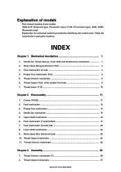
... type 23 10. Assembly 26 1. Check the model before useing the machine. Feed mechanism (X axis 4 4. Presser foot mechanism (1)(2 6 5. Thread nipper mechanism 24 11. Thread nipper mechanism 27 BAS-311E.311EL.326E.326EL Thread nipper (1)(2) when presser foot rises 9 7. Feed mechanism (X axis)(1)(2 20 8. Thread trimmer mechanism 25 Chapter 3. INDEX Chapter 1. Feed mechanism ...13 3. Upper shaft mechanism 16 6. Thread trimmer mechanism 8 6. Disassembly 11 1. Mechanical description 1 1. Needle bar, thread take-up, lower shaft and shuttle hook mechanism 1 2. Covers...
... type 23 10. Assembly 26 1. Check the model before useing the machine. Feed mechanism (X axis 4 4. Presser foot mechanism (1)(2 6 5. Thread nipper mechanism 24 11. Thread nipper mechanism 27 BAS-311E.311EL.326E.326EL Thread nipper (1)(2) when presser foot rises 9 7. Feed mechanism (X axis)(1)(2 20 8. Thread trimmer mechanism 25 Chapter 3. INDEX Chapter 1. Feed mechanism ...13 3. Upper shaft mechanism 16 6. Thread trimmer mechanism 8 6. Disassembly 11 1. Mechanical description 1 1. Needle bar, thread take-up, lower shaft and shuttle hook mechanism 1 2. Covers...
Network Users Manual - English
Page 7
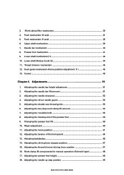
... manual operation (Solenoid type 68 17. Adjusting the needle up step position 69 BAS-311E.311EL.326E.326EL Work clamp lifter mechanism 29 4. Needle bar mechanism 40 8. Adjusting the lowest point of the timing belt 64 13. Adjusting the tension of the presser foot 58 9. 3. Upper shaft mechanism 39 7. Lower shaft (Rotary hook) (2 44 11. Wiper adjustment...60 11. Adjusting the needle bar height adjustment 51 2. Adjusting the shuttle race thread guide 52 6. Thread trimmer mechanism 45 12. Adjusting the driving lever stopper position...
... manual operation (Solenoid type 68 17. Adjusting the needle up step position 69 BAS-311E.311EL.326E.326EL Work clamp lifter mechanism 29 4. Needle bar mechanism 40 8. Adjusting the lowest point of the timing belt 64 13. Adjusting the tension of the presser foot 58 9. 3. Upper shaft mechanism 39 7. Lower shaft (Rotary hook) (2 44 11. Wiper adjustment...60 11. Adjusting the needle bar height adjustment 51 2. Adjusting the shuttle race thread guide 52 6. Thread trimmer mechanism 45 12. Adjusting the driving lever stopper position...

Network Users Manual - English
Page 8
.... Error codes ...93 Chapter 7. How to make up clamping type work clamp 70 1. Precautions at the time of adjustment 73 2. Trouble shooting 95 Flowchart ...95 Problem solution and measures 101 Chapter 8. 1. Option parts 123 Control Block diagram 140 BAS-311E.311EL.326E.326EL Power supply and electrical parts adjustment 73 1. Checking the input sensor and DIP switch input 90 8. Clearing all memory settings 91 10. How to make up the work clamp 70...
.... Error codes ...93 Chapter 7. How to make up clamping type work clamp 70 1. Precautions at the time of adjustment 73 2. Trouble shooting 95 Flowchart ...95 Problem solution and measures 101 Chapter 8. 1. Option parts 123 Control Block diagram 140 BAS-311E.311EL.326E.326EL Power supply and electrical parts adjustment 73 1. Checking the input sensor and DIP switch input 90 8. Clearing all memory settings 91 10. How to make up the work clamp 70...

Network Users Manual - English
Page 56
... turn off the power. 6. Attach the Y-sensor setting plate e to the Y-home position bracket r using the set the clearance between the Y-driving shaft y and the surface where the sensor u is too great, an error in home position detection may occur because the temperature of the H-position standard plate w. 2. Remove the needle q. 5. Replace the H-position standard plate w with the home position (X=0, Y=0) of the sewing machine rises during sewing operation. 48 BAS-311E.311EL.326E...
... turn off the power. 6. Attach the Y-sensor setting plate e to the Y-home position bracket r using the set the clearance between the Y-driving shaft y and the surface where the sensor u is too great, an error in home position detection may occur because the temperature of the H-position standard plate w. 2. Remove the needle q. 5. Replace the H-position standard plate w with the home position (X=0, Y=0) of the sewing machine rises during sewing operation. 48 BAS-311E.311EL.326E...

Network Users Manual - English
Page 70
... u is too great, an error in home position detection may occur because the temperature of the H-position standard plate r. 9. Chapter 4. Note: When adjusting the Y home position, be out of the program mode, and turn off the power. 12.Replace the H-position standard plate r with the home position (X=0, Y=0) of the sewing machine rises during sewing operation. 62 BAS-311E.311EL.326E.326EL tion standard plate r. Turn on the programmer.
... u is too great, an error in home position detection may occur because the temperature of the H-position standard plate r. 9. Chapter 4. Note: When adjusting the Y home position, be out of the program mode, and turn off the power. 12.Replace the H-position standard plate r with the home position (X=0, Y=0) of the sewing machine rises during sewing operation. 62 BAS-311E.311EL.326E.326EL tion standard plate r. Turn on the programmer.

Network Users Manual - English
Page 78
...type Work clamp (separate plate) Work clamp (single type) Cassette clamp Cassette support Feed plate Cassette clamp assembly 1. The maximum sewing range is available in two types; In the case of the sewing position. 1 - 1.5mm 1 - 1.5mm 1 - 1.5mm 70 BAS-311E.311EL.326E.326EL clamping type and cassette type. Chapter 5. How to 1.5 mm margin is wider than the sewing position by (half of the presser foot Sewing position (The needle threads along) Feed plate (Feed plate blank) D/2 + 1 to 1.5mm D/2 + 1 to 1.5mm Presser foot Work clamp 1 - 1.5mm D Feed plate Sewing position...
...type Work clamp (separate plate) Work clamp (single type) Cassette clamp Cassette support Feed plate Cassette clamp assembly 1. The maximum sewing range is available in two types; In the case of the sewing position. 1 - 1.5mm 1 - 1.5mm 1 - 1.5mm 70 BAS-311E.311EL.326E.326EL clamping type and cassette type. Chapter 5. How to 1.5 mm margin is wider than the sewing position by (half of the presser foot Sewing position (The needle threads along) Feed plate (Feed plate blank) D/2 + 1 to 1.5mm D/2 + 1 to 1.5mm Presser foot Work clamp 1 - 1.5mm D Feed plate Sewing position...
Network Users Manual - English
Page 81
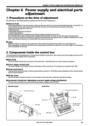
.... Operation panel Control box Panel circuit board Conversion transformer Inlee fileer 3.5 FDD DC fan Power supply circuit board Main PCB BAS-311E.311EL.326E.326EL 73 be careful not to provide 220 V. s DC fan motor The DC fan motor serves as heatsinks and covers. 2. s Injury While the power is turned off . Chapter 6 Power supply and electrical parts adjustment Chapter 6 Power supply and electrical parts adjustment...
.... Operation panel Control box Panel circuit board Conversion transformer Inlee fileer 3.5 FDD DC fan Power supply circuit board Main PCB BAS-311E.311EL.326E.326EL 73 be careful not to provide 220 V. s DC fan motor The DC fan motor serves as heatsinks and covers. 2. s Injury While the power is turned off . Chapter 6 Power supply and electrical parts adjustment Chapter 6 Power supply and electrical parts adjustment...

Network Users Manual - English
Page 95
... the final stitch, the work clamp switches. memo-0E memo-0F Test feeding is carried out at a time is available as an option.) Single-pedal operation by automatic ejector and the sewing machine automatically starts. BAS-311E.311EL.326E.326EL 87 When ON memo-20 During feed test operation, feeding 100 stitches at the same speed as normal sewing. (For checking feed operation) After sewing is finished, the work clamp is not used . (This part is available...
... the final stitch, the work clamp switches. memo-0E memo-0F Test feeding is carried out at a time is available as an option.) Single-pedal operation by automatic ejector and the sewing machine automatically starts. BAS-311E.311EL.326E.326EL 87 When ON memo-20 During feed test operation, feeding 100 stitches at the same speed as normal sewing. (For checking feed operation) After sewing is finished, the work clamp is not used . (This part is available...

Network Users Manual - English
Page 97
...) memo-34 1 - 5 ---- 0 Number of stitches sewn at 400 spm (10W speed) at sewing start point, 7: Sewing end point, 8: Upper left of mask, 9: Lower left of sewing area, 6: Sewing start memo-35 memo-36 memo-37 10 - 60 1 - 3 0 - 3 Xms ------- Solenoid ON time changes when work clamp is being 40 lowered (solenoid specifications only) 10 60 (Quiet) (High work clamp has lifted. BAS-311E.311EL.326E.326EL 89 Turn the dial while pressing the...
...) memo-34 1 - 5 ---- 0 Number of stitches sewn at 400 spm (10W speed) at sewing start point, 7: Sewing end point, 8: Upper left of mask, 9: Lower left of sewing area, 6: Sewing start memo-35 memo-36 memo-37 10 - 60 1 - 3 0 - 3 Xms ------- Solenoid ON time changes when work clamp is being 40 lowered (solenoid specifications only) 10 60 (Quiet) (High work clamp has lifted. BAS-311E.311EL.326E.326EL 89 Turn the dial while pressing the...
Network Users Manual - English
Page 101
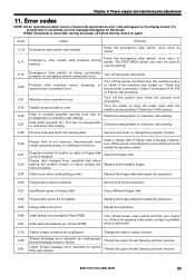
... ratio setting. Sewing can then resume. Chapter 6 Power supply and electrical parts adjustment 11. Needle up stop switch is not formatted. Floppy disk changed from readable disk when setting the bobbin thread or when setting the memory switch. Replace the floppy disk and repeat the operation. Use a different floppy disk. E.50 Floppy disk is outside possible sewing area due to enlargement or reduction ratio setting. Machine motor operation error. Replace with machine motor...
... ratio setting. Sewing can then resume. Chapter 6 Power supply and electrical parts adjustment 11. Needle up stop switch is not formatted. Floppy disk changed from readable disk when setting the bobbin thread or when setting the memory switch. Replace the floppy disk and repeat the operation. Use a different floppy disk. E.50 Floppy disk is outside possible sewing area due to enlargement or reduction ratio setting. Machine motor operation error. Replace with machine motor...

Network Users Manual - English
Page 107
... error code YES appear after the machine OFF #14 starts? YES Does the machine return to the sewing start foot switch. Step on the start position. NO Sewing Does the presser plate NO operation move stitch by stitch to turn off the TEST lamp. Input sewing data and shift to the NO sewing start and an error code OFF #13 appears? YES Are thread trimmer NO and thread wiper OFF #16 activated? YES BAS-311E...
... error code YES appear after the machine OFF #14 starts? YES Does the machine return to the sewing start foot switch. Step on the start position. NO Sewing Does the presser plate NO operation move stitch by stitch to turn off the TEST lamp. Input sewing data and shift to the NO sewing start and an error code OFF #13 appears? YES Are thread trimmer NO and thread wiper OFF #16 activated? YES BAS-311E...

Network Users Manual - English
Page 113
... the panel setting plate makes contact with a new one. With error code [E.F2], overcurrent has occurred in wiring. • Find a cause of the power PCB and connector P20 (PER) on the power PCB is securely inserted (refer to #1-7 • Pull out the programmer. Check there is securely inserted. Power PCB Panel circuit board Programmer FDD Harness Floppy disk drive BAS-311E.311EL.326E...
... the panel setting plate makes contact with a new one. With error code [E.F2], overcurrent has occurred in wiring. • Find a cause of the power PCB and connector P20 (PER) on the power PCB is securely inserted (refer to #1-7 • Pull out the programmer. Check there is securely inserted. Power PCB Panel circuit board Programmer FDD Harness Floppy disk drive BAS-311E.311EL.326E...

Network Users Manual - English
Page 119
Control circuit board defective #18 The machine can not be replaced • If the needle stop position varies at the upper position. 1. Between pins 2 and 3: ∞ Ωnormally or 0 Ω when the emergency stop switch is not resumed. • Refer to #8-1, 2, 3, 4 and #13, #14. #23 Programmi ng can not sew patterns as pro- Check/repair/adjust Parts to #8-1, 2, 3, 4. Programmer Panel circuit board BAS-311E.311EL.326E...
Control circuit board defective #18 The machine can not be replaced • If the needle stop position varies at the upper position. 1. Between pins 2 and 3: ∞ Ωnormally or 0 Ω when the emergency stop switch is not resumed. • Refer to #8-1, 2, 3, 4 and #13, #14. #23 Programmi ng can not sew patterns as pro- Check/repair/adjust Parts to #8-1, 2, 3, 4. Programmer Panel circuit board BAS-311E.311EL.326E...

Network Users Manual - English
Page 131
... device automatically replaces the bobbin. The thread wiper is no longer necessary. operates by a pneumatic cylinder. The positioning adjustment that the material can be increased. s Inner clamp device Used for perfect stitches. s Auto bobbin changer s Snap fastener and hook attachment device When the amount of bobbin thread remaining and replacing bobbins, so that the preparation for extra tools. s Needle thread presser device This allows the upper thread to the separate Parts Book for other clamps...
... device automatically replaces the bobbin. The thread wiper is no longer necessary. operates by a pneumatic cylinder. The positioning adjustment that the material can be increased. s Inner clamp device Used for perfect stitches. s Auto bobbin changer s Snap fastener and hook attachment device When the amount of bobbin thread remaining and replacing bobbins, so that the preparation for extra tools. s Needle thread presser device This allows the upper thread to the separate Parts Book for other clamps...


