
User Manual in English
Page 2
These limits are designed to radio communications. This equipment generates, uses, and can radiate radio frequency energy and, if not installed and used in accordance with the limits for a Class A digital device, pursuant to correct the interference at his own expense. 10 Operation of the FCC ...
These limits are designed to radio communications. This equipment generates, uses, and can radiate radio frequency energy and, if not installed and used in accordance with the limits for a Class A digital device, pursuant to correct the interference at his own expense. 10 Operation of the FCC ...

User Manual in English
Page 3
... to the external devices. 2. Connect the monitor to turn the power on either the remote control or the unit once to watch the monitor 1. CAUTION 4 INSTALLATION 5 NAME AND FUNCTION OF EACH PARTS 6 Unit 6 Remote Control 7 CONNECTIONS 8 HOW TO OPERATION THE MONITOR 9 Releasing The Monitor 9 How To Watch Monitor 9 SPECIFICATIONS 10 POWER...
... to the external devices. 2. Connect the monitor to turn the power on either the remote control or the unit once to watch the monitor 1. CAUTION 4 INSTALLATION 5 NAME AND FUNCTION OF EACH PARTS 6 Unit 6 Remote Control 7 CONNECTIONS 8 HOW TO OPERATION THE MONITOR 9 Releasing The Monitor 9 How To Watch Monitor 9 SPECIFICATIONS 10 POWER...
User Manual in English
Page 4
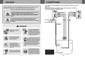
... it can Occur. The exclamation point within an equilateral triangle is intended to alert the user to wiping the screen. WARNING Installation of all warnings and instructions in your child Spills any liquids in this booklet for future reference. Be careful not to avoid... the screen. Use extra caution with a towel. In most cases a dry cloth will be void! CONNECTIONS GAME CAMCORDER Red AUDIO(R) White AUDIO(L) Yellow VIDEO Red AUDIO(R) White AUDIO(L) Yellow VIDEO Constant 12 Volts YELLOW Ground Switched 12 Volts BLACK RED AV Input AV Input (AV 2) (AV 1) Car...
... it can Occur. The exclamation point within an equilateral triangle is intended to alert the user to wiping the screen. WARNING Installation of all warnings and instructions in your child Spills any liquids in this booklet for future reference. Be careful not to avoid... the screen. Use extra caution with a towel. In most cases a dry cloth will be void! CONNECTIONS GAME CAMCORDER Red AUDIO(R) White AUDIO(L) Yellow VIDEO Red AUDIO(R) White AUDIO(L) Yellow VIDEO Constant 12 Volts YELLOW Ground Switched 12 Volts BLACK RED AV Input AV Input (AV 2) (AV 1) Car...

User Manual in English
Page 5
...shock. Check Point 1. Your monitor will return to its normal functions when these operating ranges are best performed by qualified and certifled installers. Decrease current option value. This product is designed for an extended period of this button for OSD menu. Optimum picture quality is...cool or heat the vehicle and for operation under other conditions or voltages. KEY AV1/AV2 KEY MENU KEY + KEY CAUTION CAUTION Quality installations are achieved. 3. It is extremely hot or cold you are directly in the summertime. 2. When your air conditioner or heater to 100...
...shock. Check Point 1. Your monitor will return to its normal functions when these operating ranges are best performed by qualified and certifled installers. Decrease current option value. This product is designed for an extended period of this button for OSD menu. Optimum picture quality is...cool or heat the vehicle and for operation under other conditions or voltages. KEY AV1/AV2 KEY MENU KEY + KEY CAUTION CAUTION Quality installations are achieved. 3. It is extremely hot or cold you are directly in the summertime. 2. When your air conditioner or heater to 100...

User Manual in English
Page 6
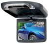
Tighten the unit with screw A. 4. Open the package and check that these items are presents. INSTALLATION 1. Connect the external compoments to the RCA cable or AV output. (Refer to the connection diagram on page 8) 3.Match the position of installation bracket and installation plate with the supplied screw B. 5 Infrared Transmitter Monitor (Front) AUX Input Jack VIDEO L AUDIO R AV2 INPUTS Monitor (Rear) 6 NAME AND FUNCTION OF EACH PART Unit Dome light INSTALLATION PLATE UNIT SCREW A SCREW B 2.
Tighten the unit with screw A. 4. Open the package and check that these items are presents. INSTALLATION 1. Connect the external compoments to the RCA cable or AV output. (Refer to the connection diagram on page 8) 3.Match the position of installation bracket and installation plate with the supplied screw B. 5 Infrared Transmitter Monitor (Front) AUX Input Jack VIDEO L AUDIO R AV2 INPUTS Monitor (Rear) 6 NAME AND FUNCTION OF EACH PART Unit Dome light INSTALLATION PLATE UNIT SCREW A SCREW B 2.


