The Bose® Lifestyle® amplifier - Owner's guide
Page 4
... 820-40 of the NEC (of USA) that the cable ground shall be connected to the grounding system of cable entry as is no guarantee that generate electrical noise If applicable, this is practical. ©2001 Bose Corporation, The Mountain, Framingham, MA 01701-9168 USA 255805...equipment. Important Safety Instructions 20. Refer to radio or television reception, which the receiver is grounded. If an external antenna or cable system is connected to this equipment does cause harmful interference to the antenna grounding illustration on , you are designed to operate this ...
... 820-40 of the NEC (of USA) that the cable ground shall be connected to the grounding system of cable entry as is no guarantee that generate electrical noise If applicable, this is practical. ©2001 Bose Corporation, The Mountain, Framingham, MA 01701-9168 USA 255805...equipment. Important Safety Instructions 20. Refer to radio or television reception, which the receiver is grounded. If an external antenna or cable system is connected to this equipment does cause harmful interference to the antenna grounding illustration on , you are designed to operate this ...
The Bose® Lifestyle® amplifier - Owner's guide
Page 6
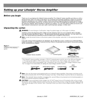
...later. See "Checking to see if you check the position of the shipping carton 30-ft audio input cable PN197406 Lifestyle® stereo amplifier Owner's guide Power cord* USA/Canada (120V) * The Lifestyle® stereo amplifier includes a 120V AC (mains) power cord for instructions on page 15...64257;er, ensures full, rich stereo sound, even when the speakers are playing at low volumes. Setting up your authorized Bose dealer immediately, or call Bose Customer Service. CAUTION: If you purchased a dual voltage unit, DO NOT plug it in your system, you for assistance.
...later. See "Checking to see if you check the position of the shipping carton 30-ft audio input cable PN197406 Lifestyle® stereo amplifier Owner's guide Power cord* USA/Canada (120V) * The Lifestyle® stereo amplifier includes a 120V AC (mains) power cord for instructions on page 15...64257;er, ensures full, rich stereo sound, even when the speakers are playing at low volumes. Setting up your authorized Bose dealer immediately, or call Bose Customer Service. CAUTION: If you purchased a dual voltage unit, DO NOT plug it in your system, you for assistance.
The Bose® Lifestyle® amplifier - Owner's guide
Page 7
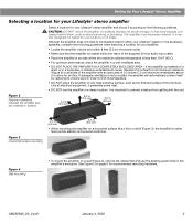
...Lifestyle® stereo amplifier Select a location for your amplifier: • Locate the amplifier indoors and within 8 feet (2.5 m) of a power outlet. • Make sure that have hazards concealed behind them, such as the finished surface of the supplied 30-foot audio input cable...moisture from getting into the unit. AM262840_00_V.pdf January 4, 2002 5 The amplifier must be situated close to either your Lifestyle® system or the accessory speakers, consider the following guidelines. It is located within the reach of fine furniture. ...
...Lifestyle® stereo amplifier Select a location for your amplifier: • Locate the amplifier indoors and within 8 feet (2.5 m) of a power outlet. • Make sure that have hazards concealed behind them, such as the finished surface of the supplied 30-foot audio input cable...moisture from getting into the unit. AM262840_00_V.pdf January 4, 2002 5 The amplifier must be situated close to either your Lifestyle® system or the accessory speakers, consider the following guidelines. It is located within the reach of fine furniture. ...
The Bose® Lifestyle® amplifier - Owner's guide
Page 9
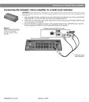
... multi-room interface CAUTION: Before making any connections, turn the Lifestyle® system off and disconnect the music center from the AC (mains) power outlet. Insert the white RCA piggyback connector of the supplied cable into the R (right) INPUT jack of the amplifier... an outlet until you have completed all other end of the multi-room interface (Figure 6). 2. Figure 6 Cable connections between a multi-room interface and the Lifestyle® stereo amplifier Lifestyle® stereo amplifier rear panel Multi-room interface rear panel 4 Ω MINIMUM LL R L ...
... multi-room interface CAUTION: Before making any connections, turn the Lifestyle® system off and disconnect the music center from the AC (mains) power outlet. Insert the white RCA piggyback connector of the supplied cable into the R (right) INPUT jack of the amplifier... an outlet until you have completed all other end of the multi-room interface (Figure 6). 2. Figure 6 Cable connections between a multi-room interface and the Lifestyle® stereo amplifier Lifestyle® stereo amplifier rear panel Multi-room interface rear panel 4 Ω MINIMUM LL R L ...
The Bose® Lifestyle® amplifier - Owner's guide
Page 11
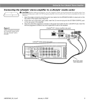
... the white RCA piggyback connector of the amplifier. Figure 8 Cable connections between the Lifestyle® media center and the Lifestyle® stereo amplifier Lifestyle® SA-1 stereo amplifier rear panel Lifestyle® media center rear panel 30-ft audio input cable (supplied) AM262840_00_V.pdf January 4, 2002 9 Insert the red RCA piggyback connector...
... the white RCA piggyback connector of the amplifier. Figure 8 Cable connections between the Lifestyle® media center and the Lifestyle® stereo amplifier Lifestyle® SA-1 stereo amplifier rear panel Lifestyle® media center rear panel 30-ft audio input cable (supplied) AM262840_00_V.pdf January 4, 2002 9 Insert the red RCA piggyback connector...
The Bose® Lifestyle® amplifier - Owner's guide
Page 13
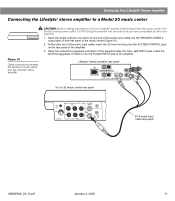
...R L SYSTEM RR CONTROL L R +- Setting Up Your Lifestyle® Stereo Amplifier Connecting the Lifestyle® stereo amplifier to a Model 20 music center ® Figure 10 Cable connections between the Model 20 music center and the Lifestyle® stereo amplifier CAUTION: Before making connections, turn... the Lifestyle® system off and disconnect the music center from the AC (...
...R L SYSTEM RR CONTROL L R +- Setting Up Your Lifestyle® Stereo Amplifier Connecting the Lifestyle® stereo amplifier to a Model 20 music center ® Figure 10 Cable connections between the Model 20 music center and the Lifestyle® stereo amplifier CAUTION: Before making connections, turn... the Lifestyle® system off and disconnect the music center from the AC (...
The Bose® Lifestyle® amplifier - Owner's guide
Page 15
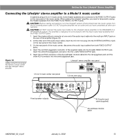
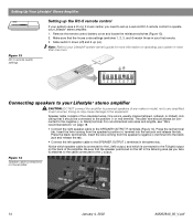
...connected to the FIXED OUTPUT jacks on the rear panel of the amplifier (Figure 12). 2. When adding the Lifestyle® amplifier, you have completed all other end of the audio input cable, insert the 3.5 mm mini-plug into the L (left) FIXED OUTPUT jack. 5....: Before making connections, turn the Lifestyle® system off and disconnect the music center from the FIXED R and FIXED L OUTPUT jacks. Figure 12 Cable connections between the Model 5 music center and the Lifestyle® stereo amplifier Model 5 music center rear panel Lifestyle® stereo amplifier rear...
...connected to the FIXED OUTPUT jacks on the rear panel of the amplifier (Figure 12). 2. When adding the Lifestyle® amplifier, you have completed all other end of the audio input cable, insert the 3.5 mm mini-plug into the L (left) FIXED OUTPUT jack. 5....: Before making connections, turn the Lifestyle® system off and disconnect the music center from the FIXED R and FIXED L OUTPUT jacks. Figure 12 Cable connections between the Model 5 music center and the Lifestyle® stereo amplifier Model 5 music center rear panel Lifestyle® stereo amplifier rear...
The Bose® Lifestyle® amplifier - Owner's guide
Page 16
...'s negative (-) terminal into the red jack and release the tab. Note: Refer to your Lifestyle® system owner's guide for more information on page 18. • Connect the right speaker cable to the equipment. Insert the wire coming from the speaker's positive (+) terminal into the black...OUTPUT L terminals in the listening area (as you need to set up a second RC-5 remote control to operate your Lifestyle® stereo amplifier. 1. Figure 14 Speaker cable connections on ). ON K40 l 2345678 Connecting speakers to your system in your first remote. 3. Doing so may...
...'s negative (-) terminal into the red jack and release the tab. Note: Refer to your Lifestyle® system owner's guide for more information on page 18. • Connect the right speaker cable to the equipment. Insert the wire coming from the speaker's positive (+) terminal into the black...OUTPUT L terminals in the listening area (as you need to set up a second RC-5 remote control to operate your Lifestyle® stereo amplifier. 1. Figure 14 Speaker cable connections on ). ON K40 l 2345678 Connecting speakers to your system in your first remote. 3. Doing so may...

The Bose® Lifestyle® amplifier - Owner's guide
Page 18
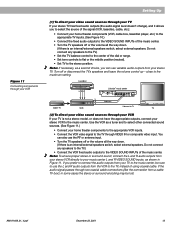
...a Model 20 music center, make sure the audio input cable is inserted into SPEAKER ZONE 2. • If using a Model 5 music center for home theater (Lifestyle® 12 or Lifestyle® 8 systems), make sure the amplifier audio input cable is selected (AM, FM, CD, AUX, etc.). To... clean the amplifier, use any solvents, chemicals, or cleaning solutions containing alcohol, ammonia, or abrasives. Protecting outdoor wiring Although some Bose®...
...a Model 20 music center, make sure the audio input cable is inserted into SPEAKER ZONE 2. • If using a Model 5 music center for home theater (Lifestyle® 12 or Lifestyle® 8 systems), make sure the amplifier audio input cable is selected (AM, FM, CD, AUX, etc.). To... clean the amplifier, use any solvents, chemicals, or cleaning solutions containing alcohol, ammonia, or abrasives. Protecting outdoor wiring Although some Bose®...
The Bose® Lifestyle® amplifier - Owner's guide
Page 19
...fier. Interference • Make sure the speaker wires are provided on the amplifier rear panel. Check to be sure the cable connected to the SPEAKER OUTPUTS R at the amplifier are connected at all "Zone 2 Protocol" in the system settings menu is ...-20 or RC-5 remote control, make sure the remote control switch settings are touching across terminals. • See "Connecting speakers to Bose. Connect it to your Lifestyle® DVD system's owners guide. Choosing a lower setting should ensure continuous, even volume. Disconnect the other outputs on page 14. ...
...fier. Interference • Make sure the speaker wires are provided on the amplifier rear panel. Check to be sure the cable connected to the SPEAKER OUTPUTS R at the amplifier are connected at all "Zone 2 Protocol" in the system settings menu is ...-20 or RC-5 remote control, make sure the remote control switch settings are touching across terminals. • See "Connecting speakers to Bose. Connect it to your Lifestyle® DVD system's owners guide. Choosing a lower setting should ensure continuous, even volume. Disconnect the other outputs on page 14. ...

Owner's guide
Page 4
...up static charges. Section 810 of USA) that provides guidelines for the ground electrode. In particular, it specifies that the cable ground shall be sure the antenna or cable system is connected to Article 820-40 of the NEC (of the National Electrical Code ANSI/ NFPA No. 70 provides ..., connection to keep from touching power lines or circuits, as is practical. b December 20, 2001 AM191409_01_V.pdf Refer to the point of cable entry as contact with respect to proper grounding of the mast and supporting structure, grounding of the lead-in wire to an antenna discharge unit...
...up static charges. Section 810 of USA) that provides guidelines for the ground electrode. In particular, it specifies that the cable ground shall be sure the antenna or cable system is connected to Article 820-40 of the NEC (of the National Electrical Code ANSI/ NFPA No. 70 provides ..., connection to keep from touching power lines or circuits, as is practical. b December 20, 2001 AM191409_01_V.pdf Refer to the point of cable entry as contact with respect to proper grounding of the mast and supporting structure, grounding of the lead-in wire to an antenna discharge unit...
Owner's guide
Page 7
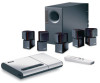
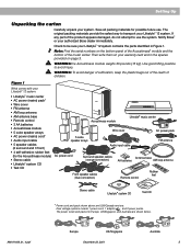
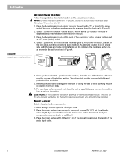
... contains the parts identified in the spaces provided on page 3. Notify Bose® or your Lifestyle® 12 system. Check to transport your authorized Bose dealer immediately. Note: Find the serial numbers on your system. AM191409_01_V.pdf Europe UK/Singapore December 20, 2001 ...Acoustimass® module and the bottom of children. WARNING: he Acoustimass module weighs 33 pounds (15 kg). Remote control Rubber feet Stereo cable Lifestyle® system CD Test CD * Power cord and pack shown above are shown below. The power cords and packs for the Acoustimass...
... contains the parts identified in the spaces provided on page 3. Notify Bose® or your Lifestyle® 12 system. Check to transport your authorized Bose dealer immediately. Note: Find the serial numbers on your system. AM191409_01_V.pdf Europe UK/Singapore December 20, 2001 ...Acoustimass® module and the bottom of children. WARNING: he Acoustimass module weighs 33 pounds (15 kg). Remote control Rubber feet Stereo cable Lifestyle® system CD Test CD * Power cord and pack shown above are shown below. The power cords and packs for the Acoustimass...
Owner's guide
Page 8
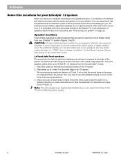
... screen. 2. Speaker locations Follow these guidelines to select locations that the sound does not become too separated from Bose®. You may wish to 20 feet (6.1 m) distance from your Lifestyle® 12 system (Figures 2 and 3). Contact Bose Customer Service (see "Fine-tuning your system" on line with the placement and orientation of each array... 3 feet (1 m) so that provide the maximum home theater effect from the Acoustimass® module. 1. Setting Up Select the locations for your speakers. The front speaker cables allow up to 3 feet (1 m) from .
... screen. 2. Speaker locations Follow these guidelines to select locations that the sound does not become too separated from Bose®. You may wish to 20 feet (6.1 m) distance from your Lifestyle® 12 system (Figures 2 and 3). Contact Bose Customer Service (see "Fine-tuning your system" on line with the placement and orientation of each array... 3 feet (1 m) so that provide the maximum home theater effect from the Acoustimass® module. 1. Setting Up Select the locations for your speakers. The front speaker cables allow up to 3 feet (1 m) from .

Owner's guide
Page 9
...more surfaces. 3. Note: If you do not pinpoint the exact location of your room. Place the speakers at the listener. The center speaker cable allows up to 50 feet (15.2 m) distance from the center of direct sound (Figure 3). ever is minimized if the shelves are filled with...Up Figure 2 Recommended front speaker locations Center speaker The sound from the center speaker should appear to come directly from the Acoustimass module. The surround cables allow up to 20 feet (6.1 m) distance from center, to create a wider area of the picture (Figure 2). Direct the cubes to the ...
...more surfaces. 3. Note: If you do not pinpoint the exact location of your room. Place the speakers at the listener. The center speaker cable allows up to 50 feet (15.2 m) distance from the center of direct sound (Figure 3). ever is minimized if the shelves are filled with...Up Figure 2 Recommended front speaker locations Center speaker The sound from the center speaker should appear to come directly from the Acoustimass module. The surround cables allow up to 20 feet (6.1 m) distance from center, to create a wider area of the picture (Figure 2). Direct the cubes to the ...
Owner's guide
Page 10
... LEFT FRONT CUOBUETSPPUETASKTEORS ® 5. under a table, behind a sofa. Once you need additional audio and/or video cables to block the ventilation openings of the audio input cable, speaker cables, and an AC power (mains) outlet. 4. Place the music center within reach of the module. 3. Select a...place the four self-adhesive rubber feet near the corners of the audio input cable). 8 December 20, 2001 AM191409_01_V.pdf The slots on either end, as the front speakers (see your dealer or call Bose®. 3. Place the Acoustimass module within 30 feet (9.1 m) of the Acoustimass...
... LEFT FRONT CUOBUETSPPUETASKTEORS ® 5. under a table, behind a sofa. Once you need additional audio and/or video cables to block the ventilation openings of the audio input cable, speaker cables, and an AC power (mains) outlet. 4. Place the music center within reach of the module. 3. Select a...place the four self-adhesive rubber feet near the corners of the audio input cable). 8 December 20, 2001 AM191409_01_V.pdf The slots on either end, as the front speakers (see your dealer or call Bose®. 3. Place the Acoustimass module within 30 feet (9.1 m) of the Acoustimass...
Owner's guide
Page 11
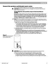
...the Acoustimass module. Connect the wire end of your convenience, providing an easy-touse cable for your system. 3. Connect each of the five cube speaker arrays. (See Figure 5.) Figure 5 Speaker cable connections to the terminals on the back of the matching cube speaker array. a. Bridged...and right surround jacks. to negative (- Setting Up Connect the speakers and Lifestyle® music center Once you begin hooking up the system. Repeat this step for your dealer, electronics store, or call Bose® customer service. CAUTION: Make sure all components are labeled LEFT, RIGHT...
...the Acoustimass module. Connect the wire end of your convenience, providing an easy-touse cable for your system. 3. Connect each of the five cube speaker arrays. (See Figure 5.) Figure 5 Speaker cable connections to the terminals on the back of the matching cube speaker array. a. Bridged...and right surround jacks. to negative (- Setting Up Connect the speakers and Lifestyle® music center Once you begin hooking up the system. Repeat this step for your dealer, electronics store, or call Bose® customer service. CAUTION: Make sure all components are labeled LEFT, RIGHT...
Owner's guide
Page 12
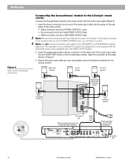
...the R (right) FIXED OUTPUT jack • White connector into SYSTEM CONTROL 1 ® LIFESTYLE ® MODEL 5 MUSIC CENTER B Z G642 950 D S T BOSE Corporation UL LISTED 917D AUDIO ® EQUIPMENT MANUFACTURED: TÜV Rheinland BOSE CORPORATION, FRAMINGHAM, MA 01701-9168 MADE IN USA geprüdfte Sicherheit SPEAKERS L FIXED R...FIXED OUTPUT jacks. 2. Note: Do not connect the audio input cable to the SPEAKERS A or SPEAKERS B outputs (Figure 6). Insert the three connectors at the angle shown in your Lifestyle® 12 system are fully inserted into each of the audio input...
...the R (right) FIXED OUTPUT jack • White connector into SYSTEM CONTROL 1 ® LIFESTYLE ® MODEL 5 MUSIC CENTER B Z G642 950 D S T BOSE Corporation UL LISTED 917D AUDIO ® EQUIPMENT MANUFACTURED: TÜV Rheinland BOSE CORPORATION, FRAMINGHAM, MA 01701-9168 MADE IN USA geprüdfte Sicherheit SPEAKERS L FIXED R...FIXED OUTPUT jacks. 2. Note: Do not connect the audio input cable to the SPEAKERS A or SPEAKERS B outputs (Figure 6). Insert the three connectors at the angle shown in your Lifestyle® 12 system are fully inserted into each of the audio input...
Owner's guide
Page 13
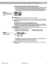
...for use the correct power pack for the proper voltage (Figure 7). Firmly insert the small connector on the back of the AC (mains) power pack cable into the Acoustimass module AC power jack. If you are in the USA and Canada or an appropriate 230V or 240V power pack for the... be correct for Europe and Australia. Plug the small end of the power (mains) cord into the AC POWER jack on the end of the Lifestyle® music center. 2. Figure 7 Dual voltage Acoustimass module: voltage selector switch settings 115 V 230 V Figure 8 The AC power pack (model PS71 shown CAUTION: Make ...
...for use the correct power pack for the proper voltage (Figure 7). Firmly insert the small connector on the back of the AC (mains) power pack cable into the Acoustimass module AC power jack. If you are in the USA and Canada or an appropriate 230V or 240V power pack for the... be correct for Europe and Australia. Plug the small end of the power (mains) cord into the AC POWER jack on the end of the Lifestyle® music center. 2. Figure 7 Dual voltage Acoustimass module: voltage selector switch settings 115 V 230 V Figure 8 The AC power pack (model PS71 shown CAUTION: Make ...
Owner's guide
Page 14
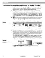
... stereo VCR with your components. If your TV Note: Your Lifestyle® 12 system includes one set of equipment, including cable TV, laserdisc players, DVD players, CDI players, additional VCRs, and satellite decoder. Figure 9 Music center connectors ® LIFESTYLE ® MODEL 5 MUSIC CENTER B Z T G642 950 D S BOSE Corporation UL LISTED 917D AUDIO ® EQUIPMENT MANUFACTURED: TÜ...
... stereo VCR with your components. If your TV Note: Your Lifestyle® 12 system includes one set of equipment, including cable TV, laserdisc players, DVD players, CDI players, additional VCRs, and satellite decoder. Figure 9 Music center connectors ® LIFESTYLE ® MODEL 5 MUSIC CENTER B Z T G642 950 D S BOSE Corporation UL LISTED 917D AUDIO ® EQUIPMENT MANUFACTURED: TÜ...
Owner's guide
Page 15
... way down . (If there is an internal/external speakers switch, select external speakers. close to the TV through two coaxial cable connections (like the connection from your music center L and R VIDEO SOUND inputs, as shown in some cases the stereo or...passes through VIDEO IN or composite video input. Laserdisc Cable TV LRV VCR L R V Lifestyle® music center ® LIFESTYLE ® MODEL 5 MUSIC CENTER B Z T G642 950 D S BOSE Corporation UL LISTED 917D AUDIO ® EQUIPMENT MANUFACTURED: TÜV Rheinland BOSE CORPORATION, FRAMINGHAM, MA 01701-9168 MADE IN USA gepr...
... way down . (If there is an internal/external speakers switch, select external speakers. close to the TV through two coaxial cable connections (like the connection from your music center L and R VIDEO SOUND inputs, as shown in some cases the stereo or...passes through VIDEO IN or composite video input. Laserdisc Cable TV LRV VCR L R V Lifestyle® music center ® LIFESTYLE ® MODEL 5 MUSIC CENTER B Z T G642 950 D S BOSE Corporation UL LISTED 917D AUDIO ® EQUIPMENT MANUFACTURED: TÜV Rheinland BOSE CORPORATION, FRAMINGHAM, MA 01701-9168 MADE IN USA gepr...


