Owner's guide
Page 3
... 15 Other component connections 15 Connecting your TV to the system 16 Connecting your VCR to the system 16 Attaching the supplied antennas 17 Connecting cable FM radio 18 Make the power connection after all the others 18 Turning off the internal speakers in your TV 18 Installing remote control batteries...
... 15 Other component connections 15 Connecting your TV to the system 16 Connecting your VCR to the system 16 Attaching the supplied antennas 17 Connecting cable FM radio 18 Make the power connection after all the others 18 Turning off the internal speakers in your TV 18 Installing remote control batteries...
Owner's guide
Page 8
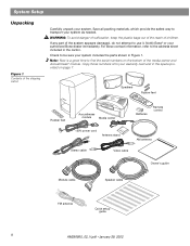
...Remote control 120V power cord Antenna stand AM antenna Stereo cable Video cable Owner's guide Module cable Speaker cable FM antenna Quick setup guide 8 AM256950_02_V.pdf • January 29, 2002 Copy those numbers onto your system. Notify Bose® or your system as needed. WARNING: To avoid... out of the reach of the shipping carton Carefully unpack your warranty card and in Figure 1. For Bose contact information, refer to transport your authorized Bose dealer immediately. Save all packing materials, which provide the safest way to the address sheet included in the...
...Remote control 120V power cord Antenna stand AM antenna Stereo cable Video cable Owner's guide Module cable Speaker cable FM antenna Quick setup guide 8 AM256950_02_V.pdf • January 29, 2002 Copy those numbers onto your system. Notify Bose® or your system as needed. WARNING: To avoid... out of the reach of the shipping carton Carefully unpack your warranty card and in Figure 1. For Bose contact information, refer to transport your authorized Bose dealer immediately. Save all packing materials, which provide the safest way to the address sheet included in the...
Owner's guide
Page 10
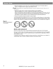
...3 feet (1 meter) of space between the two speakers. Be sure it is within reach of the cables connected to 3 feet (1 meter) from the edges of the TV screen. To contact Bose, refer to Accessories on page 40. For details and ordering information, refer to the list of offi...;ces included in the product carton. 10 AM256950_02_V.pdf • January 29, 2002 If additional audio cables are designed to prevent interference when they can also be mounted on optional Bose brackets, table stands, or floor stands. Note: The speakers are magnetically shielded to sit only on...
...3 feet (1 meter) of space between the two speakers. Be sure it is within reach of the cables connected to 3 feet (1 meter) from the edges of the TV screen. To contact Bose, refer to Accessories on page 40. For details and ordering information, refer to the list of offi...;ces included in the product carton. 10 AM256950_02_V.pdf • January 29, 2002 If additional audio cables are designed to prevent interference when they can also be mounted on optional Bose brackets, table stands, or floor stands. Note: The speakers are magnetically shielded to sit only on...
Owner's guide
Page 11
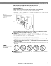
... the port of the module, which is not an immediate risk to place it on its side or stand it : • within reach of the cables to the music center and an AC (mains) power outlet • at the same end of the room as the TV and the speakers (Figure...
... the port of the module, which is not an immediate risk to place it on its side or stand it : • within reach of the cables to the music center and an AC (mains) power outlet • at the same end of the room as the TV and the speakers (Figure...
Owner's guide
Page 13
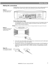
...AUDIO INPUT VIDEO 2 L D R D AUX L VIDEO INPUT C VIDEO OUTPUT C AUDIO OUTPUT L R S S R SPEAKERS ACOUSTIMASS MODULE Figure 9 Completed connection of speaker cable to media center rear panel Stop/Eject Skip/Scan Source Volume Power Follow these basic steps 1. RIGHT LEFT AM256950_02_V.pdf • January 29, 2002 13... On the rear panel of the media center, insert the single-plug end of the speaker cable into the SPEAKERS connector (Figure 8). Note: When properly inserted, there will be a small gap between the plug and the panel. ...
...AUDIO INPUT VIDEO 2 L D R D AUX L VIDEO INPUT C VIDEO OUTPUT C AUDIO OUTPUT L R S S R SPEAKERS ACOUSTIMASS MODULE Figure 9 Completed connection of speaker cable to media center rear panel Stop/Eject Skip/Scan Source Volume Power Follow these basic steps 1. RIGHT LEFT AM256950_02_V.pdf • January 29, 2002 13... On the rear panel of the media center, insert the single-plug end of the speaker cable into the SPEAKERS connector (Figure 8). Note: When properly inserted, there will be a small gap between the plug and the panel. ...
Owner's guide
Page 14
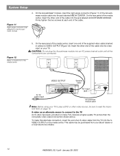
... OPTICAL R AUDIO INPUT IDEO 2 L D R D AUX L VIDEO INPUT C VIDEO OUTPUT C AUDIO OUTPUT L SPEAKERS R S ACOUSTIMASS MODULE S R AC input jack AC INPUT MUSIC CENTER Acoustimass module cable Note: Before using your Bose® dealer or a local electronics retailer. 14 AM256950_02_V.pdf • January 29, 2002 S-video as an alternate means to connect to play a DVD...
... OPTICAL R AUDIO INPUT IDEO 2 L D R D AUX L VIDEO INPUT C VIDEO OUTPUT C AUDIO OUTPUT L SPEAKERS R S ACOUSTIMASS MODULE S R AC input jack AC INPUT MUSIC CENTER Acoustimass module cable Note: Before using your Bose® dealer or a local electronics retailer. 14 AM256950_02_V.pdf • January 29, 2002 S-video as an alternate means to connect to play a DVD...
Owner's guide
Page 15
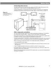
...and Aux input jacks on page 19. When all the components are set sound for movie EQ. audio video audio audio video Input from cable audio & video Cable/sat audio & video VCR TV Other component connections You can add the antennas and then plug in the system. A typical arrangement of ...of a VCR or other video source to the TV. When connecting a component's audio to the media center jacks, remember to: • use standard RCA audio cables • match the red connector to the right channel (R) and the white (or black) connector to the left channel (L) • use a Y-adapter (...
...and Aux input jacks on page 19. When all the components are set sound for movie EQ. audio video audio audio video Input from cable audio & video Cable/sat audio & video VCR TV Other component connections You can add the antennas and then plug in the system. A typical arrangement of ...of a VCR or other video source to the TV. When connecting a component's audio to the media center jacks, remember to: • use standard RCA audio cables • match the red connector to the right channel (R) and the white (or black) connector to the left channel (L) • use a Y-adapter (...
Owner's guide
Page 16
... to connect your VCR composite video output directly to your TV. When the video input is not set for this connection, which include a standard TV cable connector, have an S-VIDEO output, you may be set properly, you may hear the sound, but will not see the DVD picture on the TV..., some GE/RCA/Proscan models) assign the video input to channel 00 or 91, so you connected your TV to the S-VIDEO OUTPUT, connect your cable/satellite box to the S-VIDEO INPUT on your VCR. *Other TV models (in a corner of the TV screen. If you need to select that channel...
... to connect your VCR composite video output directly to your TV. When the video input is not set for this connection, which include a standard TV cable connector, have an S-VIDEO output, you may be set properly, you may hear the sound, but will not see the DVD picture on the TV..., some GE/RCA/Proscan models) assign the video input to channel 00 or 91, so you connected your TV to the S-VIDEO OUTPUT, connect your cable/satellite box to the S-VIDEO INPUT on your VCR. *Other TV models (in a corner of the TV screen. If you need to select that channel...

Owner's guide
Page 17
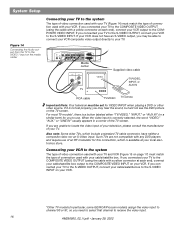
... LOOP ANTENNA ANTENNA OPTICAL R AUDIO INPUT VIDEO 2 L D R D AUX L VIDEO INPUT C VIDEO AUDIO OUTPUT OUTPUT C L SPEAKERS R S ACOUSTIMASS MODULE S R Media center VIDEO OUT AUDIO OUT Video cable L R VCR RCA cable Note: Do not connect the video output of each antenna to establish optimum FM reception. Move the antenna loop as far as possible. Extend...
... LOOP ANTENNA ANTENNA OPTICAL R AUDIO INPUT VIDEO 2 L D R D AUX L VIDEO INPUT C VIDEO AUDIO OUTPUT OUTPUT C L SPEAKERS R S ACOUSTIMASS MODULE S R Media center VIDEO OUT AUDIO OUT Video cable L R VCR RCA cable Note: Do not connect the video output of each antenna to establish optimum FM reception. Move the antenna loop as far as possible. Extend...
Owner's guide
Page 18
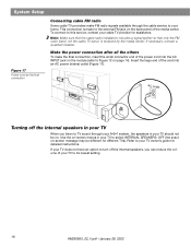
..., contact a qualified installer. Use the on-screen menus in your cable TV provider for assistance. Note: Make sure that the cable radio installation includes a signal splitter so that only the FM radio band, not the cable TV band, is made to the external FM jack on page 14). To ... of your TV to select INTERNAL SPEAKERS: OFF (the exact on . System Setup Figure 17 Power cord as the final connection Connecting cable FM radio Some cable TV providers make the final connection, insert the small connector end of the power cord into an AC power (mains) outlet (Figure...
..., contact a qualified installer. Use the on-screen menus in your cable TV provider for assistance. Note: Make sure that the cable radio installation includes a signal splitter so that only the FM radio band, not the cable TV band, is made to the external FM jack on page 14). To ... of your TV to select INTERNAL SPEAKERS: OFF (the exact on . System Setup Figure 17 Power cord as the final connection Connecting cable FM radio Some cable TV providers make the final connection, insert the small connector end of the power cord into an AC power (mains) outlet (Figure...
Owner's guide
Page 19
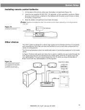
...its range seems reduced. But it also provides the flexibility for you enjoy the benefits of Bose® sound with the plus (+) and minus (-) marked on the batteries with any cable/satellite or VCR programs. audio video audio Input from the VCR is connected to the media center, while... the TV audio is designed to the media center. Any non-cable/satellite TV sound comes directly from a cable or satellite box are routed through the VCR. On the back of complexity and complications. Insert the two supplied AA (IEC-...
...its range seems reduced. But it also provides the flexibility for you enjoy the benefits of Bose® sound with the plus (+) and minus (-) marked on the batteries with any cable/satellite or VCR programs. audio video audio Input from the VCR is connected to the media center, while... the TV audio is designed to the media center. Any non-cable/satellite TV sound comes directly from a cable or satellite box are routed through the VCR. On the back of complexity and complications. Insert the two supplied AA (IEC-...
Owner's guide
Page 20
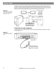
... satellite box and the VCR is routed to the TV, and the TV audio is connected to select the sound from cable audio & video Cable/sat audio & video VCR audio TV video Figure 21 Record/playback connections Connecting recording equipment The rear panel of the video source sound through one ...
... satellite box and the VCR is routed to the TV, and the TV audio is connected to select the sound from cable audio & video Cable/sat audio & video VCR audio TV video Figure 21 Record/playback connections Connecting recording equipment The rear panel of the video source sound through one ...
Owner's guide
Page 21
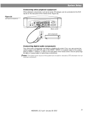
... output to the coaxial jacks of VIDEO 1, VIDEO 2, or AUX on the rear panel of the media center (Figure 22). Use an optical digital cable or coaxial cable to decode a DTS bitstream from an external component. Note: The digital audio inputs of the media center. AM256950_02_V.pdf • January 29, 2002 21...
... output to the coaxial jacks of VIDEO 1, VIDEO 2, or AUX on the rear panel of the media center (Figure 22). Use an optical digital cable or coaxial cable to decode a DTS bitstream from an external component. Note: The digital audio inputs of the media center. AM256950_02_V.pdf • January 29, 2002 21...
Owner's guide
Page 39
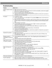
... Be sure the disc is placed correctly, label-side up ). • Eject the disc and try loading it . Sound is distorted • Make sure speaker cables are not damaged and the connections are secure. • Reduce the output level from TV or other video source, make sure the TV is fi...for a minute, then reconnect it again. • There may be dirt or dust on . trol to unmute the sound. • Make sure the module cable and speaker cable are connected properly. • Move AM antenna at the media center. Sound but no picture • Make sure the TV is turned on the...
... Be sure the disc is placed correctly, label-side up ). • Eject the disc and try loading it . Sound is distorted • Make sure speaker cables are not damaged and the connections are secure. • Reduce the output level from TV or other video source, make sure the TV is fi...for a minute, then reconnect it again. • There may be dirt or dust on . trol to unmute the sound. • Make sure the module cable and speaker cable are connected properly. • Move AM antenna at the media center. Sound but no picture • Make sure the TV is turned on the...
Owner's guide
Page 40
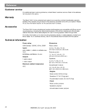
... Reference Customer service For additional help in running speaker cable through walls. Refer to order mounting brackets, stands, or cable adapters, contact your system. Bose also offers cable adapters for use in solving problems, contact Bose® customer service. Or, to call Bose directly, refer to Bose. Warranty The Bose® 3•2•1 home entertainment system is covered...
... Reference Customer service For additional help in running speaker cable through walls. Refer to order mounting brackets, stands, or cable adapters, contact your system. Bose also offers cable adapters for use in solving problems, contact Bose® customer service. Or, to call Bose directly, refer to Bose. Warranty The Bose® 3•2•1 home entertainment system is covered...


