Owner's guide
Page 3
... 15 Other component connections 15 Connecting your TV to the system 16 Connecting your VCR to the system 16 Attaching the supplied antennas 17 Connecting cable FM radio 18 Make the power connection after all the others 18 Turning off the internal speakers in your TV 18 Installing remote control batteries...
... 15 Other component connections 15 Connecting your TV to the system 16 Connecting your VCR to the system 16 Attaching the supplied antennas 17 Connecting cable FM radio 18 Make the power connection after all the others 18 Turning off the internal speakers in your TV 18 Installing remote control batteries...
Owner's guide
Page 8
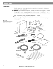
...avoid danger of suffocation, keep the plastic bags out of the reach of the media center and Acoustimass® module. For Bose contact information, refer to the address sheet included in the space provided on the bottom of children. Speakers Rubber feet Rubber ...module Media center Batteries Remote control 120V power cord Antenna stand AM antenna Stereo cable Video cable Owner's guide Module cable Speaker cable FM antenna Quick setup guide 8 AM256950_02_V.pdf • January 29, 2002 Notify Bose® or your system includes the parts shown in Figure 1. Copy those numbers...
...avoid danger of suffocation, keep the plastic bags out of the reach of the media center and Acoustimass® module. For Bose contact information, refer to the address sheet included in the space provided on the bottom of children. Speakers Rubber feet Rubber ...module Media center Batteries Remote control 120V power cord Antenna stand AM antenna Stereo cable Video cable Owner's guide Module cable Speaker cable FM antenna Quick setup guide 8 AM256950_02_V.pdf • January 29, 2002 Notify Bose® or your system includes the parts shown in Figure 1. Copy those numbers...
Owner's guide
Page 10
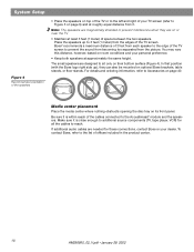
...it is within reach of space between the two speakers. The small speakers are needed for all the cables to the Acoustimass® module and the speakers. In that position (with the Bose logo right side up to sit only on page 40. For details and ordering information, refer to prevent... interference when they can also be mounted on or near the TV. • Maintain at least 3 feet (1 meter) of the cables connected to reach. Media center ...
...it is within reach of space between the two speakers. The small speakers are needed for all the cables to the Acoustimass® module and the speakers. In that position (with the Bose logo right side up to sit only on page 40. For details and ordering information, refer to prevent... interference when they can also be mounted on or near the TV. • Maintain at least 3 feet (1 meter) of the cables connected to reach. Media center ...
Owner's guide
Page 11
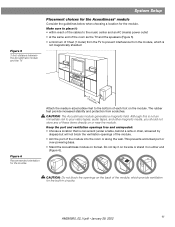
... guidelines below when choosing a location for the built-in circuitry. Do not lay it on its side or stand it : • within reach of the cables to place it on the module.
... guidelines below when choosing a location for the built-in circuitry. Do not lay it on its side or stand it : • within reach of the cables to place it on the module.
Owner's guide
Page 13
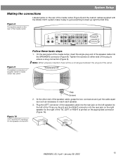
...R AUDIO INPUT VIDEO 2 L D R D AUX L VIDEO INPUT C VIDEO OUTPUT C AUDIO OUTPUT L R S S R SPEAKERS ACOUSTIMASS MODULE Figure 9 Completed connection of speaker cable to media center rear panel Stop/Eject Skip/Scan Source Volume Power Follow these basic steps 1. System Setup Making the connections Labeled jacks on the... rear of the media center (Figure 8) and the custom cables supplied with the Model 3•2•1 system make it ) and the RIGHT connector into the rear jack on the right speaker ...
...R AUDIO INPUT VIDEO 2 L D R D AUX L VIDEO INPUT C VIDEO OUTPUT C AUDIO OUTPUT L R S S R SPEAKERS ACOUSTIMASS MODULE Figure 9 Completed connection of speaker cable to media center rear panel Stop/Eject Skip/Scan Source Volume Power Follow these basic steps 1. System Setup Making the connections Labeled jacks on the... rear of the media center (Figure 8) and the custom cables supplied with the Model 3•2•1 system make it ) and the RIGHT connector into the rear jack on the right speaker ...
Owner's guide
Page 14
... the video input on your TV to read the Important Note on page 16. This cable may be sure to play a DVD or other end of an S-video cable from your Bose® dealer or a local electronics retailer. 14 AM256950_02_V.pdf • January 29, 2002 To make this alternate ...connection, insert the end of the cable into the SVIDEO OUTPUT on the media center. System Setup Figure...
... the video input on your TV to read the Important Note on page 16. This cable may be sure to play a DVD or other end of an S-video cable from your Bose® dealer or a local electronics retailer. 14 AM256950_02_V.pdf • January 29, 2002 To make this alternate ...connection, insert the end of the cable into the SVIDEO OUTPUT on the media center. System Setup Figure...
Owner's guide
Page 15
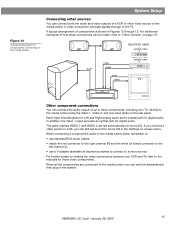
When connecting a component's audio to the media center jacks, remember to: • use standard RCA audio cables • match the red connector to the right channel (R) and the white (or black) connector to the left channel (L) • use a Y-adapter (available ...to three components, including your VCR and TV, refer to "Other choices" on the rear panel. audio video audio audio video Input from cable audio & video Cable/sat audio & video VCR TV Other component connections You can still set automatically for digital audio. When all the components are set sound for...
When connecting a component's audio to the media center jacks, remember to: • use standard RCA audio cables • match the red connector to the right channel (R) and the white (or black) connector to the left channel (L) • use a Y-adapter (available ...to three components, including your VCR and TV, refer to "Other choices" on the rear panel. audio video audio audio video Input from cable audio & video Cable/sat audio & video VCR TV Other component connections You can still set automatically for digital audio. When all the components are set sound for...
Owner's guide
Page 16
...L SPEAKERS R S ACOUSTIMASS MODULE S R Media center VIDEO IN AUDIO OUT L R TV Supplied video cable TV/VIDEO, INPUT, or AUX IN RCA cable TV/VIDEO TV remote Important Note: Your television must match the type of video connection used with your VCR...channel 00 or 91, so you connected your TV to the COMPOSITE VIDEO OUTPUT (using the cable with any DVD players and require use . If you to use of the TV screen.... input is not set for you connected your TV to the S-VIDEO OUTPUT, connect your cable/satellite box to the S-VIDEO INPUT on page 17) must be able to connect your VCR...
...L SPEAKERS R S ACOUSTIMASS MODULE S R Media center VIDEO IN AUDIO OUT L R TV Supplied video cable TV/VIDEO, INPUT, or AUX IN RCA cable TV/VIDEO TV remote Important Note: Your television must match the type of video connection used with your VCR...channel 00 or 91, so you connected your TV to the COMPOSITE VIDEO OUTPUT (using the cable with any DVD players and require use . If you to use of the TV screen.... input is not set for you connected your TV to the S-VIDEO OUTPUT, connect your cable/satellite box to the S-VIDEO INPUT on page 17) must be able to connect your VCR...

Owner's guide
Page 17
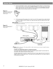
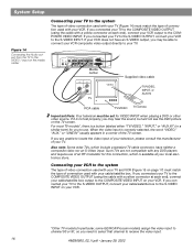
... LOOP ANTENNA ANTENNA OPTICAL R AUDIO INPUT VIDEO 2 L D R D AUX L VIDEO INPUT C VIDEO AUDIO OUTPUT OUTPUT C L SPEAKERS R S ACOUSTIMASS MODULE S R Media center VIDEO OUT AUDIO OUT Video cable L R VCR RCA cable Note: Do not connect the video output of the media center provides jacks for optimum AM reception. 3. Attaching the supplied antennas The rear panel...
... LOOP ANTENNA ANTENNA OPTICAL R AUDIO INPUT VIDEO 2 L D R D AUX L VIDEO INPUT C VIDEO AUDIO OUTPUT OUTPUT C L SPEAKERS R S ACOUSTIMASS MODULE S R Media center VIDEO OUT AUDIO OUT Video cable L R VCR RCA cable Note: Do not connect the video output of the media center provides jacks for optimum AM reception. 3. Attaching the supplied antennas The rear panel...
Owner's guide
Page 18
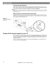
...made to the external FM jack on the back panel of your TV to your cable TV provider for different TVs). Insert the large end of the power cord into ... off the internal speakers in your TV When you listen to TV sound through the cable service to your TV should not be different for assistance. System Setup Figure 17 Power cord as the... final connection Connecting cable FM radio Some cable TV providers make the final connection, insert the small connector end of the cord into...
...made to the external FM jack on the back panel of your TV to your cable TV provider for different TVs). Insert the large end of the power cord into ... off the internal speakers in your TV When you listen to TV sound through the cable service to your TV should not be different for assistance. System Setup Figure 17 Power cord as the... final connection Connecting cable FM radio Some cable TV providers make the final connection, insert the small connector end of the cord into...
Owner's guide
Page 19
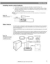
... or VCR programs. audio video audio Input from cable audio & video Cable/sat audio & video VCR video TV AM256950_02_V.pdf • January 29, 2002 19 But it also provides the flexibility for you enjoy the benefits of Bose® sound with the plus (+) and minus (-) inside the ...battery compartment. 3. Any non-cable/satellite TV sound comes directly from the TV The 3•2•1 system is not. Figure 18 Installing...
... or VCR programs. audio video audio Input from cable audio & video Cable/sat audio & video VCR video TV AM256950_02_V.pdf • January 29, 2002 19 But it also provides the flexibility for you enjoy the benefits of Bose® sound with the plus (+) and minus (-) inside the ...battery compartment. 3. Any non-cable/satellite TV sound comes directly from the TV The 3•2•1 system is not. Figure 18 Installing...
Owner's guide
Page 20
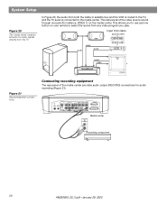
... AM256950_02_V.pdf • January 29, 2002 This delivers all audio-for-video signals directly from the TV In Figure 20, the audio from both the cable or satellite box and the VCR is routed to the TV, and the TV audio is connected to the media center. This allows you to... use just one jack (for instance, VIDEO 1) on your remote to select the sound from cable audio & video Cable/sat audio & video VCR audio TV video Figure 21 Record/playback connections Connecting recording equipment The rear panel of the video source sound through...
... AM256950_02_V.pdf • January 29, 2002 This delivers all audio-for-video signals directly from the TV In Figure 20, the audio from both the cable or satellite box and the VCR is routed to the TV, and the TV audio is connected to the media center. This allows you to... use just one jack (for instance, VIDEO 1) on your remote to select the sound from cable audio & video Cable/sat audio & video VCR audio TV video Figure 21 Record/playback connections Connecting recording equipment The rear panel of the video source sound through...
Owner's guide
Page 21
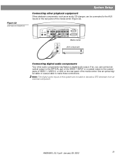
Use an optical digital cable or coaxial cable to decode a DTS bitstream from an external component. VIDEO I D L 75 Ω AM FM LOOP ANTENNA ANTENNA OPTICAL R AUDIO INPUT VIDEO 2 L D R D AUX L VIDEO INPUT C VIDEO AUDIO ...
Use an optical digital cable or coaxial cable to decode a DTS bitstream from an external component. VIDEO I D L 75 Ω AM FM LOOP ANTENNA ANTENNA OPTICAL R AUDIO INPUT VIDEO 2 L D R D AUX L VIDEO INPUT C VIDEO AUDIO ...
Owner's guide
Page 39
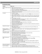
... Unplug the Acoustimass module power cord from any external components connected to the music center. Sound is distorted • Make sure speaker cables are not damaged and the connections are firmly seated in the media center jacks and the multi-pin connector on the other electronic... See Important Note on the display. See "Check for any external components. trol to unmute the sound. • Make sure the module cable and speaker cable are secure. • Reduce the output level from the outlet for 10 seconds, then on the disc. work or has poor reception ...
... Unplug the Acoustimass module power cord from any external components connected to the music center. Sound is distorted • Make sure speaker cables are not damaged and the connections are firmly seated in the media center jacks and the multi-pin connector on the other electronic... See Important Note on the display. See "Check for any external components. trol to unmute the sound. • Make sure the module cable and speaker cable are secure. • Reduce the output level from the outlet for 10 seconds, then on the disc. work or has poor reception ...
Owner's guide
Page 40
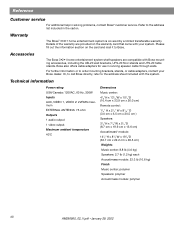
...the warranty card that came with the system. Accessories The Bose 3•2•1 home entertainment system shelf speakers are provided on the card and mail it to order mounting brackets, stands, or cable adapters, contact your system. Technical information Power rating USA/Canada...information or to Bose. Or, to call Bose directly, refer to the address list included in the carton. Refer to the address sheet included with your Bose dealer. Bose also offers cable adapters for use in solving problems, contact Bose® customer service. Warranty The Bose® 3&#...
...the warranty card that came with the system. Accessories The Bose 3•2•1 home entertainment system shelf speakers are provided on the card and mail it to order mounting brackets, stands, or cable adapters, contact your system. Technical information Power rating USA/Canada...information or to Bose. Or, to call Bose directly, refer to the address list included in the carton. Refer to the address sheet included with your Bose dealer. Bose also offers cable adapters for use in solving problems, contact Bose® customer service. Warranty The Bose® 3&#...


