Owner's guide
Page 2
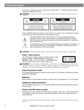
... This Class B digital apparatus meets all of electric shock. It will help you set up and operate your owner's guide for future reference. ©2002 Bose Corporation. AVIS RISQUE DE CHOC ÉLECTRIQUE NE PAS OUVRIR ATTENTION : POUR RÉDUIRE LE RISQUE DE DÉCHARGE ÉLECTRIQUE, NE RETIREZ PAS LE...
... This Class B digital apparatus meets all of electric shock. It will help you set up and operate your owner's guide for future reference. ©2002 Bose Corporation. AVIS RISQUE DE CHOC ÉLECTRIQUE NE PAS OUVRIR ATTENTION : POUR RÉDUIRE LE RISQUE DE DÉCHARGE ÉLECTRIQUE, NE RETIREZ PAS LE...
Owner's guide
Page 3
Contents Where to restrict future play 28 DVD-specific behavior 28 DVD play options 28 Loading and playing a CD 29 Basic CD operations 29 Changing CD settings 30 Using the sleep timer 30 ...continues AM256950_02_V.pdf • January 29, 2002 3 Safety Information 2 Introduction 5 Before you begin 5 Selecting compatible discs 5 How text is used in this owner's guide 5 Glossary of terms 5 For your records 7 System Setup 8 Unpacking 8 Selecting locations for your Model 3•2•1 speakers and media center 9 Placing the small speakers 9 Media center placement 10 ...
Contents Where to restrict future play 28 DVD-specific behavior 28 DVD play options 28 Loading and playing a CD 29 Basic CD operations 29 Changing CD settings 30 Using the sleep timer 30 ...continues AM256950_02_V.pdf • January 29, 2002 3 Safety Information 2 Introduction 5 Before you begin 5 Selecting compatible discs 5 How text is used in this owner's guide 5 Glossary of terms 5 For your records 7 System Setup 8 Unpacking 8 Selecting locations for your Model 3•2•1 speakers and media center 9 Placing the small speakers 9 Media center placement 10 ...
Owner's guide
Page 4
Contents Using the radio 30 Tuning 30 Storing preferred stations as preset selections 31 Selecting a preset station 31 Changing FM settings 31 Changing AM settings 32 Playing other sources 32 Changing settings for the other sources 32 System settings 32 Sound Adjustments 33 Locating Audio Setup 33 Audio Setup menu 33 System Adjustments 35 Locating system settings 35 System Setup menu 36 DVD Setup submenu 36 Parental Control submenu 37 Reference 38 Taking care of your 3•2•1 home entertainment system 38 Cleaning the media center 38 Cleaning the speakers 38 ...
Contents Using the radio 30 Tuning 30 Storing preferred stations as preset selections 31 Selecting a preset station 31 Changing FM settings 31 Changing AM settings 32 Playing other sources 32 Changing settings for the other sources 32 System settings 32 Sound Adjustments 33 Locating Audio Setup 33 Audio Setup menu 33 System Adjustments 35 Locating system settings 35 System Setup menu 36 DVD Setup submenu 36 Parental Control submenu 37 Reference 38 Taking care of your 3•2•1 home entertainment system 38 Cleaning the media center 38 Cleaning the speakers 38 ...
Owner's guide
Page 5
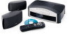
Using Bose proprietary signal processing technology, the 3•2•1 system provides improved spaciousness from stereo recordings, and bold movie effects from surround-encoded materials. On-Screen Display ... connecting other source components (such as 4 by their region code numbers must match. The trademarked logo for Dolby Digital, a perceptual coding system for purchasing the Bose® 3•2•1 home entertainment system, which offers superb sound, elegance, and simplicity in an advanced home audio setup. Introduction Before you begin Thank you...
Using Bose proprietary signal processing technology, the 3•2•1 system provides improved spaciousness from stereo recordings, and bold movie effects from surround-encoded materials. On-Screen Display ... connecting other source components (such as 4 by their region code numbers must match. The trademarked logo for Dolby Digital, a perceptual coding system for purchasing the Bose® 3•2•1 home entertainment system, which offers superb sound, elegance, and simplicity in an advanced home audio setup. Introduction Before you begin Thank you...
Owner's guide
Page 6
NTSC and PAL are examples of feature films is often wider than 525 or 625 line video formats. DTS - DVD - DVD Video - Letterbox - The projected aspect ratio of composite video systems. Dolby* - It is a serial data stream that contains luminance, color, and synchronization information. MPEG-1 Layer III audio. It is becoming common practice to transfer films to the type of music on an infrared light beam. All rights reserved. Reverse engineering or disassembly is prohibited. 6 AM256950_02_V.pdf • January 29, 2002 MPEG Layer-3 audio compression ...
NTSC and PAL are examples of feature films is often wider than 525 or 625 line video formats. DTS - DVD - DVD Video - Letterbox - The projected aspect ratio of composite video systems. Dolby* - It is a serial data stream that contains luminance, color, and synchronization information. MPEG-1 Layer III audio. It is becoming common practice to transfer films to the type of music on an infrared light beam. All rights reserved. Reverse engineering or disassembly is prohibited. 6 AM256950_02_V.pdf • January 29, 2002 MPEG Layer-3 audio compression ...
Owner's guide
Page 7
Introduction S-video - Most high-end televisions have S-video inputs. Individual selections recorded on a four-pin mini-DIN connector. Media center serial number Acoustimass module serial number Dealer name Dealer phone Purchase date We suggest you keep your records Serial numbers are located on the bottom of the media center and the rear of S-video is significantly better than the movie alone. Track - For your sales receipt and warranty card together with this owner's guide. AM256950_02_V.pdf • January 29, 2002 7 The quality of the Acoustimass® module. A...
Introduction S-video - Most high-end televisions have S-video inputs. Individual selections recorded on a four-pin mini-DIN connector. Media center serial number Acoustimass module serial number Dealer name Dealer phone Purchase date We suggest you keep your records Serial numbers are located on the bottom of the media center and the rear of S-video is significantly better than the movie alone. Track - For your sales receipt and warranty card together with this owner's guide. AM256950_02_V.pdf • January 29, 2002 7 The quality of the Acoustimass® module. A...
Owner's guide
Page 8
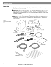
...system. Note: Now is a good time to use it. System Setup Unpacking Figure 1 Contents of the shipping carton Carefully unpack your authorized Bose dealer immediately. WARNING: To avoid danger of suffocation, keep the plastic bags out of the reach of the media center and Acoustimass® ...antenna Quick setup guide 8 AM256950_02_V.pdf • January 29, 2002 Check to be sure your warranty card and in the carton. For Bose contact information, refer to transport your system as needed. Save all packing materials, which provide the safest way to the address sheet included ...
...system. Note: Now is a good time to use it. System Setup Unpacking Figure 1 Contents of the shipping carton Carefully unpack your authorized Bose dealer immediately. WARNING: To avoid danger of suffocation, keep the plastic bags out of the reach of the media center and Acoustimass® ...antenna Quick setup guide 8 AM256950_02_V.pdf • January 29, 2002 Check to be sure your warranty card and in the carton. For Bose contact information, refer to transport your system as needed. Save all packing materials, which provide the safest way to the address sheet included ...
Owner's guide
Page 9
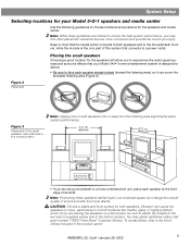
...the broadest listening area (Figure 2). If you enjoy. Keep in a corner position Note: Angling one or both speakers into or away from Bose® Customer Service. You may find other placement variations that are offered to ensure the best system performance, you may obtain additional rubber... only part of this system that connects to a power outlet. Note: While these speakers farther back in the product carton. To contact Bose, refer to the bottom surface. Placing the small speakers Choosing a good location for the speakers will allow you are placing the speakers on...
...the broadest listening area (Figure 2). If you enjoy. Keep in a corner position Note: Angling one or both speakers into or away from Bose® Customer Service. You may find other placement variations that are offered to ensure the best system performance, you may obtain additional rubber... only part of this system that connects to a power outlet. Note: While these speakers farther back in the product carton. To contact Bose, refer to the bottom surface. Placing the small speakers Choosing a good location for the speakers will allow you are placing the speakers on...
Owner's guide
Page 10
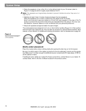
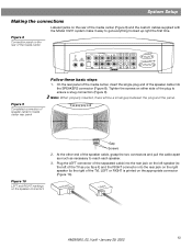
...roughly equal distance from it. Make sure it is close enough to additional source components (TV, tape player, VCR) for these connections, contact Bose or your dealer. Bose® recommends a maximum distance of 3 feet from each speaker to the edge of the TV screen to prevent the sound from becoming too separated...speakers on top of the TV or to the left and right of your TV screen (refer to Figure 3 on optional Bose brackets, table stands, or floor stands. To contact Bose, refer to the list of offices included in the product carton. 10 AM256950_02_V.pdf • January 29, ...
...roughly equal distance from it. Make sure it is close enough to additional source components (TV, tape player, VCR) for these connections, contact Bose or your dealer. Bose® recommends a maximum distance of 3 feet from each speaker to the edge of the TV screen to prevent the sound from becoming too separated...speakers on top of the TV or to the left and right of your TV screen (refer to Figure 3 on optional Bose brackets, table stands, or floor stands. To contact Bose, refer to the list of offices included in the product carton. 10 AM256950_02_V.pdf • January 29, ...
Owner's guide
Page 11
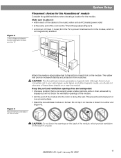
Keep the port and ventilation openings free and unimpeded: • Choose a location that is not an immediate risk to your video tapes, audio tapes, and other magnetic media, you should not store any of the module into the room or along the wall. Although this is convenient (under a table, behind a sofa or chair, screened by drapes) but will not block the ventilation openings of the module. • Aim the port of these items directly on or near the module. CAUTION: The Acoustimass module generates a magnetic field. This prevents a blocked port or over-powering bass. &#...
Keep the port and ventilation openings free and unimpeded: • Choose a location that is not an immediate risk to your video tapes, audio tapes, and other magnetic media, you should not store any of the module into the room or along the wall. Although this is convenient (under a table, behind a sofa or chair, screened by drapes) but will not block the ventilation openings of the module. • Aim the port of these items directly on or near the module. CAUTION: The Acoustimass module generates a magnetic field. This prevents a blocked port or over-powering bass. &#...
Owner's guide
Page 12
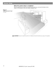
System Setup Figure 7 System placement for ideal coverage When the system setup is completed With the speakers and media center placed as directed, you plug in the room without missing a note. CAUTION: Be sure to read the section on making connections before you can enjoy the freedom to sit, recline, or move about in the system. 12 AM256950_02_V.pdf • January 29, 2002
System Setup Figure 7 System placement for ideal coverage When the system setup is completed With the speakers and media center placed as directed, you plug in the room without missing a note. CAUTION: Be sure to read the section on making connections before you can enjoy the freedom to sit, recline, or move about in the system. 12 AM256950_02_V.pdf • January 29, 2002
Owner's guide
Page 13
Figure 8 Connection panel on the rear of the media center VIDEO 1 D L 75 Ω FM AM LOOP ANTENNA ANTENNA OPTICAL R AUDIO INPUT VIDEO 2 L D R D AUX L VIDEO INPUT C VIDEO OUTPUT C AUDIO OUTPUT L R S S R SPEAKERS ACOUSTIMASS MODULE Figure 9 Completed connection of the media center (Figure 8) and the custom cables supplied with the Model 3•2•1 system make it ) and the RIGHT connector into the SPEAKERS connector (Figure 8). LEFT or RIGHT is printed on the speaker connectors Gap Screws 2. System Setup Making the connections Labeled jacks on the rear of...
Figure 8 Connection panel on the rear of the media center VIDEO 1 D L 75 Ω FM AM LOOP ANTENNA ANTENNA OPTICAL R AUDIO INPUT VIDEO 2 L D R D AUX L VIDEO INPUT C VIDEO OUTPUT C AUDIO OUTPUT L R S S R SPEAKERS ACOUSTIMASS MODULE Figure 9 Completed connection of the media center (Figure 8) and the custom cables supplied with the Model 3•2•1 system make it ) and the RIGHT connector into the SPEAKERS connector (Figure 8). LEFT or RIGHT is printed on the speaker connectors Gap Screws 2. System Setup Making the connections Labeled jacks on the rear of...
Owner's guide
Page 14
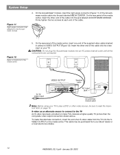
... IDEO 2 L D R D AUX L VIDEO INPUT C VIDEO OUTPUT C AUDIO OUTPUT L SPEAKERS R S ACOUSTIMASS MODULE S R AC input jack AC INPUT MUSIC CENTER Acoustimass module cable Note: Before using your Bose® dealer or a local electronics retailer. 14 AM256950_02_V.pdf • January 29, 2002 System Setup Figure 11 Right-angle connector that attaches to VIDEO OUTPUT...
... IDEO 2 L D R D AUX L VIDEO INPUT C VIDEO OUTPUT C AUDIO OUTPUT L SPEAKERS R S ACOUSTIMASS MODULE S R AC input jack AC INPUT MUSIC CENTER Acoustimass module cable Note: Before using your Bose® dealer or a local electronics retailer. 14 AM256950_02_V.pdf • January 29, 2002 System Setup Figure 11 Right-angle connector that attaches to VIDEO OUTPUT...
Owner's guide
Page 15
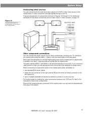
audio video audio audio video Input from cable audio & video Cable/sat audio & video VCR TV Other component connections You can connect the audio output of up to three components, including your VCR and TV, refer to the manuals for digital audio. For additional examples of how these connections can still set automatically for movie EQ. If you connect a video source to AUX, you can connect both the audio and video outputs of components is shown in Figures 13 through to a mono source For further details on -screen menu. System Setup Figure 13 Typical arrangement of ...
audio video audio audio video Input from cable audio & video Cable/sat audio & video VCR TV Other component connections You can connect the audio output of up to three components, including your VCR and TV, refer to the manuals for digital audio. For additional examples of how these connections can still set automatically for movie EQ. If you connect a video source to AUX, you can connect both the audio and video outputs of components is shown in Figures 13 through to a mono source For further details on -screen menu. System Setup Figure 13 Typical arrangement of ...
Owner's guide
Page 16
If you connected your TV to the S-VIDEO OUTPUT, connect your VCR to use of an RF modulator for this connection, which include a standard TV cable connector, have an S-VIDEO output, you may be set properly, you to the S-VIDEO INPUT. For most TV models*, there is not set for you may hear the sound, but will not see the DVD picture on the TV screen. When the video input is available at each end), connect your cable/satellite box output to locate the video input of your television, please consult the manufacturer of connection used with a yellow connector at your VCR output ...
If you connected your TV to the S-VIDEO OUTPUT, connect your VCR to use of an RF modulator for this connection, which include a standard TV cable connector, have an S-VIDEO output, you may be set properly, you to the S-VIDEO INPUT. For most TV models*, there is not set for you may hear the sound, but will not see the DVD picture on the TV screen. When the video input is available at each end), connect your cable/satellite box output to locate the video input of your television, please consult the manufacturer of connection used with a yellow connector at your VCR output ...

Owner's guide
Page 17
To add an outdoor antenna, consult a qualified installer. Extend the antenna as far from the media center and other end and move them around to establish optimum FM reception. AM antenna 1. Follow the instructions enclosed with positioning the loop for AM and FM antennas (Figure 16). Attaching the supplied antennas The rear panel of your 3•2•1 system media center to a VCR; Unwind the wires of the two that are supplied. Experiment with the AM loop antenna to stand it on the supplied base, or mount it to a wall. Spread out the antenna arms at the other ...
To add an outdoor antenna, consult a qualified installer. Extend the antenna as far from the media center and other end and move them around to establish optimum FM reception. AM antenna 1. Follow the instructions enclosed with positioning the loop for AM and FM antennas (Figure 16). Attaching the supplied antennas The rear panel of your 3•2•1 system media center to a VCR; Unwind the wires of the two that are supplied. Experiment with the AM loop antenna to stand it on the supplied base, or mount it to a wall. Spread out the antenna arms at the other ...
Owner's guide
Page 18
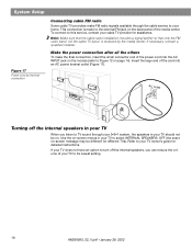
System Setup Figure 17 Power cord as the final connection Connecting cable FM radio Some cable TV providers make the final connection, insert the small connector end of the media center. If your TV does not have an option to turn off the internal speakers in your TV to your cable TV provider for assistance. Insert the large end of your TV should not be different for detailed instructions. Use the on page 14). Refer to its lowest setting. 18 AM256950_02_V.pdf • January 29, 2002 Note: Make sure that the cable radio installation includes a signal splitter ...
System Setup Figure 17 Power cord as the final connection Connecting cable FM radio Some cable TV providers make the final connection, insert the small connector end of the media center. If your TV does not have an option to turn off the internal speakers in your TV to your cable TV provider for assistance. Insert the large end of your TV should not be different for detailed instructions. Use the on page 14). Refer to its lowest setting. 18 AM256950_02_V.pdf • January 29, 2002 Note: Make sure that the cable radio installation includes a signal splitter ...
Owner's guide
Page 19
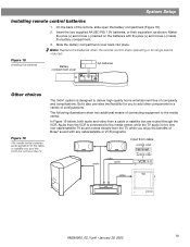
Match the plus (+) and minus (-) inside the battery compartment. 3. But it also provides the flexibility for you enjoy the benefits of Bose® sound with the plus (+) and minus (-) marked on the batteries with any cable/satellite or VCR programs. audio video audio Input from cable audio & ...
Match the plus (+) and minus (-) inside the battery compartment. 3. But it also provides the flexibility for you enjoy the benefits of Bose® sound with the plus (+) and minus (-) marked on the batteries with any cable/satellite or VCR programs. audio video audio Input from cable audio & ...
Owner's guide
Page 20
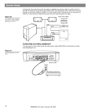
System Setup Figure 20 The media center receives all of the media center provides audio output (RECORD) connections for -video signals directly from the TV In Figure 20, the audio from any video program you to the media center. audio video audio Input from cable audio & video Cable/sat audio & video VCR audio TV video Figure 21 Record/playback connections Connecting recording equipment The rear panel of the video source sound through one button on your remote to select the sound from both the cable or satellite box and the VCR is routed to the TV, and the TV audio is ...
System Setup Figure 20 The media center receives all of the media center provides audio output (RECORD) connections for -video signals directly from the TV In Figure 20, the audio from any video program you to the media center. audio video audio Input from cable audio & video Cable/sat audio & video VCR audio TV video Figure 21 Record/playback connections Connecting recording equipment The rear panel of the video source sound through one button on your remote to select the sound from both the cable or satellite box and the VCR is routed to the TV, and the TV audio is ...
Owner's guide
Page 21
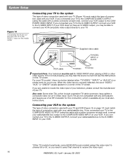
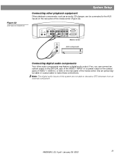
Use an optical digital cable or coaxial cable to decode a DTS bitstream from an external component. VIDEO I D L 75 Ω AM FM LOOP ANTENNA ANTENNA OPTICAL R AUDIO INPUT VIDEO 2 L D R D AUX L VIDEO INPUT C VIDEO AUDIO OUTPUT OUTPUT C L R S S R SPEAKERS ACOUSTIMASS MODULE Media center AUDIO OUT AUX component L R Connecting digital audio components Your other playback equipment Other playback components, such as an audio CD changer, can connect an optical output to the OPTICAL jack of the VIDEO 1 INPUT or a coaxial output to the AUX inputs on the rear panel of ...
Use an optical digital cable or coaxial cable to decode a DTS bitstream from an external component. VIDEO I D L 75 Ω AM FM LOOP ANTENNA ANTENNA OPTICAL R AUDIO INPUT VIDEO 2 L D R D AUX L VIDEO INPUT C VIDEO AUDIO OUTPUT OUTPUT C L R S S R SPEAKERS ACOUSTIMASS MODULE Media center AUDIO OUT AUX component L R Connecting digital audio components Your other playback equipment Other playback components, such as an audio CD changer, can connect an optical output to the OPTICAL jack of the VIDEO 1 INPUT or a coaxial output to the AUX inputs on the rear panel of ...
