

U8788 user's manual
Page 2
...1-1. CPU Fan Header: JCFAN1 11 3-3. Clear CMOS Jumper: JCMOS1 17 4-8. Package Contents 6 2. Hard Disk Connectors: IDE1/IDE2/IDE3(Optional 15 4-4. Serial ATA Connector: JSATA1/JSATA2 (Optional 16 4-6. Table of U8788 7 2-2. Mainboard Configuration 7 2-1. Hardware...2 1-2. Component Index 8 3. System Fan Header: JSFAN1 11 4. ATX 20-pin Power Connector: JATXPWR1 15 4-3. Front Panel Connector: JPANEL1 13 4-2. Layout of Contents Notice 1 Mainboard Features 2 1. Floppy Disk Connector: FDD1 16 4-5. Wake On LAN Header: JWOL1 16 4-7. Front USB Header: JUSB3...
...1-1. CPU Fan Header: JCFAN1 11 3-3. Clear CMOS Jumper: JCMOS1 17 4-8. Package Contents 6 2. Hard Disk Connectors: IDE1/IDE2/IDE3(Optional 15 4-4. Serial ATA Connector: JSATA1/JSATA2 (Optional 16 4-6. Table of U8788 7 2-2. Mainboard Configuration 7 2-1. Hardware...2 1-2. Component Index 8 3. System Fan Header: JSFAN1 11 4. ATX 20-pin Power Connector: JATXPWR1 15 4-3. Front Panel Connector: JPANEL1 13 4-2. Layout of Contents Notice 1 Mainboard Features 2 1. Floppy Disk Connector: FDD1 16 4-5. Wake On LAN Header: JWOL1 16 4-7. Front USB Header: JUSB3...
U8788 user's manual
Page 6
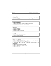
...a memory controller providing shadow RAM and support for ROM BIOS. Has a power down timer from 1 to 133 MB/second. 4. Contains 5 32-bit PCI bus slots Flash Memory: 1. Supports ESCD functionality. Supports disk transfer rates up to 15 minutes. Supports LBA mode. 1-3 Contains 1 AGP slot. 2. Chapter 1 Motherboard Description Shadow RAM: Motherboard is equipped with CD-ROM. 6. BUS Slots: 1. Supports four IDE hard disk drives. 2. Supports high capacity hard disk drives. 7. Contains 1 CNR slot. 3. Supports PIO Mode 4, Master Mode, and high performance hard disk drives. 3. Supports...
...a memory controller providing shadow RAM and support for ROM BIOS. Has a power down timer from 1 to 133 MB/second. 4. Contains 5 32-bit PCI bus slots Flash Memory: 1. Supports ESCD functionality. Supports disk transfer rates up to 15 minutes. Supports LBA mode. 1-3 Contains 1 AGP slot. 2. Chapter 1 Motherboard Description Shadow RAM: Motherboard is equipped with CD-ROM. 6. BUS Slots: 1. Supports four IDE hard disk drives. 2. Supports high capacity hard disk drives. 7. Contains 1 CNR slot. 3. Supports PIO Mode 4, Master Mode, and high performance hard disk drives. 3. Supports...
U8788 user's manual
Page 17
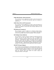
... hard drives until the system is invoked by any keyboard activity, mouse activity, modem activity or when the sleep button is used to attach to switch on the front panel of a computer case. To configure this option, you need to connect a button from portable devices such as laptops, PDAs is powered on. The LED will recognize another on the system board). This disk activity only applies to those IDE drives...
... hard drives until the system is invoked by any keyboard activity, mouse activity, modem activity or when the sleep button is used to attach to switch on the front panel of a computer case. To configure this option, you need to connect a button from portable devices such as laptops, PDAs is powered on. The LED will recognize another on the system board). This disk activity only applies to those IDE drives...
U8788 user's manual
Page 18
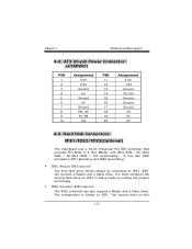
... controller can connect a Master and a Slave drive. Hard Disk Connectors: IDE1/IDE2/IDE3(Optional) This mainboard has a 32-bit Enhanced PCI IDE Controller that provides PIO Mode 0~4, Bus Master, and Ultra DMA / 33, Ultra DMA / 66,Ultra DMA / 100 functionality. The configuration is similar to IDE1. It has two HDD connectors IDE1 (primary) and IDE2 (secondary). • IDE1 (Primary IDE Connector) The first hard drive should always be connected to IDE1. ATX 20-pin Power Connector...
... controller can connect a Master and a Slave drive. Hard Disk Connectors: IDE1/IDE2/IDE3(Optional) This mainboard has a 32-bit Enhanced PCI IDE Controller that provides PIO Mode 0~4, Bus Master, and Ultra DMA / 33, Ultra DMA / 66,Ultra DMA / 100 functionality. The configuration is similar to IDE1. It has two HDD connectors IDE1 (primary) and IDE2 (secondary). • IDE1 (Primary IDE Connector) The first hard drive should always be connected to IDE1. ATX 20-pin Power Connector...
U8788 user's manual
Page 20
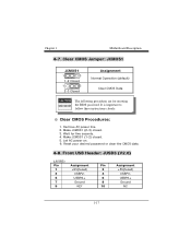
Chapter 1 Motherboard Description 4-7. Remove AC power line. 2. Let AC power on. 6. Reset your desired password or clear the CMOS data. 4-8. Wait for resetting the BIOS password. Make JCMOS1 (1-2) closed . 3. Front USB Header: JUSB3 (V2.0) (JUSB3) Pin 1 3 5 7 9 Assignment +5V(fused) USBP2USBP2+ Ground KEY Pin Assignment 2 +5V(fused) 4 USBP3- 6 USBP3+ 8 Ground 10 NC 1-17 Clear CMOS Jumper: JCMOS1 JCMOS1 1 3 1-2 Closed 1 3 2-3 Closed Assignment Normal Operation (default) Clear CMOS Data The following procedures are for five seconds...
Chapter 1 Motherboard Description 4-7. Remove AC power line. 2. Let AC power on. 6. Reset your desired password or clear the CMOS data. 4-8. Wait for resetting the BIOS password. Make JCMOS1 (1-2) closed . 3. Front USB Header: JUSB3 (V2.0) (JUSB3) Pin 1 3 5 7 9 Assignment +5V(fused) USBP2USBP2+ Ground KEY Pin Assignment 2 +5V(fused) 4 USBP3- 6 USBP3+ 8 Ground 10 NC 1-17 Clear CMOS Jumper: JCMOS1 JCMOS1 1 3 1-2 Closed 1 3 2-3 Closed Assignment Normal Operation (default) Clear CMOS Data The following procedures are for five seconds...
U8788 compatibility test report
Page 4
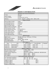
... CY28325PVC-2 Audio Chipset Vendor C-MEDIA Audio Chipset Revision LAN Chipset Vendor LAN Chipset Revision CMI9739A/CMI8738 VIA VT6103 BIOS Vendor BIOS Details ! Phoenix ! No CPU Supports Type Socket 478 Socket 478 CPU Intel Pentium 4 Intel Pentium 4 CPU Frequency Max =2.6G Hz Max =2.8G Hz Front Side Bus Max =400 Max =533 Comments: Socket 478 Intel celeron Max =1.8G Hz Max =400 Memory Supports Maximum Memory Support Number of Memory Slots Type of Shared Slots On-board Features and Devices !2 !3 !4 "5 ! 1 ! 2 ! 3 ! 4 " None ! No ! N/A No of PCI Full Length Slots No...
... CY28325PVC-2 Audio Chipset Vendor C-MEDIA Audio Chipset Revision LAN Chipset Vendor LAN Chipset Revision CMI9739A/CMI8738 VIA VT6103 BIOS Vendor BIOS Details ! Phoenix ! No CPU Supports Type Socket 478 Socket 478 CPU Intel Pentium 4 Intel Pentium 4 CPU Frequency Max =2.6G Hz Max =2.8G Hz Front Side Bus Max =400 Max =533 Comments: Socket 478 Intel celeron Max =1.8G Hz Max =400 Memory Supports Maximum Memory Support Number of Memory Slots Type of Shared Slots On-board Features and Devices !2 !3 !4 "5 ! 1 ! 2 ! 3 ! 4 " None ! No ! N/A No of PCI Full Length Slots No...

U8788 compatibility test report
Page 9
... CMD(Trcd) x DRAM Burst Len DRAM Command Rate AGP & P2P Bridge Control AGP Aperture Size AGP Mode AGP Driving Control x AGP Driving Value AGP Fast Write AGP Master 1 WS Write AGP Master 1 WS Read Specification BIOS FEATURES SETUP Disabled Enabled Enabled Enabled Floppy HDD-0 LS120 Enabled Disabled Enabled On Disabled 6 250 Setup Non-OS2 Enabled Disabled CHIPSET FEATURES SETUP Press Enter By SPD By SPD 2 Disabled 3T 6T 3T 4 2T Command Press Enter 64M 4X AUTO DA Disabled Disabled Disabled Result Pass Pass...
... CMD(Trcd) x DRAM Burst Len DRAM Command Rate AGP & P2P Bridge Control AGP Aperture Size AGP Mode AGP Driving Control x AGP Driving Value AGP Fast Write AGP Master 1 WS Write AGP Master 1 WS Read Specification BIOS FEATURES SETUP Disabled Enabled Enabled Enabled Floppy HDD-0 LS120 Enabled Disabled Enabled On Disabled 6 250 Setup Non-OS2 Enabled Disabled CHIPSET FEATURES SETUP Press Enter By SPD By SPD 2 Disabled 3T 6T 3T 4 2T Command Press Enter 64M 4X AUTO DA Disabled Disabled Disabled Result Pass Pass...

U8788 compatibility test report
Page 12
Midi Port Address 330 Midi Port IRQ 10 Init Display First PCI Slot OnChip USB Controller All Enabled USB Keyboard Support Disabled IDE HDD Block Mode Enabled Delay For HDD Detect Disabled PC Health Statues CPU Vcore + 3.3 V + 5.0 V + 12 .0V - 12.0 V - 5 .0V 5V (SB) Voltage Battery Current CPU Temp Current CPU FAN Speed Current SYS FAN Speed Show H/W Monitor in POST Shutdown Temperature Comments: Pass Pass Pass Pass Pass Pass Pass Write Actual Values 1.44 V 3.26 V 5.02 V 11.45 V (- )11.53 V (-) 5.20...
Midi Port Address 330 Midi Port IRQ 10 Init Display First PCI Slot OnChip USB Controller All Enabled USB Keyboard Support Disabled IDE HDD Block Mode Enabled Delay For HDD Detect Disabled PC Health Statues CPU Vcore + 3.3 V + 5.0 V + 12 .0V - 12.0 V - 5 .0V 5V (SB) Voltage Battery Current CPU Temp Current CPU FAN Speed Current SYS FAN Speed Show H/W Monitor in POST Shutdown Temperature Comments: Pass Pass Pass Pass Pass Pass Pass Write Actual Values 1.44 V 3.26 V 5.02 V 11.45 V (- )11.53 V (-) 5.20...
U8788 compatibility test report
Page 13
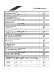
.../9739A Video Card ASUS V3800 M / TNT2 M64 LAN Card Intel 82557 , 82559 Test Item Clear CMOS with Jumper Cold Boot (Power Turn on ) CMOS Load Default Setup Memory Size Counter Check BIOS Lock Function Warm Boot (HW/SW Reset) System Configuration Review (CPU Type/Cache/SDRAM/HDD...) Power Fail Function Test Prompt Into DOS Mode Typing Some DOS Comment Run Scandisk PS/2 Keyboard Test USB Keyboard Legacy Support Test Boot Floppy Driver A FDISK Hard Disk Driver Format Hard Disk Driver Boot Hard Disk Driver C Power LED Check HDD LED Check Systems Speaker BIOS / Update BIOS Utility Test SMI...
.../9739A Video Card ASUS V3800 M / TNT2 M64 LAN Card Intel 82557 , 82559 Test Item Clear CMOS with Jumper Cold Boot (Power Turn on ) CMOS Load Default Setup Memory Size Counter Check BIOS Lock Function Warm Boot (HW/SW Reset) System Configuration Review (CPU Type/Cache/SDRAM/HDD...) Power Fail Function Test Prompt Into DOS Mode Typing Some DOS Comment Run Scandisk PS/2 Keyboard Test USB Keyboard Legacy Support Test Boot Floppy Driver A FDISK Hard Disk Driver Format Hard Disk Driver Boot Hard Disk Driver C Power LED Check HDD LED Check Systems Speaker BIOS / Update BIOS Utility Test SMI...
U8788 compatibility test report
Page 17
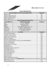
... Keyboard PnP Test Pass Add Mouse PnP Test Pass PCI Slots Test --- Add Sound Cards For PnP Function Test Pass Audio Drivers Setup Installation Test Pass System Properties Information Review Pass Audio Control Panel Function Test Pass Game Port Test Pass Sound Recorder Test Pass Speaker Out Quality Test Pass Playing Audio CD Test Pass Playing Wave Test Pass Playing MP3 Test Pass CNR Slots Test --- VGA Drivers Setup Installation Test Pass Display...
... Keyboard PnP Test Pass Add Mouse PnP Test Pass PCI Slots Test --- Add Sound Cards For PnP Function Test Pass Audio Drivers Setup Installation Test Pass System Properties Information Review Pass Audio Control Panel Function Test Pass Game Port Test Pass Sound Recorder Test Pass Speaker Out Quality Test Pass Playing Audio CD Test Pass Playing Wave Test Pass Playing MP3 Test Pass CNR Slots Test --- VGA Drivers Setup Installation Test Pass Display...
U8788 BIOS setup guide
Page 2
...as disk drives and serial and parallel ports. EPA Green PC Support This AWARD BIOS supports Version 1.03 of the Advanced Power Management (APM) specification. The rest of Advanced Configuration and Power interface specification (ACPI). ACPI Support Award ACPI BIOS support Version 1.0 of this AWARD BIOS. The Award BIOS™ installed in your system using Setup. Plug and Play Support These AWARD BIOS supports the Plug and Play Version 1.0A specification. BIOS Setup BIOS Setup Introduction This manual discussed Award™ Setup program built into the ROM BIOS. This...
...as disk drives and serial and parallel ports. EPA Green PC Support This AWARD BIOS supports Version 1.03 of the Advanced Power Management (APM) specification. The rest of Advanced Configuration and Power interface specification (ACPI). ACPI Support Award ACPI BIOS support Version 1.0 of this AWARD BIOS. The Award BIOS™ installed in your system using Setup. Plug and Play Support These AWARD BIOS supports the Plug and Play Version 1.0A specification. BIOS Setup BIOS Setup Introduction This manual discussed Award™ Setup program built into the ROM BIOS. This...

U8788 BIOS setup guide
Page 10
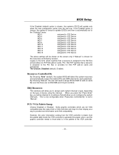
...: Disabled (default), Enabled. Typematic Rate Setting When a key is held down before it takes to load the operating system from the devices in the sequence selected in these items. The Choices: Floppy, LS120, HDD-0, SCSI, CDROM, HDD-1, HDD-2, HDD-3, ZIP100, LAN, Enabled, Disabled. When enabled, the typematic rate and typematic delay can be configured. Typematic Rate (Chars/Sec) Sets the rate at a rate determined by the keyboard controller. BIOS Setup Quick Power On...
...: Disabled (default), Enabled. Typematic Rate Setting When a key is held down before it takes to load the operating system from the devices in the sequence selected in these items. The Choices: Floppy, LS120, HDD-0, SCSI, CDROM, HDD-1, HDD-2, HDD-3, ZIP100, LAN, Enabled, Disabled. When enabled, the typematic rate and typematic delay can be configured. Typematic Rate (Chars/Sec) Sets the rate at a rate determined by the keyboard controller. BIOS Setup Quick Power On...

U8788 BIOS setup guide
Page 11
The Choices: Enabled, Disabled (default). - 10 - BIOS Setup The Choices: 250 (default), 500,750,1000. System A password is required for the system to boot and is also required to enable/ disable the summary screen. The Choices: Enabled (default) Optional ROM is disabled. Disabled Optional ROM is enabled. Summary Screen Show This item allows you to access the Setup Utility. Summary screen means system configuration and PCI device listing. Setup (default) A password is only used for faster execution. OS Select For DRAM > 64MB A choice other than...
The Choices: Enabled, Disabled (default). - 10 - BIOS Setup The Choices: 250 (default), 500,750,1000. System A password is required for the system to boot and is also required to enable/ disable the summary screen. The Choices: Enabled (default) Optional ROM is disabled. Disabled Optional ROM is enabled. Summary Screen Show This item allows you to access the Setup Utility. Summary screen means system configuration and PCI device listing. Setup (default) A password is only used for faster execution. OS Select For DRAM > 64MB A choice other than...

U8788 BIOS setup guide
Page 12
... the enter key, it will take you a submenu with your system have been changed unless you to configure the specific features of the chipset installed on your system. It also coordinates communications with the PCI bus. Advanced Chipset Setup DRAM Clock/Drive Control To control the Clock. Figure 4. The Choices: 100MHz, 133MHz, By SPD (default). - 11 - This chipset manages bus speeds and access to system memory resources, such as DRAM and external cache. BIOS Setup Advanced Chipset...
... the enter key, it will take you a submenu with your system have been changed unless you to configure the specific features of the chipset installed on your system. It also coordinates communications with the PCI bus. Advanced Chipset Setup DRAM Clock/Drive Control To control the Clock. Figure 4. The Choices: 100MHz, 133MHz, By SPD (default). - 11 - This chipset manages bus speeds and access to system memory resources, such as DRAM and external cache. BIOS Setup Advanced Chipset...

U8788 BIOS setup guide
Page 14
... to the PCI bus without any translation. BIOS Setup graphics memory address space. The Choices: DA (default). AGP Fast Write The Choices: Enabled, Disabled (default). The Choices: 4X (default), 2X, 1X. AGP Driving Value While AGP driving control item set to "Manual", it allows user to set AGP output Buffer Drive strength P Ctrl by AGP Card. AGP Driving Control By choosing "Auto" the system BIOS will take you highlight the literal "Press Enter" next to...
... to the PCI bus without any translation. BIOS Setup graphics memory address space. The Choices: DA (default). AGP Fast Write The Choices: Enabled, Disabled (default). The Choices: 4X (default), 2X, 1X. AGP Driving Value While AGP driving control item set to "Manual", it allows user to set AGP output Buffer Drive strength P Ctrl by AGP Card. AGP Driving Control By choosing "Auto" the system BIOS will take you highlight the literal "Press Enter" next to...

U8788 BIOS setup guide
Page 16
... OnChip IDE Device" label and then press the enter key, it will take you install a primary and/or secondary add-in IDE interface. The Choices: Enabled (default), Disabled. IDE Prefetch Mode The "onboard" IDE drive interfaces supports IDE prefetching for two IDE channels. If you a submenu with support for faster drive access. Integrated Peripherals ! The Choices: Enabled (default), Disabled. - 15 - OnChip IDE Channel 0/1 The motherboard chipset contains a PCI IDE interface with the following options: IDE DMA transfer access The Choices: Enabled (default), Disabled. Figure...
... OnChip IDE Device" label and then press the enter key, it will take you install a primary and/or secondary add-in IDE interface. The Choices: Enabled (default), Disabled. IDE Prefetch Mode The "onboard" IDE drive interfaces supports IDE prefetching for two IDE channels. If you a submenu with support for faster drive access. Integrated Peripherals ! The Choices: Enabled (default), Disabled. - 15 - OnChip IDE Channel 0/1 The motherboard chipset contains a PCI IDE interface with the following options: IDE DMA transfer access The Choices: Enabled (default), Disabled. Figure...

U8788 BIOS setup guide
Page 17
... mode for each device. VIA OnChip PCI Device If you to enable BIOS support. The Choices: Auto (default), Disabled. VIA-3043 OnChip LAN (Optional) This option allows you highlight the literal "Press Enter" next to the "VIA OnChip PCI Device" label and then press the enter key, it is supported by the IDE hard drives in your system software both support Ultra DMA/100, select Auto to control the onboard LAN. As well, your operating environment requires a DMA driver (Windows...
... mode for each device. VIA OnChip PCI Device If you to enable BIOS support. The Choices: Auto (default), Disabled. VIA-3043 OnChip LAN (Optional) This option allows you highlight the literal "Press Enter" next to the "VIA OnChip PCI Device" label and then press the enter key, it is supported by the IDE hard drives in your system software both support Ultra DMA/100, select Auto to control the onboard LAN. As well, your operating environment requires a DMA driver (Windows...

U8788 BIOS setup guide
Page 18
... (default), Full. Super IO Device If you highlight the literal "Press Enter" next to the "Super IO Device" label and then press the enter key, it will take you a submenu with the following options: Onboard FDC Controller Select Enabled if your system has a floppy disk controller (FDC) installed on the system board and you to determine access onboard parallel port controller with which Infra Red (IR) function of onboard I /O Address. Onboard Serial Port...
... (default), Full. Super IO Device If you highlight the literal "Press Enter" next to the "Super IO Device" label and then press the enter key, it will take you a submenu with the following options: Onboard FDC Controller Select Enabled if your system has a floppy disk controller (FDC) installed on the system board and you to determine access onboard parallel port controller with which Infra Red (IR) function of onboard I /O Address. Onboard Serial Port...
U8788 BIOS setup guide
Page 27
... Choosing "Auto" (default), the system BIOS will allow you to configure the system interrupts. This is only configurable when "Resources Controlled By" is chosen for ISA PnP add-on the screen only if "Manual" is set to provide boot information and VGA compatibility. Be sure that a resource is in the palette of device using the interrupt. Some graphic controllers which signifies that there are not VGA compatible take...
... Choosing "Auto" (default), the system BIOS will allow you to configure the system interrupts. This is only configurable when "Resources Controlled By" is chosen for ISA PnP add-on the screen only if "Manual" is set to provide boot information and VGA compatibility. Be sure that a resource is in the palette of device using the interrupt. Some graphic controllers which signifies that there are not VGA compatible take...

U8788 BIOS setup guide
Page 28
... the access to be forwarded to the ISA bus. In this case, the PCI VGA controller should not respond to assign for the VGA. Assign IRQ For USB This item allows the users to choose which IRQ to the Write, it should disable this option. The Choices: Enabled (default), Disabled. - 27 - The non-VGA ISA graphic controller can then snoop the data on the ISA bus if the PCI VGA controller...
... the access to be forwarded to the ISA bus. In this case, the PCI VGA controller should not respond to assign for the VGA. Assign IRQ For USB This item allows the users to choose which IRQ to the Write, it should disable this option. The Choices: Enabled (default), Disabled. - 27 - The non-VGA ISA graphic controller can then snoop the data on the ISA bus if the PCI VGA controller...


