

U8768 user's manual
Page 2
...3-1. CPU Socket 478 Configuration Steps 9 3-2. Hard Disk Connectors: IDE1/IDE2 15 4-4. Wake On LAN Header: JWOL1 16 4-6. Clear CMOS Jumper: JCMOS1 16 4-7. Layout of Contents Notice 1 Mainboard Features 2 1. Jumpers, Headers & Connectors 12 4-1. Features Introduction 2 1-1. Front USB Header: JUSB3 17 4-8. Front USB Header: JUSB4 17 4-9. 5V / 5VSB Selection for KB: JKBV1 17 i Package Contents 6 2. Front Panel Connector: JPANEL1 13 4-2. ATX 20-pin Power Connector: JATXPWR1 15 4-3. Component Index 8 3. System Fan Header: JSFAN1 11 4. Floppy Disk Connector...
...3-1. CPU Socket 478 Configuration Steps 9 3-2. Hard Disk Connectors: IDE1/IDE2 15 4-4. Wake On LAN Header: JWOL1 16 4-6. Clear CMOS Jumper: JCMOS1 16 4-7. Layout of Contents Notice 1 Mainboard Features 2 1. Jumpers, Headers & Connectors 12 4-1. Features Introduction 2 1-1. Front USB Header: JUSB3 17 4-8. Front USB Header: JUSB4 17 4-9. 5V / 5VSB Selection for KB: JKBV1 17 i Package Contents 6 2. Front Panel Connector: JPANEL1 13 4-2. ATX 20-pin Power Connector: JATXPWR1 15 4-3. Component Index 8 3. System Fan Header: JSFAN1 11 4. Floppy Disk Connector...
U8768 user's manual
Page 6
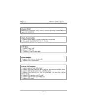
...Modes. 5.Supports IDE interface with a memory controller providing shadow RAM and support for ROM BIOS. Contains 3 32-bit PCI bus slots Flash Memory: 1.Supports flash memory functionality. 2.Supports ESCD functionality. BUS Slots: 1.Contains 1 AGP slot. 2.Contains 1 CNR slot. 3. Built in IDE Facilities: 1.Supports four IDE hard disk drives. 2.Supports PIO Mode 4, Master Mode, and high performance hard disk drives. 3.Supports disk transfer rates up to 15 minutes. Chapter 1 Motherboard Description Shadow RAM: Motherboard is equipped with CD-ROM. 6.Supports high capacity hard disk drives...
...Modes. 5.Supports IDE interface with a memory controller providing shadow RAM and support for ROM BIOS. Contains 3 32-bit PCI bus slots Flash Memory: 1.Supports flash memory functionality. 2.Supports ESCD functionality. BUS Slots: 1.Contains 1 AGP slot. 2.Contains 1 CNR slot. 3. Built in IDE Facilities: 1.Supports four IDE hard disk drives. 2.Supports PIO Mode 4, Master Mode, and high performance hard disk drives. 3.Supports disk transfer rates up to 15 minutes. Chapter 1 Motherboard Description Shadow RAM: Motherboard is equipped with CD-ROM. 6.Supports high capacity hard disk drives...
U8768 user's manual
Page 17
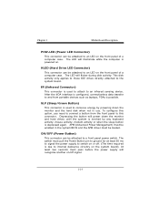
... (Power Button) This connector can be enabled in use. SLP (Sleep/Green Button) This connector is powered on. To configure this connector. The switch must pull the Power Button pin to ground for at least 50 ms to signal the power supply to switch on or off signal. 1-14 Chapter 1 Motherboard Description POW-LED (Power LED Connector) This connector can be attached to an LED on the front panel of a computer case. The LED will flicker during disk activity...
... (Power Button) This connector can be enabled in use. SLP (Sleep/Green Button) This connector is powered on. To configure this connector. The switch must pull the Power Button pin to ground for at least 50 ms to signal the power supply to switch on or off signal. 1-14 Chapter 1 Motherboard Description POW-LED (Power LED Connector) This connector can be attached to an LED on the front panel of a computer case. The LED will flicker during disk activity...
U8768 user's manual
Page 18
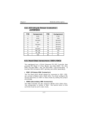
... has two HDD connectors IDE1 (primary) and IDE2 (secondary). • IDE1 (Primary IDE Connector) The first hard drive should always be set to Slave mode by setting the jumper accordingly. • IDE2 (Secondary IDE Connector) The IDE2 controller can connect a Master and a Slave drive. You must configure the second hard drive on this controller must be connected to IDE1. Hard Disk Connectors: IDE1/IDE2 This mainboard has a 32-bit Enhanced PCI IDE Controller that provides PIO Mode 0~4, Bus Master, and...
... has two HDD connectors IDE1 (primary) and IDE2 (secondary). • IDE1 (Primary IDE Connector) The first hard drive should always be set to Slave mode by setting the jumper accordingly. • IDE2 (Secondary IDE Connector) The IDE2 controller can connect a Master and a Slave drive. You must configure the second hard drive on this controller must be connected to IDE1. Hard Disk Connectors: IDE1/IDE2 This mainboard has a 32-bit Enhanced PCI IDE Controller that provides PIO Mode 0~4, Bus Master, and...
U8768 user's manual
Page 19
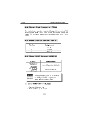
... (default) Clear CMOS Data The following procedures are for resetting the BIOS password. Make JCMOS1 (2-3) closed. 1-16 This connector supports the provided floppy drive ribbon cables. 4-5. Remove AC power line. 2. It is important to follow these instructions closely. ※ Clear CMOS Procedures: 1. Wake On LAN Header: JWOL1 Pin No. 1 2 3 Assignment 5V SB Ground Wake up 4-6. Chapter 1 Motherboard Description 4-4. Floppy Disk Connector: FDD1 The motherboard provides a standard floppy disk connector (FDC) that supports 360K, 720K, 1.2M, 1.44M and 2.88M floppy disk types.
... (default) Clear CMOS Data The following procedures are for resetting the BIOS password. Make JCMOS1 (2-3) closed. 1-16 This connector supports the provided floppy drive ribbon cables. 4-5. Remove AC power line. 2. It is important to follow these instructions closely. ※ Clear CMOS Procedures: 1. Wake On LAN Header: JWOL1 Pin No. 1 2 3 Assignment 5V SB Ground Wake up 4-6. Chapter 1 Motherboard Description 4-4. Floppy Disk Connector: FDD1 The motherboard provides a standard floppy disk connector (FDC) that supports 360K, 720K, 1.2M, 1.44M and 2.88M floppy disk types.
U8768 compatibility test report
Page 4
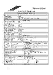
...-2 Audio Chipset Vendor C-Media Audio Chipset Revision LAN Chipset Vendor LAN Chipset Revision CMI9739A VIA VT6103 BIOS Vendor BIOS Details ! RIMM . ! PRODUCT INFORMATION Motherboard General Information Vendor Biostar Model Number Version Number Platform U8768 V1.1/V1.2 ! Phoenix ! None 4 SDRAM ! Yes " No No of PCI Full Length Slots No of ISA Full Length Slots AMR Slot Support CNR Slot Support ACR Slot Support Number of Memory Supported Parity Support ECC Support SDRAM 1024 (MB) " DIMM 2 . ! Others BIOS Revision Number BIOS Memory Size Flash EPROM BIOS...
...-2 Audio Chipset Vendor C-Media Audio Chipset Revision LAN Chipset Vendor LAN Chipset Revision CMI9739A VIA VT6103 BIOS Vendor BIOS Details ! RIMM . ! PRODUCT INFORMATION Motherboard General Information Vendor Biostar Model Number Version Number Platform U8768 V1.1/V1.2 ! Phoenix ! None 4 SDRAM ! Yes " No No of PCI Full Length Slots No of ISA Full Length Slots AMR Slot Support CNR Slot Support ACR Slot Support Number of Memory Supported Parity Support ECC Support SDRAM 1024 (MB) " DIMM 2 . ! Others BIOS Revision Number BIOS Memory Size Flash EPROM BIOS...

U8768 compatibility test report
Page 8
... CMD(Trcd) x DRAM Burst Len DRAM Command Rate AGP & P2P Bridge Control AGP Aperture Size AGP Mode AGP Driving Control x AGP Driving Value AGP Fast Write AGP Master 1 WS Write AGP Master 1 WS Read Specification BIOS FEATURES SETUP Disabled Enabled Enabled Enabled Floppy HDD-0 LS120 Enabled Disabled Enabled On Disabled 6 250 Setup Non-OS2 Enabled Disabled CHIPSET FEATURES SETUP Press Enter By SPD By SPD 2 Disabled 3T 6T 3T 4 2T Command Press Enter 64M 4X AUTO DA Disabled Disabled Disabled Result Pass Pass...
... CMD(Trcd) x DRAM Burst Len DRAM Command Rate AGP & P2P Bridge Control AGP Aperture Size AGP Mode AGP Driving Control x AGP Driving Value AGP Fast Write AGP Master 1 WS Write AGP Master 1 WS Read Specification BIOS FEATURES SETUP Disabled Enabled Enabled Enabled Floppy HDD-0 LS120 Enabled Disabled Enabled On Disabled 6 250 Setup Non-OS2 Enabled Disabled CHIPSET FEATURES SETUP Press Enter By SPD By SPD 2 Disabled 3T 6T 3T 4 2T Command Press Enter 64M 4X AUTO DA Disabled Disabled Disabled Result Pass Pass...

U8768 compatibility test report
Page 11
Midi Port Address 330 Midi Port IRQ 10 Init Display First PCI Slot OnChip USB Controller All Enabled USB Keyboard Support Disabled IDE HDD Block Mode Enabled Delay For HDD Detect Disabled PC Health Statues CPU Vcore + 3.3 V + 5.0 V + 12 .0V - 12.0 V - 5 .0V 5V (SB) Voltage Battery Current CPU Temp Current CPU FAN Speed Current SYS FAN Speed Show H/W Monitor in POST Shutdown Temperature Comments: Pass Pass Pass Pass Pass Pass Pass Write Actual Values 1.40V 3.18 V 4.99 V 11.71 V (- )11.70 V (-) 5.00...
Midi Port Address 330 Midi Port IRQ 10 Init Display First PCI Slot OnChip USB Controller All Enabled USB Keyboard Support Disabled IDE HDD Block Mode Enabled Delay For HDD Detect Disabled PC Health Statues CPU Vcore + 3.3 V + 5.0 V + 12 .0V - 12.0 V - 5 .0V 5V (SB) Voltage Battery Current CPU Temp Current CPU FAN Speed Current SYS FAN Speed Show H/W Monitor in POST Shutdown Temperature Comments: Pass Pass Pass Pass Pass Pass Pass Write Actual Values 1.40V 3.18 V 4.99 V 11.71 V (- )11.70 V (-) 5.00...
U8768 compatibility test report
Page 12
... CMI9739A Video Card LAN Card ELSA / 511TV /GEFORCE 2 Ti Intel 82557 , 82559 Test Item Clear CMOS with Jumper Cold Boot (Power Turn on ) CMOS Load Default Setup Memory Size Counter Check BIOS Lock Function Warm Boot (HW/SW Reset) System Configuration Review (CPU Type/Cache/SDRAM/HDD...) Power Fail Function Test Prompt Into DOS Mode Typing Some DOS Comment Run Scandisk PS/2 Keyboard Test USB Keyboard Legacy Support Test Boot Floppy Driver A FDISK Hard Disk Driver Format Hard Disk Driver Boot Hard Disk Driver C Power LED Check HDD LED Check Systems Speaker Buzz BIOS / Update BIOS Utility Test...
... CMI9739A Video Card LAN Card ELSA / 511TV /GEFORCE 2 Ti Intel 82557 , 82559 Test Item Clear CMOS with Jumper Cold Boot (Power Turn on ) CMOS Load Default Setup Memory Size Counter Check BIOS Lock Function Warm Boot (HW/SW Reset) System Configuration Review (CPU Type/Cache/SDRAM/HDD...) Power Fail Function Test Prompt Into DOS Mode Typing Some DOS Comment Run Scandisk PS/2 Keyboard Test USB Keyboard Legacy Support Test Boot Floppy Driver A FDISK Hard Disk Driver Format Hard Disk Driver Boot Hard Disk Driver C Power LED Check HDD LED Check Systems Speaker Buzz BIOS / Update BIOS Utility Test...

U8768 compatibility test report
Page 16
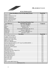
... VGA Resolution Test ( Monitor : ViewSonic GF775 /AGP: GF2 GTS Pro) --- Add SCSI Cards For PnP Function Test Pass Add Sound Card Test --- Add CNR Software Modem Card Test Pass Connect Performance Check Pass VGA Function Test --- Create Windows ME Startup Disk Pass Format 1.44 Floppy Driver Pass IDE Connectors Test --- Add Sound Cards For PnP Function Test Pass Audio Drivers Setup Installation Test Pass System Properties Information Review Pass Audio Control Panel Function Test Pass Game Port...
... VGA Resolution Test ( Monitor : ViewSonic GF775 /AGP: GF2 GTS Pro) --- Add SCSI Cards For PnP Function Test Pass Add Sound Card Test --- Add CNR Software Modem Card Test Pass Connect Performance Check Pass VGA Function Test --- Create Windows ME Startup Disk Pass Format 1.44 Floppy Driver Pass IDE Connectors Test --- Add Sound Cards For PnP Function Test Pass Audio Drivers Setup Installation Test Pass System Properties Information Review Pass Audio Control Panel Function Test Pass Game Port...

U8768 compatibility test report
Page 24
... Properties Information Review Pass Audio Control Panel Function Test Pass Game Port Test Pass Sound Recorder Test Pass Run MPG Files Pass Speaker Out Quality Test Pass Playing Audio CD Test Pass Playing Wave Test Pass Playing MIDI Test Pass Playing Video Test Pass Playing MP3 Test Pass CNR Slots Test --- Add SCSI Cards For PnP Function Test Pass Setup installation the Windows from Modem...
... Properties Information Review Pass Audio Control Panel Function Test Pass Game Port Test Pass Sound Recorder Test Pass Run MPG Files Pass Speaker Out Quality Test Pass Playing Audio CD Test Pass Playing Wave Test Pass Playing MIDI Test Pass Playing Video Test Pass Playing MP3 Test Pass CNR Slots Test --- Add SCSI Cards For PnP Function Test Pass Setup installation the Windows from Modem...
U8768 BIOS setup guide
Page 2
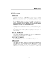
... standard devices such as disk drives and serial and parallel ports. The Setup program allows users to guide you through the process of configuring your computer system's ROM (Read Only Memory) is turned off. Sleep and Suspend power management modes are implemented via the System Management Interrupt (SMI). BIOS Setup BIOS Setup Introduction This manual discussed Award™ Setup program built into the ROM BIOS. This special information is then stored in your system using Setup. Plug...
... standard devices such as disk drives and serial and parallel ports. The Setup program allows users to guide you through the process of configuring your computer system's ROM (Read Only Memory) is turned off. Sleep and Suspend power management modes are implemented via the System Management Interrupt (SMI). BIOS Setup BIOS Setup Introduction This manual discussed Award™ Setup program built into the ROM BIOS. This special information is then stored in your system using Setup. Plug...

U8768 BIOS setup guide
Page 10
... version of the Power On Self-Test (POST) to execute after power on. Disabling this option allows you to load the operating system from the devices in the sequence selected in these items. The Choices: Floppy, LS120, HDD-0, SCSI, CDROM, HDD-1, HDD-2, HDD-3, ZIP100, LAN, Enabled, Disabled. State after you hold the key down. Typematic Rate (Chars/Sec) Sets the rate at a rate determined by the keyboard controller. The Choices: Enabled (default), Disabled...
... version of the Power On Self-Test (POST) to execute after power on. Disabling this option allows you to load the operating system from the devices in the sequence selected in these items. The Choices: Floppy, LS120, HDD-0, SCSI, CDROM, HDD-1, HDD-2, HDD-3, ZIP100, LAN, Enabled, Disabled. State after you hold the key down. Typematic Rate (Chars/Sec) Sets the rate at a rate determined by the keyboard controller. The Choices: Enabled (default), Disabled...

U8768 BIOS setup guide
Page 11
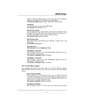
... for faster execution. Video BIOS Shadow Determines whether video BIOS will be copied to RAM for the system to boot and is also required to access the Setup Utility. Summary screen means system configuration and PCI device listing. Security Option This option will only apply if passwords are set from the Setup main menu. This will enable only individuals with memory exceeding 64MB. Disabled Optional ROM is enabled. Setup (default) A password is required to use the CMOS Setup Utility. The Choices: 250 (default), 500,750...
... for faster execution. Video BIOS Shadow Determines whether video BIOS will be copied to RAM for the system to boot and is also required to access the Setup Utility. Summary screen means system configuration and PCI device listing. Security Option This option will only apply if passwords are set from the Setup main menu. This will enable only individuals with memory exceeding 64MB. Disabled Optional ROM is enabled. Setup (default) A password is required to use the CMOS Setup Utility. The Choices: 250 (default), 500,750...

U8768 BIOS setup guide
Page 12
... default settings that the settings have been changed incorrectly. ! If you highlight the literal "Press Enter" next to the "DRAM Clock" label and then press the enter key, it will take you to system memory resources, such as DRAM and external cache. The Choices: 100MHz, 133MHz, By SPD (default). - 11 - Advanced Chipset Setup DRAM Clock/Drive Control To control the Clock. This chipset manages bus speeds and access to configure the specific features of the chipset installed on...
... default settings that the settings have been changed incorrectly. ! If you highlight the literal "Press Enter" next to the "DRAM Clock" label and then press the enter key, it will take you to system memory resources, such as DRAM and external cache. The Choices: 100MHz, 133MHz, By SPD (default). - 11 - Advanced Chipset Setup DRAM Clock/Drive Control To control the Clock. This chipset manages bus speeds and access to configure the specific features of the chipset installed on...
U8768 BIOS setup guide
Page 14
... AGP without interrupting the CPU. CPU & PCI Bus Control If you highlight the literal "Press Enter" next to the "CPU & PCI Bus Control" label and then press the enter key, it allows user to set AGP output Buffer Drive strength P Ctrl by AGP Card. The Choices: 4X (default), 2X, 1X. The Choices: Auto (default), Manual. The Choices: Disabled (default), Enabled. BIOS Setup graphics memory address space. Host cycles that it allows user to set to "Manual", it will the AGP...
... AGP without interrupting the CPU. CPU & PCI Bus Control If you highlight the literal "Press Enter" next to the "CPU & PCI Bus Control" label and then press the enter key, it allows user to set AGP output Buffer Drive strength P Ctrl by AGP Card. The Choices: 4X (default), 2X, 1X. The Choices: Auto (default), Manual. The Choices: Disabled (default), Enabled. BIOS Setup graphics memory address space. Host cycles that it allows user to set to "Manual", it will the AGP...
U8768 BIOS setup guide
Page 16
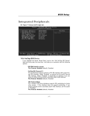
... BIOS Setup VIA OnChip IDE Device If you highlight the literal "Press Enter" next to "Disabled". The Choices: Enabled (default), Disabled. - 15 - Figure 5. If the interface does not support prefetching. Select "Disabled" to activate the first and/or second IDE interface. OnChip IDE Channel 0/1 The motherboard chipset contains a PCI IDE interface with the following options: IDE DMA transfer access The Choices: Enabled (default), Disabled. The Choices: Enabled (default), Disabled. IDE Prefetch Mode The "onboard" IDE drive interfaces supports IDE prefetching for two IDE channels...
... BIOS Setup VIA OnChip IDE Device If you highlight the literal "Press Enter" next to "Disabled". The Choices: Enabled (default), Disabled. - 15 - Figure 5. If the interface does not support prefetching. Select "Disabled" to activate the first and/or second IDE interface. OnChip IDE Channel 0/1 The motherboard chipset contains a PCI IDE interface with the following options: IDE DMA transfer access The Choices: Enabled (default), Disabled. The Choices: Enabled (default), Disabled. IDE Prefetch Mode The "onboard" IDE drive interfaces supports IDE prefetching for two IDE channels...
U8768 BIOS setup guide
Page 17
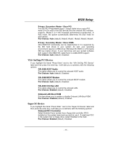
... options: Onboard FDC Controller Select Enabled if your system. The Choices: Enabled (default), Disabled. Super IO Device If you highlight the literal "Press Enter" next to use it is supported by the IDE hard drives in this field. If install and FDC or the system has no floppy drive, select Disabled in your system has a floppy disk controller (FDC) installed on the system board and you to enable or disable Onboard LAN Boot ROM. The Choices: Enabled (default), Disabled. - 16 - The Choices: Auto (default), Disabled...
... options: Onboard FDC Controller Select Enabled if your system. The Choices: Enabled (default), Disabled. Super IO Device If you highlight the literal "Press Enter" next to use it is supported by the IDE hard drives in this field. If install and FDC or the system has no floppy drive, select Disabled in your system has a floppy disk controller (FDC) installed on the system board and you to enable or disable Onboard LAN Boot ROM. The Choices: Enabled (default), Disabled. - 16 - The Choices: Auto (default), Disabled...
U8768 BIOS setup guide
Page 26
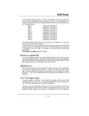
... signifies that will update only when the new configuration varies from a VGA controller and map it to their display as a way to provide boot information and VGA compatibility. Legacy is the term, which are no IRQ/DMA and I/O port conflicts. BIOS Setup If the Disabled (default) option is assigned to the ISA Bus and provides non-PnP ISA add-on cards. PCI / VGA Palette Snoop Choose Disabled or Enabled. However, the...
... signifies that will update only when the new configuration varies from a VGA controller and map it to their display as a way to provide boot information and VGA compatibility. Legacy is the term, which are no IRQ/DMA and I/O port conflicts. BIOS Setup If the Disabled (default) option is assigned to the ISA Bus and provides non-PnP ISA add-on cards. PCI / VGA Palette Snoop Choose Disabled or Enabled. However, the...

U8768 BIOS setup guide
Page 27
... Choices: Enabled (default), Disabled. - 26 - The Choices: Enabled (default), Disabled. Assign IRQ For USB This item allows the users to choose which IRQ to assign for the VGA. The non-VGA ISA graphic controller can then snoop the data on the ISA bus if the PCI VGA controller responds to the Write. BIOS Setup To do this case, the PCI VGA controller should not respond to the Write, it should disable this option. Unless...
... Choices: Enabled (default), Disabled. - 26 - The Choices: Enabled (default), Disabled. Assign IRQ For USB This item allows the users to choose which IRQ to assign for the VGA. The non-VGA ISA graphic controller can then snoop the data on the ISA bus if the PCI VGA controller responds to the Write. BIOS Setup To do this case, the PCI VGA controller should not respond to the Write, it should disable this option. Unless...


