
U8668 Pro user's manual
Page 4
U8668 Pro Features: 1.Contains on board I/O facilities that include a serial port, a VGA port, a parallel port, a PS/2 mouse port, a PS/2 keyboard port, audio ports, USB ports and a game ... form factor specifications. 4.Supports popular operating systems such as hard disks and CD-ROM Drives. 3.Supports the Intel Pentium ® 4 processor, a leading edge processor. Chapter 1 Motherboard Description Notice Introduction of system This mainboard is designed to take advantage of its predecessors, this mainboard continues a commitment to provide you with the ultimate...
U8668 Pro Features: 1.Contains on board I/O facilities that include a serial port, a VGA port, a parallel port, a PS/2 mouse port, a PS/2 keyboard port, audio ports, USB ports and a game ... form factor specifications. 4.Supports popular operating systems such as hard disks and CD-ROM Drives. 3.Supports the Intel Pentium ® 4 processor, a leading edge processor. Chapter 1 Motherboard Description Notice Introduction of system This mainboard is designed to take advantage of its predecessors, this mainboard continues a commitment to provide you with the ultimate...
U8668 Pro user's manual
Page 5
Chapter 1 Motherboard Description Mainboard Features 1. Hardware CPU: 1.Provides Socket-478. 2.Supports the Intel Pentium ® 4 processor providing the new generation power for x8 and 16 devices. 3.The ...
Chapter 1 Motherboard Description Mainboard Features 1. Hardware CPU: 1.Provides Socket-478. 2.Supports the Intel Pentium ® 4 processor providing the new generation power for x8 and 16 devices. 3.The ...

U8668 Pro user's manual
Page 6
... slots Fast EtherNet 10/ 100 1-Port PHY/ Transceiver: 1.Dual Speed - 100/ 10 Mbps. 2.Half and Full Duplex. 3.MII Interface to 15 minutes. Chapter 1 Motherboard Description Shadow RAM: Motherboard is equipped with Monitor Power 3 Green Functionality: 1.Supports Award BIOS ™ power management functionality. 2.Has a power down timer from 1 to Ethernet Controller. 4.Optional Repeater...
... slots Fast EtherNet 10/ 100 1-Port PHY/ Transceiver: 1.Dual Speed - 100/ 10 Mbps. 2.Half and Full Duplex. 3.MII Interface to 15 minutes. Chapter 1 Motherboard Description Shadow RAM: Motherboard is equipped with Monitor Power 3 Green Functionality: 1.Supports Award BIOS ™ power management functionality. 2.Has a power down timer from 1 to Ethernet Controller. 4.Optional Repeater...

U8668 Pro user's manual
Page 7
.... 3. Full internal AGP 4x performance. 8. High quality DVD video playback. 11. 2D / 3D resolutions up to 1920x1440. 4. 3D Rendering Features 1. Massive 2K x 2K textures. 8. Chapter 1 Motherboard Description Management protocols. 3.I2C Serial Bus for DDC Monitor Communications. 2. 2D Hardware Acceleration Features 1. Floating-point triangle setup engine. 4. Single circle 128-bit 3D architecture...
.... 3. Full internal AGP 4x performance. 8. High quality DVD video playback. 11. 2D / 3D resolutions up to 1920x1440. 4. 3D Rendering Features 1. Massive 2K x 2K textures. 8. Chapter 1 Motherboard Description Management protocols. 3.I2C Serial Bus for DDC Monitor Communications. 2. 2D Hardware Acceleration Features 1. Floating-point triangle setup engine. 4. Single circle 128-bit 3D architecture...

U8668 Pro user's manual
Page 8
... ADC, DACs. 4.SNR>95 Bb throughmixer and DAC. Enhanced Parallel Port (EPP). Hardware Monitor Function: 1.Monitors CPU Fan Speed. 2.Monitors System Voltage. 3.Monitors System Speed. Motherboard Description AC'97 Sound Codec Onboard: 1.AC-LINK protocol comfliance. 2.Compliant with CD-ROM. 6.Supports high capacity hard disk drives. 7.Supports LBA mode. I/O facilities: 1.One...
... ADC, DACs. 4.SNR>95 Bb throughmixer and DAC. Enhanced Parallel Port (EPP). Hardware Monitor Function: 1.Monitors CPU Fan Speed. 2.Monitors System Voltage. 3.Monitors System Speed. Motherboard Description AC'97 Sound Codec Onboard: 1.AC-LINK protocol comfliance. 2.Compliant with CD-ROM. 6.Supports high capacity hard disk drives. 7.Supports LBA mode. I/O facilities: 1.One...

U8668 Pro user's manual
Page 9
Operating System: Offers the highest performance for MATX Case (Optional). 6.Fully Setup Driver CD. 6 Package Contents 1.HDD Cable. 2.FDD Cable. 3.Flash Memory Writer for BIOS Update. 4.USB Cable (Optional). 5.Rear I/O Panel for MS-DOS, Windows NT, Windows 2000, Windows ME, Windows XP, Novell, LINUX, and SCO UNIX etc. 1-3. Chapter 1 Motherboard Description 1-2. BIOS & Software 1.Award legal BIOS. 2.Supports APM1.2. 3.Supports USB Function. 4.Supports ACPI.
Operating System: Offers the highest performance for MATX Case (Optional). 6.Fully Setup Driver CD. 6 Package Contents 1.HDD Cable. 2.FDD Cable. 3.Flash Memory Writer for BIOS Update. 4.USB Cable (Optional). 5.Rear I/O Panel for MS-DOS, Windows NT, Windows 2000, Windows ME, Windows XP, Novell, LINUX, and SCO UNIX etc. 1-3. Chapter 1 Motherboard Description 1-2. BIOS & Software 1.Award legal BIOS. 2.Supports APM1.2. 3.Supports USB Function. 4.Supports ACPI.
U8668 Pro user's manual
Page 10
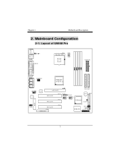
Layout of U8668 Pro JKBMS1 K/B & Mouse JUSBLAN USB & LAN JCOM1 JPRNT1 CPU1 Socket 478 CPU JATXPWR1 COM1 Parallel Port VGA1 PRIMARY IDE CONN. Chapter 1 Motherboard Description 2. Game Port In Out MIC Line Speaker JVGA1 JATXPWR2 P4M266 (VT8751) In Codec 1 JCDIN1 BIOS FLOPPY DISK CONN. SECONDARY IDE CONN. LAN AGP SLOT IDE1 IDE2 PCI SLOT PCI SLOT PCI1 PCI2 JUSBV3 1 1 JUSBV4 2 10 2 10 1 91 9 JUSB3 JUSB4 B AT 1 VT8235 1 JCMOS1 FDD1 PCI3 PCI SLOT CNR1 CNR SLOT JWOL1 1 ITE I/O JPANEL1 2 24 1 23 7 Mainboard Configuration 2-1.
Layout of U8668 Pro JKBMS1 K/B & Mouse JUSBLAN USB & LAN JCOM1 JPRNT1 CPU1 Socket 478 CPU JATXPWR1 COM1 Parallel Port VGA1 PRIMARY IDE CONN. Chapter 1 Motherboard Description 2. Game Port In Out MIC Line Speaker JVGA1 JATXPWR2 P4M266 (VT8751) In Codec 1 JCDIN1 BIOS FLOPPY DISK CONN. SECONDARY IDE CONN. LAN AGP SLOT IDE1 IDE2 PCI SLOT PCI SLOT PCI1 PCI2 JUSBV3 1 1 JUSBV4 2 10 2 10 1 91 9 JUSB3 JUSB4 B AT 1 VT8235 1 JCMOS1 FDD1 PCI3 PCI SLOT CNR1 CNR SLOT JWOL1 1 ITE I/O JPANEL1 2 24 1 23 7 Mainboard Configuration 2-1.
U8668 Pro user's manual
Page 11
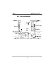
Component Index Socket 478 CPU BIOS Codec LAN P4M266 (VT8751) B AT1 VT8235 ITE I/O 8 Chapter 1 Motherboard Description 2-2.
Component Index Socket 478 CPU BIOS Codec LAN P4M266 (VT8751) B AT1 VT8235 ITE I/O 8 Chapter 1 Motherboard Description 2-2.
U8668 Pro user's manual
Page 12
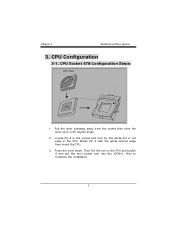
CPU Configuration 3-1. CPU Socket 478 Configuration Steps: CPU Fan CPU 1. Then Put the fan on the CPU and buckle it and put the fan's power port into the JCFAN1, then to a 90-degree angle. 2. Locate Pin A in the socket and look for the white dot or cut edge then insert the CPU. 3. Pull the lever sideways away from the socket then raise the lever up to complete the installation. 9 Chapter 1 Motherboard Description 3. Match Pin A with the white dot/cut edge in the CPU. Press the lever down.
CPU Configuration 3-1. CPU Socket 478 Configuration Steps: CPU Fan CPU 1. Then Put the fan on the CPU and buckle it and put the fan's power port into the JCFAN1, then to a 90-degree angle. 2. Locate Pin A in the socket and look for the white dot or cut edge then insert the CPU. 3. Pull the lever sideways away from the socket then raise the lever up to complete the installation. 9 Chapter 1 Motherboard Description 3. Match Pin A with the white dot/cut edge in the CPU. Press the lever down.
U8668 Pro user's manual
Page 13
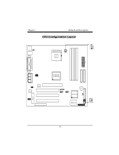
Chapter 1 Motherboard Description CPU Configuration Layout Socket 478 CPU BIOS Codec LAN P4M266 (VT8751) BAT1 VT8235 ITE I/O JSFAN1 10
Chapter 1 Motherboard Description CPU Configuration Layout Socket 478 CPU BIOS Codec LAN P4M266 (VT8751) BAT1 VT8235 ITE I/O JSFAN1 10
U8668 Pro user's manual
Page 14
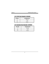
System Fan Header: JSFAN1 Pin No. 1 2 3 Assignment Ground +12V Sense 11 Chapter 1 Motherboard Description 3-2. CPU Fan Header: JCFAN1 Pin No. 1 2 3 Assignment Ground +12V Sense 3-3.
System Fan Header: JSFAN1 Pin No. 1 2 3 Assignment Ground +12V Sense 11 Chapter 1 Motherboard Description 3-2. CPU Fan Header: JCFAN1 Pin No. 1 2 3 Assignment Ground +12V Sense 3-3.
U8668 Pro user's manual
Page 15
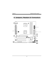
Chapter 1 Motherboard Description 4. Jumpers, Headers & Connectors 1 JKBV1 J AT X PW R 2 1 JUSBV3 Codec LAN BIOS 2 10 1 9 JUSB3 Socket 478 CPU J AT X PW R 1 P4M266 (VT8751) IDE Connectors (IDE1-2) BAT1 VT8235 ITE I/O 1 JUSBV4 JCMOS1 1 FDD1 JWOL1 1 JPANEL1 JUSB4 2 10 1 9 12
Chapter 1 Motherboard Description 4. Jumpers, Headers & Connectors 1 JKBV1 J AT X PW R 2 1 JUSBV3 Codec LAN BIOS 2 10 1 9 JUSB3 Socket 478 CPU J AT X PW R 1 P4M266 (VT8751) IDE Connectors (IDE1-2) BAT1 VT8235 ITE I/O 1 JUSBV4 JCMOS1 1 FDD1 JWOL1 1 JPANEL1 JUSB4 2 10 1 9 12
U8668 Pro user's manual
Page 16
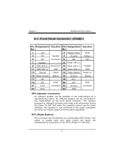
... 20 KEY IrDA 21 VCC5 Connector 22 Ground Connector 23 IRTX 24 IRRX SPK (Speaker Connector) An offboard speaker can be attached to the motherboard at the front panel connector. RST (Reset Button) This connector can be connected to a momentary SPST switch. This switch is not connected ...to reset and run the POST (Power On Self Test). 13 The speaker is usually open and when closed will cause the motherboard to the audio subsystem and does not receive output from the audio subsystem. The speaker (onboard or offboard) provides error beep code information...
... 20 KEY IrDA 21 VCC5 Connector 22 Ground Connector 23 IRTX 24 IRRX SPK (Speaker Connector) An offboard speaker can be attached to the motherboard at the front panel connector. RST (Reset Button) This connector can be connected to a momentary SPST switch. This switch is not connected ...to reset and run the POST (Power On Self Test). 13 The speaker is usually open and when closed will cause the motherboard to the audio subsystem and does not receive output from the audio subsystem. The speaker (onboard or offboard) provides error beep code information...
U8668 Pro user's manual
Page 17
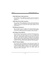
... connector is depressed again. HLED (Hard Drive LED Connector) This connector can be attached to an LED on the front panel of a computer case. Chapter 1 Motherboard Description POW-LED (Power LED Connector) This connector can be attached to an LED on the front panel of a computer case. Depressing the button will...
... connector is depressed again. HLED (Hard Drive LED Connector) This connector can be attached to an LED on the front panel of a computer case. Chapter 1 Motherboard Description POW-LED (Power LED Connector) This connector can be attached to an LED on the front panel of a computer case. Depressing the button will...

U8668 Pro user's manual
Page 18
... DMA / 33, Ultra DMA / 66,Ultra DMA / 100 functionality. IDE1 can also support a Master and a Slave drive. The second drive on IDE1 to IDE1. Chapter 1 Motherboard Description 4-2. You must configure the second hard drive on this controller must be connected to Slave mode by setting the jumper accordingly. • IDE2 (Secondary...
... DMA / 33, Ultra DMA / 66,Ultra DMA / 100 functionality. IDE1 can also support a Master and a Slave drive. The second drive on IDE1 to IDE1. Chapter 1 Motherboard Description 4-2. You must configure the second hard drive on this controller must be connected to Slave mode by setting the jumper accordingly. • IDE2 (Secondary...

U8668 Pro user's manual
Page 19
Floppy Disk Connector: FDD1 The motherboard provides a standard floppy disk connector (FDC) that supports 360K, 720K, 1.2M, 1.44M and 2.88M floppy disk types. It is important to follow these instructions closely. &#... supports the provided floppy drive ribbon cables. 4-5. Remove AC power line. 2. Wake On LAN Header: JWOL1 Pin No. 1 2 3 Assignment +5V SB Ground Wake up 4-6. Chapter 1 Motherboard Description 4-4.
Floppy Disk Connector: FDD1 The motherboard provides a standard floppy disk connector (FDC) that supports 360K, 720K, 1.2M, 1.44M and 2.88M floppy disk types. It is important to follow these instructions closely. &#... supports the provided floppy drive ribbon cables. 4-5. Remove AC power line. 2. Wake On LAN Header: JWOL1 Pin No. 1 2 3 Assignment +5V SB Ground Wake up 4-6. Chapter 1 Motherboard Description 4-4.

U8668 Pro user's manual
Page 20
... Make JCMOS1 (1-2) closed. 5. Front USB Header: JUSB3 (JUSB3) Pin 1 3 5 7 9 Assignment +5V(fused) USBP2USBP2+ Ground KEY Pin Assignment 2 +5V(fused) 4 USBP3- 6 USBP3+ 8 Ground 10 NC 4-8. Chapter 1 Motherboard Description 3. Let AC power on. 6. Front USB Header: JUSB4 (JUSB4) Pin 1 3 5 7 9 Assignment +5V(fused) USBP2USBP2+ Ground KEY Pin Assignment 2 +5V(fused) 4 USBP3- 6 USBP3+ 8 Ground 10...
... Make JCMOS1 (1-2) closed. 5. Front USB Header: JUSB3 (JUSB3) Pin 1 3 5 7 9 Assignment +5V(fused) USBP2USBP2+ Ground KEY Pin Assignment 2 +5V(fused) 4 USBP3- 6 USBP3+ 8 Ground 10 NC 4-8. Chapter 1 Motherboard Description 3. Let AC power on. 6. Front USB Header: JUSB4 (JUSB4) Pin 1 3 5 7 9 Assignment +5V(fused) USBP2USBP2+ Ground KEY Pin Assignment 2 +5V(fused) 4 USBP3- 6 USBP3+ 8 Ground 10...
U8668 Pro user's manual
Page 21
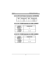
Chapter 1 Motherboard Description 4-10. ATX 12V Power Connector: JATXPWR2 PIN 1 2 Assignment +12V +12V PIN 3 4 Assignment Ground Ground 4-11. 5V / 5VSB Selection for USB: JUSBV3 JUSBV3 1 3 1-2 Closed 1 3 2-3 Closed Assignment 5V 5V_SB 4-12. 5V / 5VSB Selection for USB: JUSBV4 JUSBV4 1 3 1-2 Closed 1 3 2-3 Closed Assignment 5V 5V_SB 18
Chapter 1 Motherboard Description 4-10. ATX 12V Power Connector: JATXPWR2 PIN 1 2 Assignment +12V +12V PIN 3 4 Assignment Ground Ground 4-11. 5V / 5VSB Selection for USB: JUSBV3 JUSBV3 1 3 1-2 Closed 1 3 2-3 Closed Assignment 5V 5V_SB 4-12. 5V / 5VSB Selection for USB: JUSBV4 JUSBV4 1 3 1-2 Closed 1 3 2-3 Closed Assignment 5V 5V_SB 18
U8668 Pro user's manual
Page 22
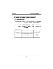
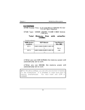
DRAM Type: 128MB/ 256MB/ 512MB/ 1GB DIMM Module (184 pin) Total Memory Size with unbuffer DIMMs (Only for reference) DIMM Socket Location DDR Module Total Memory Size (MB) DDR 1 64MB/128MB/256MB/512MB/1GB *1 Max is DDR 2 64MB/128MB/256MB/512MB/1GB 2GB *1 19 Chapter 1 Motherboard Description 5. RAM Module Configuration 5-1. DDR SDRAM DRAM Access Time: 2.5V Unbuffered DDR SDRAM PC1600/ PC2100 Type required.
DRAM Type: 128MB/ 256MB/ 512MB/ 1GB DIMM Module (184 pin) Total Memory Size with unbuffer DIMMs (Only for reference) DIMM Socket Location DDR Module Total Memory Size (MB) DDR 1 64MB/128MB/256MB/512MB/1GB *1 Max is DDR 2 64MB/128MB/256MB/512MB/1GB 2GB *1 19 Chapter 1 Motherboard Description 5. RAM Module Configuration 5-1. DDR SDRAM DRAM Access Time: 2.5V Unbuffered DDR SDRAM PC1600/ PC2100 Type required.
U8668 Pro user's manual
Page 23
... automatically set to 2.5V. !When you can only use DDR SDRAM, the memory power will automatically set to insert both kind of memory on this motherboard. Chapter 1 Motherboard Description 5-2 SDRAM DRAM Access Time: 3.3V Unbuffered SDRAM PC100/ PC133 Type required.
... automatically set to 2.5V. !When you can only use DDR SDRAM, the memory power will automatically set to insert both kind of memory on this motherboard. Chapter 1 Motherboard Description 5-2 SDRAM DRAM Access Time: 3.3V Unbuffered SDRAM PC100/ PC133 Type required.

