

MOTHER BOARD MANUAL
Page 2
Table of Contents Chapter 1: Introduction 3 1.1 Before You Start 3 1.2 Package Checklist 3 1.3 Motherboard Features 4 1.4 Rear Panel Connectors 6 1.5 Motherboard Layout 7 Chapter 2: Hardware Installation 8 2.1 Installing Central Processing Unit (CPU 8 2.2 FAN Headers 10 2.3 Installing System Memory 11 2.4 Connectors and Slots 13 Chapter 3: Headers & Jumpers Setup 15 3.1 ...
Table of Contents Chapter 1: Introduction 3 1.1 Before You Start 3 1.2 Package Checklist 3 1.3 Motherboard Features 4 1.4 Rear Panel Connectors 6 1.5 Motherboard Layout 7 Chapter 2: Hardware Installation 8 2.1 Installing Central Processing Unit (CPU 8 2.2 FAN Headers 10 2.3 Installing System Memory 11 2.4 Connectors and Slots 13 Chapter 3: Headers & Jumpers Setup 15 3.1 ...

MOTHER BOARD MANUAL
Page 3
...flex the board. „ Do not leave any unfastened small parts inside the case after installation. Before you start installing the motherboard, please make sure you follow the instructions below: „ Prepare a dry and stable working environment with sufficient lighting. „...equipment. „ Keep the computer from anti-static bag, ground yourself properly by area or your motherboard version. 3 CHAPTER 1: INTRODUCTION TF7150U-M7/TF7100P-M7 1.1 BEFORE YOU START Thank you take the motherboard out from dangerous area, such as heat source, humid air and water. 1.2 PACKAGE CHECKLIST HDD...
...flex the board. „ Do not leave any unfastened small parts inside the case after installation. Before you start installing the motherboard, please make sure you follow the instructions below: „ Prepare a dry and stable working environment with sufficient lighting. „...equipment. „ Keep the computer from anti-static bag, ground yourself properly by area or your motherboard version. 3 CHAPTER 1: INTRODUCTION TF7150U-M7/TF7100P-M7 1.1 BEFORE YOU START Thank you take the motherboard out from dangerous area, such as heat source, humid air and water. 1.2 PACKAGE CHECKLIST HDD...

MOTHER BOARD MANUAL
Page 4
... Half / Full duplex capability Half / Full duplex capability 4 SATA Version 2.0 specification compliant. Data transfer rates up to 3 Gb/s. Low Pin Count Interface Super I /O functionality. Motherboard Manual 1.3 MOTHERBOARD FEATURES TF7150U-M7 TF7100P-M7 LGA 775 LGA 775 Intel Core2Duo / Core2Quad / Celeron 4xx / Intel Core2Duo / Core2Quad / Celeron 4xx / Pentium D / Pentium 4 processor Pentium D / Pentium 4 processor Supports 45nm CPU...
... Half / Full duplex capability Half / Full duplex capability 4 SATA Version 2.0 specification compliant. Data transfer rates up to 3 Gb/s. Low Pin Count Interface Super I /O functionality. Motherboard Manual 1.3 MOTHERBOARD FEATURES TF7150U-M7 TF7100P-M7 LGA 775 LGA 775 Intel Core2Duo / Core2Quad / Celeron 4xx / Intel Core2Duo / Core2Quad / Celeron 4xx / Pentium D / Pentium 4 processor Pentium D / Pentium 4 processor Supports 45nm CPU...

MOTHER BOARD MANUAL
Page 6
... interface transmitting digital video signals to digital display devices such as a digital television. \ D-Sub VGA Port Transmit analog video signals to different display panels simultaneously. 6 Motherboard Manual 1.4 REAR PANEL CONNECTORS X PS/2 Keyboard Port Y USB 2.0 Port x 2 Z DVI-D VGA Port The Digital Visual Interface (DVI) is an all-digital audio/video interface capable...
... interface transmitting digital video signals to digital display devices such as a digital television. \ D-Sub VGA Port Transmit analog video signals to different display panels simultaneously. 6 Motherboard Manual 1.4 REAR PANEL CONNECTORS X PS/2 Keyboard Port Y USB 2.0 Port x 2 Z DVI-D VGA Port The Digital Visual Interface (DVI) is an all-digital audio/video interface capable...
MOTHER BOARD MANUAL
Page 7
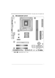
JVGA1 1.5 MOTHERBOARD LAYOUT JUSBKB1 LGA775 JUSBV1 CPU1 TF7150U-M7/TF7100P-M7 JCFAN1 JATXPWR1 JDVI1 JHDMI DIMMA1 DIMMA2 JATXPWR2 IDE1 FDD1 JUSBLAN1 AUDIO1 JNFAN1 BIOS GeForce 7150/7100 nForce 630i PEX1_1 LAN PEX16_1 PCI1 Codec PCI2 JAUDIOF1 JCDIN1 JSPDIF_OUT1 JPRNT1 BAT1 RSTSW1 Super I/O SATA2 LED_D1 SATA4 LED_D2 JUSB2 JUSB3 JUSB4 JCOM1 PWRSW1 JUSBV2 SATA 1 SATA3 JSFAN1 JCMOS1 JPANEL1 Note: ■ represents the 1st pin. 7
JVGA1 1.5 MOTHERBOARD LAYOUT JUSBKB1 LGA775 JUSBV1 CPU1 TF7150U-M7/TF7100P-M7 JCFAN1 JATXPWR1 JDVI1 JHDMI DIMMA1 DIMMA2 JATXPWR2 IDE1 FDD1 JUSBLAN1 AUDIO1 JNFAN1 BIOS GeForce 7150/7100 nForce 630i PEX1_1 LAN PEX16_1 PCI1 Codec PCI2 JAUDIOF1 JCDIN1 JSPDIF_OUT1 JPRNT1 BAT1 RSTSW1 Super I/O SATA2 LED_D1 SATA4 LED_D2 JUSB2 JUSB3 JUSB4 JCOM1 PWRSW1 JUSBV2 SATA 1 SATA3 JSFAN1 JCMOS1 JPANEL1 Note: ■ represents the 1st pin. 7

MOTHER BOARD MANUAL
Page 8
When the CPU is removed, cover the Pin Cap on the empty socket to a 90-degree angle. 8 Motherboard Manual CHAPTER 2: HARDWARE INSTALLATION 2.1 INSTALLING CENTRAL PROCESSING UNIT (CPU) Special Notice: Remove Pin Cap before installation, and make good preservation for future use. Pin-Cap Step 1: Pull the socket locking lever out from the socket and then raise the lever up to ensure pin legs won't be damaged.
When the CPU is removed, cover the Pin Cap on the empty socket to a 90-degree angle. 8 Motherboard Manual CHAPTER 2: HARDWARE INSTALLATION 2.1 INSTALLING CENTRAL PROCESSING UNIT (CPU) Special Notice: Remove Pin Cap before installation, and make good preservation for future use. Pin-Cap Step 1: Pull the socket locking lever out from the socket and then raise the lever up to ensure pin legs won't be damaged.

MOTHER BOARD MANUAL
Page 10
Motherboard Manual 2.2 FAN HEADERS These fan headers support cooling-fans built in the computer. When connecting with wires onto connectors, please note that the red wire ...
Motherboard Manual 2.2 FAN HEADERS These fan headers support cooling-fans built in the computer. When connecting with wires onto connectors, please note that the red wire ...

MOTHER BOARD MANUAL
Page 12
Motherboard Manual 2. Memory Capacity DIMM Socket Location DIMMA1 DIMMA2 DDR2 Module 512MB/1024MB/2048MB 512MB/1024MB/2048MB Total Memory Size Max is properly seated. Insert the DIMM vertically and firmly into the slot until the retaining chip snap back in place and the DIMM is 4GB. 12 B.
Motherboard Manual 2. Memory Capacity DIMM Socket Location DIMMA1 DIMMA2 DDR2 Module 512MB/1024MB/2048MB 512MB/1024MB/2048MB Total Memory Size Max is properly seated. Insert the DIMM vertically and firmly into the slot until the retaining chip snap back in place and the DIMM is 4GB. 12 B.
MOTHER BOARD MANUAL
Page 13
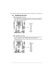
This connector supports the provided floppy drive ribbon cable. 34 33 2 1 IDE1: Hard Disk Connector The motherboard has a 32-bit Enhanced PCI IDE Controller that supports 360K, 720K, 1.2M, 1.44M and 2.88M floppy disk types. TF7150U-M7/TF7100P-M7 2.4 CONNECTORS AND SLOTS FDD1: Floppy Disk Connector The motherboard provides a standard floppy disk connector that provides PIO Mode 0~4, Bus Master, and Ultra DMA 33/66/100/133 functionality. The IDE connector can connect a master and a slave drive, so you can connect up to two IDE devices. 40 39 21 13
This connector supports the provided floppy drive ribbon cable. 34 33 2 1 IDE1: Hard Disk Connector The motherboard has a 32-bit Enhanced PCI IDE Controller that supports 360K, 720K, 1.2M, 1.44M and 2.88M floppy disk types. TF7150U-M7/TF7100P-M7 2.4 CONNECTORS AND SLOTS FDD1: Floppy Disk Connector The motherboard provides a standard floppy disk connector that provides PIO Mode 0~4, Bus Master, and Ultra DMA 33/66/100/133 functionality. The IDE connector can connect a master and a slave drive, so you can connect up to two IDE devices. 40 39 21 13

MOTHER BOARD MANUAL
Page 14
...rate of 8GB/s totally. This PCI slot is equipped with 2 standard PCI slots. Maximum theoretical realized bandwidth of 4GB/s simultaneously per direction; 500MB/s in total. - Motherboard Manual PEX16_1: PCI-Express x16 Slot - PCI-Express 1.0a compliant. - Data transfer bandwidth up to 250MB/s per direction, for expansion cards. PCI-Express 1.0a compliant... an aggregate of 2.5GB/s on the data pins. - 2X bandwidth over the traditional PCI architecture. PEX1_1 PEX16_1 PCI1~PCI2: Peripheral Component Interconnect Slots This motherboard is designated as 32 bits. PCI1 PCI2 14
...rate of 8GB/s totally. This PCI slot is equipped with 2 standard PCI slots. Maximum theoretical realized bandwidth of 4GB/s simultaneously per direction; 500MB/s in total. - Motherboard Manual PEX16_1: PCI-Express x16 Slot - PCI-Express 1.0a compliant. - Data transfer bandwidth up to 250MB/s per direction, for expansion cards. PCI-Express 1.0a compliant... an aggregate of 2.5GB/s on the data pins. - 2X bandwidth over the traditional PCI architecture. PEX1_1 PEX16_1 PCI1~PCI2: Peripheral Component Interconnect Slots This motherboard is designated as 32 bits. PCI1 PCI2 14

MOTHER BOARD MANUAL
Page 16
Motherboard Manual JATXPWR1: ATX Power Source Connector This connector allows user to connect 24-pin power connector on the ATX power supply. 12 24 Pin Assignment ...
Motherboard Manual JATXPWR1: ATX Power Source Connector This connector allows user to connect 24-pin power connector on the ATX power supply. 12 24 Pin Assignment ...

MOTHER BOARD MANUAL
Page 18
Motherboard Manual JCDIN1: CD-ROM Audio-in Connector This connector allows user to connect the audio source from the variaty devices, like CD-ROM, DVD-ROM, ... power line. 2. Set the jumper to "Pin 2-3 close ". 5. Reset your desired password or clear the CMOS data. 18 Set the jumper to avoid damaging the motherboard. 13 Pin 1-2 Close: Normal Operation (default). 13 13 Pin 2-3 Close: Clear CMOS data. ※ Clear CMOS Procedures: 1.
Motherboard Manual JCDIN1: CD-ROM Audio-in Connector This connector allows user to connect the audio source from the variaty devices, like CD-ROM, DVD-ROM, ... power line. 2. Set the jumper to "Pin 2-3 close ". 5. Reset your desired password or clear the CMOS data. 18 Set the jumper to avoid damaging the motherboard. 13 Pin 1-2 Close: Normal Operation (default). 13 13 Pin 2-3 Close: Clear CMOS data. ※ Clear CMOS Procedures: 1.

MOTHER BOARD MANUAL
Page 19
TF7150U-M7/TF7100P-M7 SATA1~SATA4: Serial ATA Connectors The motherboard has a PCI to connector printer on the PC. 2 1 25 Pin Assignment 1 -Strobe 2 -ALF 3 Data 0 4 -Error 5 Data 1 6 -Init 7 Data 2 8 -Scltin 9 Data 3 10 Ground 11 Data 4 12 ...
TF7150U-M7/TF7100P-M7 SATA1~SATA4: Serial ATA Connectors The motherboard has a PCI to connector printer on the PC. 2 1 25 Pin Assignment 1 -Strobe 2 -ALF 3 Data 0 4 -Error 5 Data 1 6 -Init 7 Data 2 8 -Scltin 9 Data 3 10 Ground 11 Data 4 12 ...

MOTHER BOARD MANUAL
Page 20
Motherboard Manual JSPDIF_OUT1: Digital Audio-out Connector This connector allows user to send 9 Ring indicator 10 Key 20 Pin Assignment 2 10 1 Carrier detect 2 Received data 3 Transmitted data 1 9 4 Data terminal ready 5 Signal ground 6 Data set ready 7 Request to send 8 Clear to connect the PCI bracket SPDIF output header. 13 Pin Assignment 1 +5V 2 SPDIF_OUT 3 Ground JCOM1: Serial port Connector The motherboard has a Serial Port Connector for connecting RS-232 Port.
Motherboard Manual JSPDIF_OUT1: Digital Audio-out Connector This connector allows user to send 9 Ring indicator 10 Key 20 Pin Assignment 2 10 1 Carrier detect 2 Received data 3 Transmitted data 1 9 4 Data terminal ready 5 Signal ground 6 Data set ready 7 Request to send 8 Clear to connect the PCI bracket SPDIF output header. 13 Pin Assignment 1 +5V 2 SPDIF_OUT 3 Ground JCOM1: Serial port Connector The motherboard has a Serial Port Connector for connecting RS-232 Port.

MOTHER BOARD MANUAL
Page 21
LED_D1 LED_D2 LED_D1 and LED_D2: These 2 LED indicate system power on -board Reset button. Please refer to show system status. On-Board Buttons There are 2 LED indicators on the motherboard to the table below for different messages: LED_D2 OFF OFF ON ON LED_D1 OFF ON OFF ON Message Abnormal: CPU / Chipset error. On-Board LED Indicators There are 2 on -board Power Switch button. RSTSW1: This is an on -board buttons. Memory Error VGA Error Normal 21 TF7150U-M7/TF7100P-M7 RSTSW1 PWRSW1 PWRSW1: This is an on diagnostics.
LED_D1 LED_D2 LED_D1 and LED_D2: These 2 LED indicate system power on -board Reset button. Please refer to show system status. On-Board Buttons There are 2 LED indicators on the motherboard to the table below for different messages: LED_D2 OFF OFF ON ON LED_D1 OFF ON OFF ON Message Abnormal: CPU / Chipset error. On-Board LED Indicators There are 2 on -board Power Switch button. RSTSW1: This is an on -board buttons. Memory Error VGA Error Normal 21 TF7150U-M7/TF7100P-M7 RSTSW1 PWRSW1 PWRSW1: This is an on diagnostics.

MOTHER BOARD MANUAL
Page 22
JUSBV2: USB ports at JUSBKB1/JUSBLAN1 are powered by +5V standby voltage. JUSBV2: +5V for USB ports at JUSB2/JUSB3/JUSB4. Pin 2-3 Close: JUSBV1: USB ports at JUSB2/JUSB3/JUSB4 are powered by +5V standby voltage. 3 1 JUSBV1 3 1 Pin 1-2 close JUSBV2 13 3 1 Pin 2-3 close Note: In order to support this function "Power-On system via USB device," "JUSBV1/ JUSBV2" jumper cap should be placed on Pin 2-3 individually. 22 Motherboard Manual JUSBV1/JUSBV2: Power Source Headers for USB Ports Pin 1-2 Close: JUSBV1: +5V for USB ports at JUSBKB1/JUSBLAN1.
JUSBV2: USB ports at JUSBKB1/JUSBLAN1 are powered by +5V standby voltage. JUSBV2: +5V for USB ports at JUSB2/JUSB3/JUSB4. Pin 2-3 Close: JUSBV1: USB ports at JUSB2/JUSB3/JUSB4 are powered by +5V standby voltage. 3 1 JUSBV1 3 1 Pin 1-2 close JUSBV2 13 3 1 Pin 2-3 close Note: In order to support this function "Power-On system via USB device," "JUSBV1/ JUSBV2" jumper cap should be placed on Pin 2-3 individually. 22 Motherboard Manual JUSBV1/JUSBV2: Power Source Headers for USB Ports Pin 1-2 Close: JUSBV1: +5V for USB ports at JUSBKB1/JUSBLAN1.

MOTHER BOARD MANUAL
Page 24
... can be applied for the storage space of the data can reside on the same disk or on a second redundant drive in a RAID 1 array system. Motherboard Manual RAID 1: Every read and write is actually carried out in parallel across 2 disk drives in the array. RAID 1 provides a hot-standby copy of data...
... can be applied for the storage space of the data can reside on the same disk or on a second redundant drive in a RAID 1 array system. Motherboard Manual RAID 1: Every read and write is actually carried out in parallel across 2 disk drives in the array. RAID 1 provides a hot-standby copy of data...

MOTHER BOARD MANUAL
Page 26
.... Features and Benefits Drives: Minimum 3. Uses: RAID 5 is placed on a different drive from those used to download the NVIDIA RAID User's Guide. 26 Motherboard Manual RAID 5: RAID 5 stripes both data and parity information across all the drives in the array. Write performance can be CPU intensive. Fault Tolerance...
.... Features and Benefits Drives: Minimum 3. Uses: RAID 5 is placed on a different drive from those used to download the NVIDIA RAID User's Guide. 26 Motherboard Manual RAID 5: RAID 5 stripes both data and parity information across all the drives in the array. Write performance can be CPU intensive. Fault Tolerance...

MOTHER BOARD MANUAL
Page 28
Overclocking Navigator Engine (O.N.E.): ONE provides two powerful overclocking engines: MOS and AOS for experienced overclock users. It allows users to customize personal overclock settings. ↓ 28 Manual Overclock System (M.O.S.) MOS is designed for both Elite and Casual overclockers. Motherboard Manual 5.2 T-POWER BIOS FEATURE A.
Overclocking Navigator Engine (O.N.E.): ONE provides two powerful overclocking engines: MOS and AOS for experienced overclock users. It allows users to customize personal overclock settings. ↓ 28 Manual Overclock System (M.O.S.) MOS is designed for both Elite and Casual overclockers. Motherboard Manual 5.2 T-POWER BIOS FEATURE A.

MOTHER BOARD MANUAL
Page 30
V12 Tech Engine: This setting will raise about 10%~15% of whole system performance. Notices: Not all types of whole system performance. Motherboard Manual V6 Tech Engine: This setting will raise about 25%~30% of whole system performance. the difference will raise about 15%~25% of AMD CPU perform above overclock setting ideally; V8 Tech Engine: This setting will be based on the selected CPU model. 30
V12 Tech Engine: This setting will raise about 10%~15% of whole system performance. Notices: Not all types of whole system performance. Motherboard Manual V6 Tech Engine: This setting will raise about 25%~30% of whole system performance. the difference will raise about 15%~25% of AMD CPU perform above overclock setting ideally; V8 Tech Engine: This setting will be based on the selected CPU model. 30

