

MOTHER BOARD MANUAL
Page 3
... motherboard or the rear side of the board unless necessary. CHAPTER 1: INTRODUCTION TF7150U-M7/TF7100P-M7 1.1 BEFORE YOU START Thank you take the motherboard out from dangerous area, such as heat source, humid air and water. 1.2 PACKAGE CHECKLIST HDD Cable X 1 Serial ... use grounded wrist strap to remove the static charge. „ Avoid touching the components on the edge, do not try to bend or flex the board. „ Do not leave any unfastened small parts inside the case after installation.
... motherboard or the rear side of the board unless necessary. CHAPTER 1: INTRODUCTION TF7150U-M7/TF7100P-M7 1.1 BEFORE YOU START Thank you take the motherboard out from dangerous area, such as heat source, humid air and water. 1.2 PACKAGE CHECKLIST HDD Cable X 1 Serial ... use grounded wrist strap to remove the static charge. „ Avoid touching the components on the edge, do not try to bend or flex the board. „ Do not leave any unfastened small parts inside the case after installation.

MOTHER BOARD MANUAL
Page 5
TF7150U-M7/TF7100P-M7 TF7100P-M7 ALC888 / Integrated in GeForce 7100 nForce 630i (for HDMI Audio) 7.1 channels audio ... x1 SATA Connector x4 Front Panel Connector x1 Front Audio Connector x1 CD-in Connector x1 On Board S/PDIF out connector x1 Connector CPU Fan header x1 System Fan header x2 CMOS clear header x1... Audio Jack x6 Board Size 244 mm(W) x 244 mm(L) Special Features RAID 0 / 1 / 5 / 0+1 support Windows 2000 / XP / VISTA OS Support Biostar Reserves the right to add or remove support for any OS With or without notice. TF7150U-M7 ALC888 / Integrated ...
TF7150U-M7/TF7100P-M7 TF7100P-M7 ALC888 / Integrated in GeForce 7100 nForce 630i (for HDMI Audio) 7.1 channels audio ... x1 SATA Connector x4 Front Panel Connector x1 Front Audio Connector x1 CD-in Connector x1 On Board S/PDIF out connector x1 Connector CPU Fan header x1 System Fan header x2 CMOS clear header x1... Audio Jack x6 Board Size 244 mm(W) x 244 mm(L) Special Features RAID 0 / 1 / 5 / 0+1 support Windows 2000 / XP / VISTA OS Support Biostar Reserves the right to add or remove support for any OS With or without notice. TF7150U-M7 ALC888 / Integrated ...

MOTHER BOARD MANUAL
Page 21
RSTSW1: This is an on-board Power Switch button. Memory Error VGA Error Normal 21 On-Board LED Indicators There are 2 on diagnostics. On-Board Buttons There are 2 LED indicators on -board Reset button. LED_D1 LED_D2 LED_D1 and LED_D2: These 2 LED indicate system power on -board buttons. Please refer to show system status. TF7150U-M7/TF7100P-M7 RSTSW1 PWRSW1 PWRSW1: This is an on the motherboard to the table below for different messages: LED_D2 OFF OFF ON ON LED_D1 OFF ON OFF ON Message Abnormal: CPU / Chipset error.
RSTSW1: This is an on-board Power Switch button. Memory Error VGA Error Normal 21 On-Board LED Indicators There are 2 on diagnostics. On-Board Buttons There are 2 LED indicators on -board Reset button. LED_D1 LED_D2 LED_D1 and LED_D2: These 2 LED indicate system power on -board buttons. Please refer to show system status. TF7150U-M7/TF7100P-M7 RSTSW1 PWRSW1 PWRSW1: This is an on the motherboard to the table below for different messages: LED_D2 OFF OFF ON ON LED_D1 OFF ON OFF ON Message Abnormal: CPU / Chipset error.
MOTHER BOARD MANUAL
Page 27
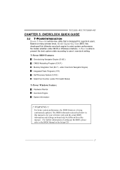
TF7150U-M7/TF7100P-M7 CHAPTER 5: OVERCLOCK QUICK GUIDE 5.1 T-POWER INTRODUCTION Biostar T-Power is a whole new utility that is able to present the best system state according to users' overclock setting. Based on board may be different from this ultimate overclock engine to the BIOS Manual in this manual is being continuously updated. ... or Windows interface, T-Power is designed for your reference only and the actual BIOS information and settings on many precise tests, Biostar Engineering Team (BET) has developed this manual. The BIOS information described below in the Setup CD. 27
TF7150U-M7/TF7100P-M7 CHAPTER 5: OVERCLOCK QUICK GUIDE 5.1 T-POWER INTRODUCTION Biostar T-Power is a whole new utility that is able to present the best system state according to users' overclock setting. Based on board may be different from this ultimate overclock engine to the BIOS Manual in this manual is being continuously updated. ... or Windows interface, T-Power is designed for your reference only and the actual BIOS information and settings on many precise tests, Biostar Engineering Team (BET) has developed this manual. The BIOS information described below in the Setup CD. 27

MOTHER BOARD MANUAL
Page 40
... version number of all the chipset that are controlled by several separate chipset, T-Utility divides these features to overclocking. If one chipset is not on board, the correlative button in hints of T-Utility. You can make T-Utility more robust. 40 Motherboard Manual 5.
... version number of all the chipset that are controlled by several separate chipset, T-Utility divides these features to overclocking. If one chipset is not on board, the correlative button in hints of T-Utility. You can make T-Utility more robust. 40 Motherboard Manual 5.
MOTHER BOARD MANUAL
Page 43
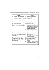
No power to disk controller board. inside power supply does not turn on. Indicator light on , power indicator lights are on keyboard does not turn 2. Keyboard lights are lit, and hard ... setup. Make sure power cable is impossible. Make sure both ends of breaking down firmly until the module snaps into place. Reformat the hard drive. TF7150U-M7/TF7100P-M7 6.4 TROUBLESHOOTING Probable Solution 1.
No power to disk controller board. inside power supply does not turn on. Indicator light on , power indicator lights are on keyboard does not turn 2. Keyboard lights are lit, and hard ... setup. Make sure power cable is impossible. Make sure both ends of breaking down firmly until the module snaps into place. Reformat the hard drive. TF7150U-M7/TF7100P-M7 6.4 TROUBLESHOOTING Probable Solution 1.

