
Setup Manual
Page 1
... and used in accordance with the limits of a Class B digital device, pursuant to Part 15 of the FCC Rules. T41 HD Setup Manual FCC Information and Copyright This equipment has been tested and found in this publication and to make changes to the contents here without...obtaining the vendor's approval in a residential installation. Further the vendor reserves the right to revise this user's manual. These limits are trademarks of this user's manual is subject to provide reasonable protection against harmful interference in writing. All the brand and product names are designed...
... and used in accordance with the limits of a Class B digital device, pursuant to Part 15 of the FCC Rules. T41 HD Setup Manual FCC Information and Copyright This equipment has been tested and found in this publication and to make changes to the contents here without...obtaining the vendor's approval in a residential installation. Further the vendor reserves the right to revise this user's manual. These limits are trademarks of this user's manual is subject to provide reasonable protection against harmful interference in writing. All the brand and product names are designed...
Setup Manual
Page 3
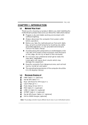
CHAPTER 1: INTRODUCTION T41 HD 1.1 BEFORE YOU START Thank you take the motherboard out from dangerous area, such as heat source, humid air and water. „ The operating temperatures of ... a dry and stable working environment with sufficient lighting. „ Always disconnect the computer from power outlet before operation. „ Before you for ATX Case X 1 User's Manual X 1 Fully Setup Driver CD X 1 FDD Cable X 1 (optional) USB 2.0 Cable X1 (optional) S/PDIF Cable X 1 (optional) Serial ATA Power Cable X 1 (optional) DVI to 45 degrees Celsius. 1.2 PACKAGE...
CHAPTER 1: INTRODUCTION T41 HD 1.1 BEFORE YOU START Thank you take the motherboard out from dangerous area, such as heat source, humid air and water. „ The operating temperatures of ... a dry and stable working environment with sufficient lighting. „ Always disconnect the computer from power outlet before operation. „ Before you for ATX Case X 1 User's Manual X 1 Fully Setup Driver CD X 1 FDD Cable X 1 (optional) USB 2.0 Cable X1 (optional) S/PDIF Cable X 1 (optional) Serial ATA Power Cable X 1 (optional) DVI to 45 degrees Celsius. 1.2 PACKAGE...
Setup Manual
Page 4
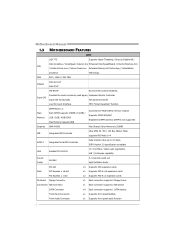
Motherboard Manual 1.3 MOTHERBOARD FEATURES SPEC LGA 775 Supports Hyper-Threading / Execute Disable Bit / Intel Core2Duo / Core2Quad / Celeron 4xx Enhanced Intel SpeedStep® / Intel Architecture-64 / CPU / Pentium ...
Motherboard Manual 1.3 MOTHERBOARD FEATURES SPEC LGA 775 Supports Hyper-Threading / Execute Disable Bit / Intel Core2Duo / Core2Quad / Celeron 4xx Enhanced Intel SpeedStep® / Intel Architecture-64 / CPU / Pentium ...
Setup Manual
Page 6
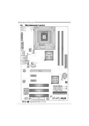
P H4 PH 3 P H2 PH 1 Motherboard Manual 1.5 MOTHERBOARD LAYOUT KBMS1 LGA775 CPU1 V GA 1 DV I1 D DR2_A1 D DR2_B1 USB1 ATXPWR2 CPU_FAN1 JUSBV1 RJ45USB1 CD_ I N1 AUDIO1 SYS_FAN1 Intel G41 A3 SPDIF1 AUXPWR1 LAN PEX16_1 ATXPWR1 CODEC PEX1_1 PEX1_2 Intel ICH7 BAT1 JCMO S1 BI O S PCI1 SATA1 SATA3 SW _RST1 Super PCI2 I/O SATA2 SW _PW R1 SATA4 IDE1 PCI3 JUSBV2 F_AUDIO1 F_COM1 FDD1 SYS_FAN2 F_USB1 F_USB2 LED2 L ED1 PANEL1 Note: ■ represents the 1st pin. 4
P H4 PH 3 P H2 PH 1 Motherboard Manual 1.5 MOTHERBOARD LAYOUT KBMS1 LGA775 CPU1 V GA 1 DV I1 D DR2_A1 D DR2_B1 USB1 ATXPWR2 CPU_FAN1 JUSBV1 RJ45USB1 CD_ I N1 AUDIO1 SYS_FAN1 Intel G41 A3 SPDIF1 AUXPWR1 LAN PEX16_1 ATXPWR1 CODEC PEX1_1 PEX1_2 Intel ICH7 BAT1 JCMO S1 BI O S PCI1 SATA1 SATA3 SW _RST1 Super PCI2 I/O SATA2 SW _PW R1 SATA4 IDE1 PCI3 JUSBV2 F_AUDIO1 F_COM1 FDD1 SYS_FAN2 F_USB1 F_USB2 LED2 L ED1 PANEL1 Note: ■ represents the 1st pin. 4
Setup Manual
Page 8
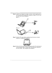
Step 2-1: Step 2-2: Step 3: Hold the CPU down firmly, and then lower the lever to locked position to complete the installation. Connect the CPU FAN power cable into the CPU_FAN1. This completes the installation. 6 Motherboard Manual Step 2: Look for the triangular cut edge on socket, and the golden dot on the retention frame. The CPU will fit only in the correct orientation. Step 4: Put the CPU Fan and heatsink assembly on the CPU and buckle it on CPU should point forwards this triangular cut edge.
Step 2-1: Step 2-2: Step 3: Hold the CPU down firmly, and then lower the lever to locked position to complete the installation. Connect the CPU FAN power cable into the CPU_FAN1. This completes the installation. 6 Motherboard Manual Step 2: Look for the triangular cut edge on socket, and the golden dot on the retention frame. The CPU will fit only in the correct orientation. Step 4: Put the CPU Fan and heatsink assembly on the CPU and buckle it on CPU should point forwards this triangular cut edge.
Setup Manual
Page 10
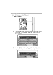
Insert the DIMM vertically and firmly into the slot until the retaining chip snap back in place and the DIMM is properly seated. 8 Memory Modules 1. DDR2_A1 DDR2_B1 Motherboard Manual 2.3 INSTALLING SYSTEM MEMORY A. Align a DIMM on the slot such that the notch on the DIMM matches the break on the Slot. 2. Unlock a DIMM slot by pressing the retaining clips outward.
Insert the DIMM vertically and firmly into the slot until the retaining chip snap back in place and the DIMM is properly seated. 8 Memory Modules 1. DDR2_A1 DDR2_B1 Motherboard Manual 2.3 INSTALLING SYSTEM MEMORY A. Align a DIMM on the slot such that the notch on the DIMM matches the break on the Slot. 2. Unlock a DIMM slot by pressing the retaining clips outward.
Setup Manual
Page 12
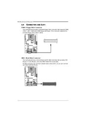
This connector supports the provided floppy drive ribbon cables. 2 34 1 33 IDE1: Hard Disk Connector The motherboard has a 32-bit Enhanced PCI IDE Controller that supports 360K, 720K, 1.2M, 1.44M and 2.88M floppy disk types. Motherboard Manual 2.4 CONNECTORS AND SLOTS FDD1: Floppy Disk Connector The motherboard provides a standard floppy disk connector that provides PIO Mode 0~4, Bus Master, and Ultra DMA 33/66/100 functionality. An IDE connector can connect a master and a slave drive, so you can connect up to two hard disk drives. 2 40 1 39 10
This connector supports the provided floppy drive ribbon cables. 2 34 1 33 IDE1: Hard Disk Connector The motherboard has a 32-bit Enhanced PCI IDE Controller that supports 360K, 720K, 1.2M, 1.44M and 2.88M floppy disk types. Motherboard Manual 2.4 CONNECTORS AND SLOTS FDD1: Floppy Disk Connector The motherboard provides a standard floppy disk connector that provides PIO Mode 0~4, Bus Master, and Ultra DMA 33/66/100 functionality. An IDE connector can connect a master and a slave drive, so you can connect up to two hard disk drives. 2 40 1 39 10
Setup Manual
Page 14
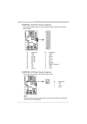
Motherboard Manual ATXPWR1: ATX Power Source Connector This connector allows user to connect 24-pin power connector on the ATX power supply. 12 24 1 13 Pin Assignment ...
Motherboard Manual ATXPWR1: ATX Power Source Connector This connector allows user to connect 24-pin power connector on the ATX power supply. 12 24 1 13 Pin Assignment ...
Setup Manual
Page 16
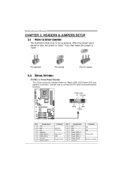
... Panel Header This 16-pin connector includes Power-on, Reset, HDD LED, Power LED, and speaker connection. It allows user to set up jumpers. Motherboard Manual CHAPTER 3: HEADERS & JUMPERS SETUP 3.1 HOW TO SETUP JUMPERS The illustration shows how to connect the PC case's front panel switch functions.
... Panel Header This 16-pin connector includes Power-on, Reset, HDD LED, Power LED, and speaker connection. It allows user to set up jumpers. Motherboard Manual CHAPTER 3: HEADERS & JUMPERS SETUP 3.1 HOW TO SETUP JUMPERS The illustration shows how to connect the PC case's front panel switch functions.
Setup Manual
Page 18
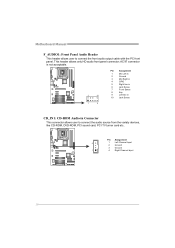
... user to connect the front audio output cable with the PC front panel. Pin Assignment 4 1 Left Channel Input 2 Ground 3 Ground 1 4 Right Channel Input 16 Motherboard Manual F_AUDIO1: Front Panel Audio Header This header allows user to connect the audio source from the variaty devices, like CD-ROM, DVD-ROM, PCI sound...
... user to connect the front audio output cable with the PC front panel. Pin Assignment 4 1 Left Channel Input 2 Ground 3 Ground 1 4 Right Channel Input 16 Motherboard Manual F_AUDIO1: Front Panel Audio Header This header allows user to connect the audio source from the variaty devices, like CD-ROM, DVD-ROM, PCI sound...
Setup Manual
Page 20
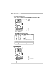
Motherboard Manual On-Board LED Indicators There are 2 on the motherboard showing system status. SW_PWR1: Power Switch button. 18 SW_RST1 SW_PWR1 SW_RST1: Reset button. PH 4 PH 3 PH 2 PH 1 LED2 LED1 LED1 & LED2: Debug Indicators PH1 ~ PH4: Power Status Indicators Please refer to the tables below for specific messages: LED1 LED2 Message ON ON OFF OFF ON Normal OFF Memory Error ON VGA Error OFF Abnormal: CPU / Chipset error. PH1 ~ PH4 ON OFF Phase Indicator Phase Active Phase Inactive On-Board Buttons There are 6 LED indicators on -board buttons.
Motherboard Manual On-Board LED Indicators There are 2 on the motherboard showing system status. SW_PWR1: Power Switch button. 18 SW_RST1 SW_PWR1 SW_RST1: Reset button. PH 4 PH 3 PH 2 PH 1 LED2 LED1 LED1 & LED2: Debug Indicators PH1 ~ PH4: Power Status Indicators Please refer to the tables below for specific messages: LED1 LED2 Message ON ON OFF OFF ON Normal OFF Memory Error ON VGA Error OFF Abnormal: CPU / Chipset error. PH1 ~ PH4 ON OFF Phase Indicator Phase Active Phase Inactive On-Board Buttons There are 6 LED indicators on -board buttons.

Setup Manual
Page 21
...American Megatrends, Inc. 19 A. OverClock Navigator [Normal] =========== Automate OverClock System =========== Auto OverClock System [V6-Tech Engine] Manual OverClock System Intel(R) SpeedStep(tm) tech [Enabled] Ratio CMOS Setting [ x9.0] CPU Frequency Setting [200] PCIE Frequency ... T-SERIES BIOS & SOFTWARE 4.1 T-SERIES BIOS T41 HD T-Series BIOS Features Overclocking Navigator Engine (O.N.E.) Memory Integration Test (M.I.T., under Overclock Navigator Engine) BIO-Flasher: Update BIOS file from this manual is being continuously updated. For better system performance...
...American Megatrends, Inc. 19 A. OverClock Navigator [Normal] =========== Automate OverClock System =========== Auto OverClock System [V6-Tech Engine] Manual OverClock System Intel(R) SpeedStep(tm) tech [Enabled] Ratio CMOS Setting [ x9.0] CPU Frequency Setting [200] PCIE Frequency ... T-SERIES BIOS & SOFTWARE 4.1 T-SERIES BIOS T41 HD T-Series BIOS Features Overclocking Navigator Engine (O.N.E.) Memory Integration Test (M.I.T., under Overclock Navigator Engine) BIO-Flasher: Update BIOS file from this manual is being continuously updated. For better system performance...
Setup Manual
Page 22
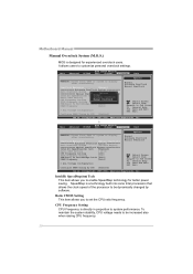
..., Inc. CPU Frequency Setting CPU Frequency is directly in proportion to be dynamically changed by SPD [Enabled] Normal Automate OverClock Manual OverClock Select Screen Select Item EnterGo to set the CPU ratio frequency. To maintain the system stability, CPU voltage needs to system performance.... Motherboard Manual Manual Overclock System (M.O.S.) MOS is a technology built into some Intel processors that allows the clock speed of the processor to be ...
..., Inc. CPU Frequency Setting CPU Frequency is directly in proportion to be dynamically changed by SPD [Enabled] Normal Automate OverClock Manual OverClock Select Screen Select Item EnterGo to set the CPU ratio frequency. To maintain the system stability, CPU voltage needs to system performance.... Motherboard Manual Manual Overclock System (M.O.S.) MOS is a technology built into some Intel processors that allows the clock speed of the processor to be ...

Setup Manual
Page 23
... inexperienced users. We also would not guarantee any hardware damage which may be caused by SPD [Enabled] Options Normal Automate OverClock Manual OverClock Select Screen Select Item EnterGo to select the FSB Frequency. T41 HD PCIE Clock By It helps increase VGA card performance. Configure DRAM Timing by SPD Adjust the DRAM timing...
... inexperienced users. We also would not guarantee any hardware damage which may be caused by SPD [Enabled] Options Normal Automate OverClock Manual OverClock Select Screen Select Item EnterGo to select the FSB Frequency. T41 HD PCIE Clock By It helps increase VGA card performance. Configure DRAM Timing by SPD Adjust the DRAM timing...
Setup Manual
Page 24
...American Megatrends, Inc. OverClock Navigator [Automate OverClock] =========== Automate OverClock System =========== Auto OverClock System [V8-Tech Engine] Manual OverClock System Intel(R) SpeedStep(tm) tech [Enabled] Ratio CMOS Setting [ x9.0] CPU Frequency Setting [200] PCIE ... over -clock performance. OverClock Navigator [Automate OverClock] =========== Automate OverClock System =========== Auto OverClock System [V12-Tech Engine] Manual OverClock System Intel(R) SpeedStep(tm) tech [Enabled] Ratio CMOS Setting [ x9.0] CPU Frequency Setting [200] PCIE Frequency...
...American Megatrends, Inc. OverClock Navigator [Automate OverClock] =========== Automate OverClock System =========== Auto OverClock System [V8-Tech Engine] Manual OverClock System Intel(R) SpeedStep(tm) tech [Enabled] Ratio CMOS Setting [ x9.0] CPU Frequency Setting [200] PCIE ... over -clock performance. OverClock Navigator [Automate OverClock] =========== Automate OverClock System =========== Auto OverClock System [V12-Tech Engine] Manual OverClock System Intel(R) SpeedStep(tm) tech [Enabled] Ratio CMOS Setting [ x9.0] CPU Frequency Setting [200] PCIE Frequency...

Setup Manual
Page 25
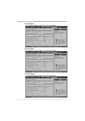
...the system to complete the test. 23 Options OverClock Navigator [Normal] =========== Automate OverClock System =========== Auto OverClock System [V6-Tech Engine] Manual OverClock System Intel(R) SpeedStep(tm) tech Ratio CMOS Setting [Enabled] [ x9.0] CPU Frequency Setting PCIE Frequency Setting [200] [100]..., and no extra devices or software are needed. the condition parameter should be based on the selected CPU model. T41 HD Notices: Not all types of Intel CPU perform above overclock setting ideally; Memory Integration Test (M.I.T.) This function is "Disabled...
...the system to complete the test. 23 Options OverClock Navigator [Normal] =========== Automate OverClock System =========== Auto OverClock System [V6-Tech Engine] Manual OverClock System Intel(R) SpeedStep(tm) tech Ratio CMOS Setting [Enabled] [ x9.0] CPU Frequency Setting PCIE Frequency Setting [200] [100]..., and no extra devices or software are needed. the condition parameter should be based on the selected CPU model. T41 HD Notices: Not all types of Intel CPU perform above overclock setting ideally; Memory Integration Test (M.I.T.) This function is "Disabled...
Setup Manual
Page 26
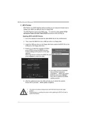
... computer and then press during the Power-On Self Tests (POST) procedure while booting up. z This utility only allows storage device with BIO-Flasher 1. Motherboard Manual C. BIO-Flasher BIO-Flasher is built in the BIOS chip. Then, save the BIOS file into a USB pen drive or a floppy disk. 3. Insert the USB...
... computer and then press during the Power-On Self Tests (POST) procedure while booting up. z This utility only allows storage device with BIO-Flasher 1. Motherboard Manual C. BIO-Flasher BIO-Flasher is built in the BIOS chip. Then, save the BIOS file into a USB pen drive or a floppy disk. 3. Insert the USB...
Setup Manual
Page 28
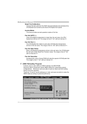
... 1. Control Mode This item provides several operation modes of CPU/System fan. Fan Ctrl Sensitive Increasing the value of slope PWM will turn off. Motherboard Manual Smart Fan Calibration Choose this set value.
... 1. Control Mode This item provides several operation modes of CPU/System fan. Fan Ctrl Sensitive Increasing the value of slope PWM will turn off. Motherboard Manual Smart Fan Calibration Choose this set value.
Setup Manual
Page 30
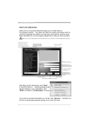
.... Before you use this information, click "Send" to help you fix the problem. A warning dialog would be able to cancel. Send th e mail ou t. Motherboard Manual eHot-Line (Optional) eHot-Line is useful for your default e-mail clientapplication program. * represent s import ant information that you must provide.
.... Before you use this information, click "Send" to help you fix the problem. A warning dialog would be able to cancel. Send th e mail ou t. Motherboard Manual eHot-Line (Optional) eHot-Line is useful for your default e-mail clientapplication program. * represent s import ant information that you must provide.

Setup Manual
Page 32
... to complete the BIOS Backup procedure. 30 Click on this button, the saving dialog will show . After the saving process, finish dialog will show . Motherboard Manual BIOS Update BIOS Update is a convenient utility which allows you to a .bin file Update BIOS with a BIOS file Once click on OK to save file...
... to complete the BIOS Backup procedure. 30 Click on this button, the saving dialog will show . After the saving process, finish dialog will show . Motherboard Manual BIOS Update BIOS Update is a convenient utility which allows you to a .bin file Update BIOS with a BIOS file Once click on OK to save file...

