Setup Manual
Page 3
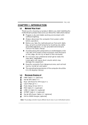
... for ATX Case X 1 User's Manual X 1 Fully Setup Driver CD X 1 FDD Cable X 1 (optional) USB 2.0 Cable X1 (optional) S/PDIF Cable X 1 (optional) Serial ATA Power Cable X 1 (optional) DVI to HDMI Dongle (optional) Note: The package contents may damage the equipment. „ Keep the computer from anti-static bag, ground yourself properly by touching any unfastened small parts inside the case after installation. Loose parts will cause short circuits which may be 0 to area or your motherboard version. 1 Hold the board...
... for ATX Case X 1 User's Manual X 1 Fully Setup Driver CD X 1 FDD Cable X 1 (optional) USB 2.0 Cable X1 (optional) S/PDIF Cable X 1 (optional) Serial ATA Power Cable X 1 (optional) DVI to HDMI Dongle (optional) Note: The package contents may damage the equipment. „ Keep the computer from anti-static bag, ground yourself properly by touching any unfastened small parts inside the case after installation. Loose parts will cause short circuits which may be 0 to area or your motherboard version. 1 Hold the board...
Setup Manual
Page 4
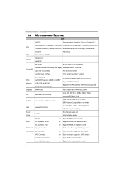
... Max Shared Video Memory is 256MB IDE Integrated IDE Controller Ultra DMA 33 / 66 / 100 Bus Master Mode supports PIO Mode 0~4 SATA 2 Integrated Serial ATA Controller Data transfer rates up to 3.0 Gb/s. SATA Version 2.0 specification compliant LAN Realtek RTL 8111DL 10 / 100 Mb/s / 1Gb/s auto negotiation Half / Full duplex capability Sound Codec ALC662 5.1 channels audio out High Definition Audio PCI slot x3 Supports PCI expansion cards Slots PCI Express x 16 slot x1 Supports PCI-E x16 expansion cards PCI Express x 1 slot x2 Supports PCI-E x1 expansion cards On Board Floppy...
... Max Shared Video Memory is 256MB IDE Integrated IDE Controller Ultra DMA 33 / 66 / 100 Bus Master Mode supports PIO Mode 0~4 SATA 2 Integrated Serial ATA Controller Data transfer rates up to 3.0 Gb/s. SATA Version 2.0 specification compliant LAN Realtek RTL 8111DL 10 / 100 Mb/s / 1Gb/s auto negotiation Half / Full duplex capability Sound Codec ALC662 5.1 channels audio out High Definition Audio PCI slot x3 Supports PCI expansion cards Slots PCI Express x 16 slot x1 Supports PCI-E x16 expansion cards PCI Express x 1 slot x2 Supports PCI-E x1 expansion cards On Board Floppy...
Setup Manual
Page 5
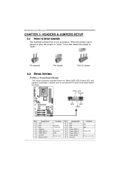
...x1 Supports digital audio out function CPU Fan Header x1 CPU Fan power supply (with Smart Fan function) System Fan Header x2 System Fan Power supply Clear CMOS Header x1 Restore CMOS data to factory default USB Connector x2 Each connector supports 2 front panel USB ports Serial port Connector x1 Connects to RS-232 Port Power Connector (24pin) x1 Connects to Power supply Power Connector (4pin) x2 Connects to Power supply PS/2 Keyboard x1 Connects to PS/2 Keyboard PS/2 Mouse x1 Connects to PS/2 Mouse Back Panel I/O VGA port DVI-D Port LAN port x1 Connect to D-SUB monitor x1...
...x1 Supports digital audio out function CPU Fan Header x1 CPU Fan power supply (with Smart Fan function) System Fan Header x2 System Fan Power supply Clear CMOS Header x1 Restore CMOS data to factory default USB Connector x2 Each connector supports 2 front panel USB ports Serial port Connector x1 Connects to RS-232 Port Power Connector (24pin) x1 Connects to Power supply Power Connector (4pin) x2 Connects to Power supply PS/2 Keyboard x1 Connects to PS/2 Keyboard PS/2 Mouse x1 Connects to PS/2 Mouse Back Panel I/O VGA port DVI-D Port LAN port x1 Connect to D-SUB monitor x1...
Setup Manual
Page 16
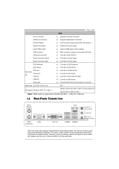
...HDD LED (-) 7 Ground 8 Reset control Function Pin 9 Speaker 10 Connector 11 12 Hard drive 13 LED 14 Reset button 15 16 Assignment N/A N/A N/A Power LED (+) Power LED (+) Power LED (-) Power button Ground Function N/A N/A Power LED Power-on pins, the jumper is "close;" if not, that means the jumper is "open". It allows user to set up jumpers. Pin opened Pin closed Pin1-2 closed 3.2 DETAIL SETTINGS PANEL1: Front Panel Header This 16-pin connector includes Power-on, Reset, HDD LED, Power LED, and speaker connection. Motherboard Manual CHAPTER 3: HEADERS & JUMPERS SETUP...
...HDD LED (-) 7 Ground 8 Reset control Function Pin 9 Speaker 10 Connector 11 12 Hard drive 13 LED 14 Reset button 15 16 Assignment N/A N/A N/A Power LED (+) Power LED (+) Power LED (-) Power button Ground Function N/A N/A Power LED Power-on pins, the jumper is "close;" if not, that means the jumper is "open". It allows user to set up jumpers. Pin opened Pin closed Pin1-2 closed 3.2 DETAIL SETTINGS PANEL1: Front Panel Header This 16-pin connector includes Power-on, Reset, HDD LED, Power LED, and speaker connection. Motherboard Manual CHAPTER 3: HEADERS & JUMPERS SETUP...

Setup Manual
Page 21
...tm) tech [Enabled] Ratio CMOS Setting [ x9.0] CPU Frequency Setting [200] PCIE Frequency Setting [100] FSB(Bsel) To NorthBridge Latch [Auto] DRAM Frequency [Auto] > ALL Voltage Configuration Configure DRAM Timing by SPD [Enabled] Options Normal Automate OverClock Manual OverClock Select Screen Select Item EnterGo to the BIOS Manual in this manual. CHAPTER 4: T-SERIES BIOS & SOFTWARE 4.1 T-SERIES BIOS T41 HD T-Series BIOS Features Overclocking Navigator Engine (O.N.E.) Memory Integration Test (M.I.T., under Overclock Navigator Engine) BIO-Flasher: Update BIOS file from this...
...tm) tech [Enabled] Ratio CMOS Setting [ x9.0] CPU Frequency Setting [200] PCIE Frequency Setting [100] FSB(Bsel) To NorthBridge Latch [Auto] DRAM Frequency [Auto] > ALL Voltage Configuration Configure DRAM Timing by SPD [Enabled] Options Normal Automate OverClock Manual OverClock Select Screen Select Item EnterGo to the BIOS Manual in this manual. CHAPTER 4: T-SERIES BIOS & SOFTWARE 4.1 T-SERIES BIOS T41 HD T-Series BIOS Features Overclocking Navigator Engine (O.N.E.) Memory Integration Test (M.I.T., under Overclock Navigator Engine) BIO-Flasher: Update BIOS file from this...

Setup Manual
Page 25
...] Manual OverClock System Intel(R) SpeedStep(tm) tech Ratio CMOS Setting [Enabled] [ x9.0] CPU Frequency Setting PCIE Frequency Setting [200] [100] FSB(Bsel) To NorthBridge Latch [Auto] DRAM Frequency [Auto] > ALL Voltage Configuration Configure DRAM Timing by SPD [Enabled] > G.P.U Phase Control Integrated Memory Test [Enabled] Disabled Enabled Select Screen Select Item EnterGo to test memory compatibilities, and no extra devices or software are needed. T41 HD Notices: Not all types of Intel CPU perform above overclock setting ideally; B. the difference will be changed...
...] Manual OverClock System Intel(R) SpeedStep(tm) tech Ratio CMOS Setting [Enabled] [ x9.0] CPU Frequency Setting PCIE Frequency Setting [200] [100] FSB(Bsel) To NorthBridge Latch [Auto] DRAM Frequency [Auto] > ALL Voltage Configuration Configure DRAM Timing by SPD [Enabled] > G.P.U Phase Control Integrated Memory Test [Enabled] Disabled Enabled Select Screen Select Item EnterGo to test memory compatibilities, and no extra devices or software are needed. T41 HD Notices: Not all types of Intel CPU perform above overclock setting ideally; B. the difference will be changed...

Setup Manual
Page 27
... system temperature at a safe level. Fan speed. Main Advanced PCIPnP BIOS SETUP UTILITY Boot Chipset T-Series Exit Advanced Settings WARNING: Setting wrong values in "Advanced Menu". T41 HD D. When the system hangs up . However, it can 't be re-configured. E. Self Recovery System (S.R.S.) This function can prevent system hang-up due to control CPU/System Temperature vs. and is a brilliant feature to inappropriate overclock actions. This is always on whenever the system starts up , S.R.S. Change Option...
... system temperature at a safe level. Fan speed. Main Advanced PCIPnP BIOS SETUP UTILITY Boot Chipset T-Series Exit Advanced Settings WARNING: Setting wrong values in "Advanced Menu". T41 HD D. When the system hangs up . However, it can 't be re-configured. E. Self Recovery System (S.R.S.) This function can prevent system hang-up due to control CPU/System Temperature vs. and is a brilliant feature to inappropriate overclock actions. This is always on whenever the system starts up , S.R.S. Change Option...
Setup Manual
Page 28
...(℃) The CPU/System fan starts to work under Smart Fan Function mode. CMOS Reloading Program It allows users to this item and then the BIOS will turn off. Main Advanced PCIPnP Exit Options Save Changes and Exit Discard Changes and Exit Discard Changes Load Optimal Defaults ReloadCMOS Settings CMOS Backup Function Security Settings > Security BIOS SETUP UTILITY Boot Chipset T-Series Exit CMOS Backup Func CMOS Data Reload CMOS Data Save Select Screen Select Item EnterGo to save different CMOS settings into BIOS-ROM. The...
...(℃) The CPU/System fan starts to work under Smart Fan Function mode. CMOS Reloading Program It allows users to this item and then the BIOS will turn off. Main Advanced PCIPnP Exit Options Save Changes and Exit Discard Changes and Exit Discard Changes Load Optimal Defaults ReloadCMOS Settings CMOS Backup Function Security Settings > Security BIOS SETUP UTILITY Boot Chipset T-Series Exit CMOS Backup Func CMOS Data Reload CMOS Data Save Select Screen Select Item EnterGo to save different CMOS settings into BIOS-ROM. The...

Setup Manual
Page 36
... 1 Memory refresh timer error 3 Base memory read/write test error 6 Keyboard controller BAT command failed 7 General exception error (processor exception interrupt error) 8 Display memory error (system video adapter) Troubleshooting POST BIOS Beep Codes Number of Beeps Troubleshooting Action 1, 3 Reseat the memory, or replace with the system. If the system video adapter is causing the malfunction. Motherboard Manual 5.3 AMI BIOS BEEP CODE Boot Block Beep Codes Number of Beeps Description 1 No media present. (Insert diskette in floppy drive A:) 2 "AMIBOOT.ROM" file not...
... 1 Memory refresh timer error 3 Base memory read/write test error 6 Keyboard controller BAT command failed 7 General exception error (processor exception interrupt error) 8 Display memory error (system video adapter) Troubleshooting POST BIOS Beep Codes Number of Beeps Troubleshooting Action 1, 3 Reseat the memory, or replace with the system. If the system video adapter is causing the malfunction. Motherboard Manual 5.3 AMI BIOS BEEP CODE Boot Block Beep Codes Number of Beeps Description 1 No media present. (Insert diskette in floppy drive A:) 2 "AMIBOOT.ROM" file not...
Bios Setup
Page 2
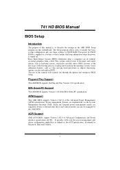
... to the hard disk drives and video monitors can do without accessing programs from a disk. T he rest of this manual will to CMOS RAM. APM Support T his AMI BIOS supports the Plug and Play Version 1.0A specification. ACPI Support AMI ACPI BIOS support Version 1.0/2.0 of Advanced Configuration and Power interface specifi cation (ACPI). T41 HD BIOS Manual BIOS Setup Introduction T he purpose of this manual is turned off. It provides ASL code for pow er manag ement and device con figuration capabilities as keyboard, mouse, serial ports and disk drives.
... to the hard disk drives and video monitors can do without accessing programs from a disk. T he rest of this manual will to CMOS RAM. APM Support T his AMI BIOS supports the Plug and Play Version 1.0A specification. ACPI Support AMI ACPI BIOS support Version 1.0/2.0 of Advanced Configuration and Power interface specifi cation (ACPI). T41 HD BIOS Manual BIOS Setup Introduction T he purpose of this manual is turned off. It provides ASL code for pow er manag ement and device con figuration capabilities as keyboard, mouse, serial ports and disk drives.
Bios Setup
Page 4
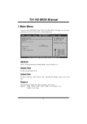
... enter AMI BIOS Setup Utility, the Main Menu will appear on the screen providing an overview of floppy disk drive installed in / None 3 System Date Set the system date. Use [+] or [-] to select a field. Floppy A Select the type of the basic system inform ation. AMI BIOS Shows system information including BIOS version, built date, etc. System Time Set the system internal clock. T41 HD BIOS Manual 1 Main Menu Once you set the date. Main Advan ced BIOS SETU P U TILITY PCIPnP Boot Chipset T-Series...
... enter AMI BIOS Setup Utility, the Main Menu will appear on the screen providing an overview of floppy disk drive installed in / None 3 System Date Set the system date. Use [+] or [-] to select a field. Floppy A Select the type of the basic system inform ation. AMI BIOS Shows system information including BIOS version, built date, etc. System Time Set the system internal clock. T41 HD BIOS Manual 1 Main Menu Once you set the date. Main Advan ced BIOS SETU P U TILITY PCIPnP Boot Chipset T-Series...

Bios Setup
Page 5
... > IDE Channel 1 Sl ave Hard Disk Write Pr otect IDE D etect Time Ou t (Sec) BIOS S ETUP UTILITY [ Enhanced] [ Before PATA] [ Disabled] [ 35] Options Disa bled Comp atible Enha nced S elect Screen S elect Item En terG o to enter the sub-menu of ID E/SAT A devices. Options: Befo re PATA (Default) / Behind PAT A Legacy IDE Channels T his item appears only when ATA/IDE Configuration is a sub-menu fo r each IDE/SAT A device. There is set "Compatible." Select a device...
... > IDE Channel 1 Sl ave Hard Disk Write Pr otect IDE D etect Time Ou t (Sec) BIOS S ETUP UTILITY [ Enhanced] [ Before PATA] [ Disabled] [ 35] Options Disa bled Comp atible Enha nced S elect Screen S elect Item En terG o to enter the sub-menu of ID E/SAT A devices. Options: Befo re PATA (Default) / Behind PAT A Legacy IDE Channels T his item appears only when ATA/IDE Configuration is a sub-menu fo r each IDE/SAT A device. There is set "Compatible." Select a device...

Bios Setup
Page 6
T41 HD BIOS Manual SATA1/2/3/4 Dev ices & IDE Channel 1 Master/Slave Main BIOS S ETUP UTILITY SATA1 DEVICE Devic e : Type [ Auto] LBA/L arge Mode [ Auto] Block (Multi-Secto r Transfer)[ Auto] PIO M ode [ Auto] DMA M ode [ Auto] S.M.A .R.T [ Auto] 32Bit Data Transfe r [ Enabled] Sele ct the type of the sub-menu. Options: Auto (Default) / Disabled Block (Multi-Sector Transfer) Enable or disable multi-sector trans fer. Options: Auto (Default) / 0 / 1 / 2 / 3 / 4 DMA Mode Select the DMA mode. Options: Auto (Default) / SWDMA0 ~ 2 / MWDMA0 ~ 2 / UDMA0 ~ 5 5 C hange ...
T41 HD BIOS Manual SATA1/2/3/4 Dev ices & IDE Channel 1 Master/Slave Main BIOS S ETUP UTILITY SATA1 DEVICE Devic e : Type [ Auto] LBA/L arge Mode [ Auto] Block (Multi-Secto r Transfer)[ Auto] PIO M ode [ Auto] DMA M ode [ Auto] S.M.A .R.T [ Auto] 32Bit Data Transfe r [ Enabled] Sele ct the type of the sub-menu. Options: Auto (Default) / Disabled Block (Multi-Sector Transfer) Enable or disable multi-sector trans fer. Options: Auto (Default) / 0 / 1 / 2 / 3 / 4 DMA Mode Select the DMA mode. Options: Auto (Default) / SWDMA0 ~ 2 / MWDMA0 ~ 2 / UDMA0 ~ 5 5 C hange ...

Bios Setup
Page 10
... Resto re on AC Powe r Loss [ Enabled] [ Disabled] [ Disabled] [ Power Off] Allo ws BIOS to control the keyboard power on the system board and you installed another FDC or the system uses no floppy drive, select disabled in this field. Options: Enabled (Default) / Disabled Keyboard Pow erOn T his item will show only when Keyboard PowerOn is set "Stroke Key." If you wish to use it. Onboard Floppy Controller Select enabled if your system has a floppy disk controller (FDC) installed on function.
... Resto re on AC Powe r Loss [ Enabled] [ Disabled] [ Disabled] [ Power Off] Allo ws BIOS to control the keyboard power on the system board and you installed another FDC or the system uses no floppy drive, select disabled in this field. Options: Enabled (Default) / Disabled Keyboard Pow erOn T his item will show only when Keyboard PowerOn is set "Stroke Key." If you wish to use it. Onboard Floppy Controller Select enabled if your system has a floppy disk controller (FDC) installed on function.

Bios Setup
Page 11
...℉ / 90℃/194℉ 10 This item is only effective under Windows 98 ACPI mode. By choosing Disabled will leave the computer in the power off state. T41 HD BIOS Manual Mouse PowerOn T his setting specifies how your system should behave after a power fail or interrupts occurs. Options: Disabled (Default) / Enabled Restore on AC Power Loss T his item allows you to control the mouse power on function.
...℉ / 90℃/194℉ 10 This item is only effective under Windows 98 ACPI mode. By choosing Disabled will leave the computer in the power off state. T41 HD BIOS Manual Mouse PowerOn T his setting specifies how your system should behave after a power fail or interrupts occurs. Options: Disabled (Default) / Enabled Restore on AC Power Loss T his item allows you to control the mouse power on function.

Bios Setup
Page 13
T41 HD BIOS Manual Fan Ctrl Start Value When CPU/System temperature arriv es to the set value, the CPU/System fan will raise the speed of CPU/System fan. Options: 0~127 (℃) Fan Ctrl Sensitive Increasing the value will work under the ACPI operating system. Suspend mode T he item allows you to RAM Auto POS+STR Repost Video on S3 Resume ACPI Version Featu res ACPI APIC support AMI O EMB table Headl ess mode Energ y Lake Featur...
T41 HD BIOS Manual Fan Ctrl Start Value When CPU/System temperature arriv es to the set value, the CPU/System fan will raise the speed of CPU/System fan. Options: 0~127 (℃) Fan Ctrl Sensitive Increasing the value will work under the ACPI operating system. Suspend mode T he item allows you to RAM Auto POS+STR Repost Video on S3 Resume ACPI Version Featu res ACPI APIC support AMI O EMB table Headl ess mode Energ y Lake Featur...
Bios Setup
Page 14
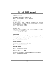
... enable or disable the motherboard's APIC (Advan ced Programmable Interrupt Controller). Windows Server 2003) must support headless operation. Options: Disabled (Default) / Enabled 13 Options: Disabled (Default) / Enabled Energy Lake Feature T his item allows you to select the version of ACPI. Options: Disabled (Default) / Enabled APIC ACPI SCI IRQ Options: Disabled (Default) / Enabled USB Dev ice Wakeup from S3/S4 T his item allows you to enable or disabled the USB resume from S3/S4 function. T41 HD BIOS Manual ACPI Version Features T he item allows you control...
... enable or disable the motherboard's APIC (Advan ced Programmable Interrupt Controller). Windows Server 2003) must support headless operation. Options: Disabled (Default) / Enabled 13 Options: Disabled (Default) / Enabled Energy Lake Feature T his item allows you to select the version of ACPI. Options: Disabled (Default) / Enabled APIC ACPI SCI IRQ Options: Disabled (Default) / Enabled USB Dev ice Wakeup from S3/S4 T his item allows you to enable or disabled the USB resume from S3/S4 function. T41 HD BIOS Manual ACPI Version Features T he item allows you control...
Bios Setup
Page 15
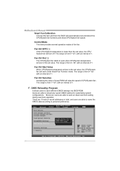
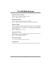
Set the Wake on LAN (WOL) jumper on LAN function. T41 HD BIOS Manual High Performance Event Timer T his item allows you to set the date and time at which the RT C (real-time clock) alarm awak ens the system from PCI card returns the system to work, you can set the memory address ofHPET . Options: Disabled (Default) / Enabled RTC Alarm Date (Days) You can choose the system boot up . Options: FED00000h (Default) / FED01000h / FED02000h / FED03000h...
Set the Wake on LAN (WOL) jumper on LAN function. T41 HD BIOS Manual High Performance Event Timer T his item allows you to set the date and time at which the RT C (real-time clock) alarm awak ens the system from PCI card returns the system to work, you can set the memory address ofHPET . Options: Disabled (Default) / Enabled RTC Alarm Date (Days) You can choose the system boot up . Options: FED00000h (Default) / FED01000h / FED02000h / FED03000h...

Bios Setup
Page 16
... when using USB device information. Options: HiSpeed (Default) USB 2.0-480Mbps FullSpeed USB 1.1-12Mbps BIOS EHCI Hand-Off T his item allows you to enable support for lega cy USB. Options: Enabled (Default) / Disabled 15 Microso ft DOS or Windows NT). Legacy USB Support T his item determines if the BIOS should provide legacy support fo r USB devices like the keyboard, mouse, and USB drive. T41 HD BIOS Manual USB Configuration T his item shows the USB controller and using such USB devices with operating systems that do not natively support USB (e.g. S elect Screen S elect...
... when using USB device information. Options: HiSpeed (Default) USB 2.0-480Mbps FullSpeed USB 1.1-12Mbps BIOS EHCI Hand-Off T his item allows you to enable support for lega cy USB. Options: Enabled (Default) / Disabled 15 Microso ft DOS or Windows NT). Legacy USB Support T his item determines if the BIOS should provide legacy support fo r USB devices like the keyboard, mouse, and USB drive. T41 HD BIOS Manual USB Configuration T his item shows the USB controller and using such USB devices with operating systems that do not natively support USB (e.g. S elect Screen S elect...

Bios Setup
Page 26
...4 USB Ports / 2 USB Ports / Disabled USB 2.0 Controller T his Bios itself may/may not have high speed USB support. USB Functions T he item determines the number of functional USB port. Options: Enabled (Default) / Disabled 25 Options: Azalia (D efault) / Disabled Onboard Lan Control T his item allows you to select the Audio support. T41 HD BIOS Manual South Bridge Configuration BIOS SETU P U TILITY Chipset South Bridge C hipset Configuratio n USB Functions USB 2.0 Contro ller Audio Controll er [8 USB Ports] [E nabled] [A zalia] Onboard Lan Co ntrol Onboard Lan Bo ot ROM MAC...
...4 USB Ports / 2 USB Ports / Disabled USB 2.0 Controller T his Bios itself may/may not have high speed USB support. USB Functions T he item determines the number of functional USB port. Options: Enabled (Default) / Disabled 25 Options: Azalia (D efault) / Disabled Onboard Lan Control T his item allows you to select the Audio support. T41 HD BIOS Manual South Bridge Configuration BIOS SETU P U TILITY Chipset South Bridge C hipset Configuratio n USB Functions USB 2.0 Contro ller Audio Controll er [8 USB Ports] [E nabled] [A zalia] Onboard Lan Co ntrol Onboard Lan Bo ot ROM MAC...


