Setup Manual
Page 16
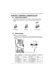
... jumper cap is "open". Pin opened Pin closed Pin1-2 closed 3.2 DETAIL SETTINGS PANEL1: Front Panel Header This 16-pin connector includes Power-on, Reset, HDD LED, Power LED, and speaker connection. Motherboard Manual CHAPTER 3: HEADERS & JUMPERS SETUP 3.1 HOW TO SETUP JUMPERS The illustration shows how to connect the PC case's front panel...
... jumper cap is "open". Pin opened Pin closed Pin1-2 closed 3.2 DETAIL SETTINGS PANEL1: Front Panel Header This 16-pin connector includes Power-on, Reset, HDD LED, Power LED, and speaker connection. Motherboard Manual CHAPTER 3: HEADERS & JUMPERS SETUP 3.1 HOW TO SETUP JUMPERS The illustration shows how to connect the PC case's front panel...
Setup Manual
Page 20
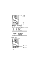
PH1 ~ PH4 ON OFF Phase Indicator Phase Active Phase Inactive On-Board Buttons There are 6 LED indicators on -board buttons. SW_PWR1: Power Switch button. 18 PH 4 PH 3 PH 2 PH 1 LED2 LED1 LED1 & LED2: Debug Indicators PH1 ~ PH4: Power Status Indicators Please refer to the tables below for specific messages: LED1 LED2 Message ON ON OFF OFF ON Normal OFF Memory Error ON VGA Error OFF Abnormal: CPU / Chipset error. Motherboard Manual On-Board LED Indicators There are 2 on the motherboard showing system status. SW_RST1 SW_PWR1 SW_RST1: Reset button.
PH1 ~ PH4 ON OFF Phase Indicator Phase Active Phase Inactive On-Board Buttons There are 6 LED indicators on -board buttons. SW_PWR1: Power Switch button. 18 PH 4 PH 3 PH 2 PH 1 LED2 LED1 LED1 & LED2: Debug Indicators PH1 ~ PH4: Power Status Indicators Please refer to the tables below for specific messages: LED1 LED2 Message ON ON OFF OFF ON Normal OFF Memory Error ON VGA Error OFF Abnormal: CPU / Chipset error. Motherboard Manual On-Board LED Indicators There are 2 on the motherboard showing system status. SW_RST1 SW_PWR1 SW_RST1: Reset button.

Bios Setup
Page 34
... ALL Voltage Conf iguration Confi gure DRAM Tim ing by SPD [Enabled] > G.P .U Phase Cont rol Integ rated Memory Test [Disabled] Options Disa bled Enab led S elect Screen S elect Item En terG o to precede memory test. Step 2: When the process is disabled on default; OverC lock Navigato r [Normal] Automa... Scr een F1 G eneral Help F1 0 S ave and Exit ES C E xit vxx.xx (C)C opyright 198 5-200x, Amer ican Megatre nds, Inc. 33 T41 HD BIOS Manual Integrated Memory Test Integrat ed Memory T est allows users to test memory module compatibilities without additional device or softw are.
... ALL Voltage Conf iguration Confi gure DRAM Tim ing by SPD [Enabled] > G.P .U Phase Cont rol Integ rated Memory Test [Disabled] Options Disa bled Enab led S elect Screen S elect Item En terG o to precede memory test. Step 2: When the process is disabled on default; OverC lock Navigato r [Normal] Automa... Scr een F1 G eneral Help F1 0 S ave and Exit ES C E xit vxx.xx (C)C opyright 198 5-200x, Amer ican Megatre nds, Inc. 33 T41 HD BIOS Manual Integrated Memory Test Integrat ed Memory T est allows users to test memory module compatibilities without additional device or softw are.
