
Setup Manual
Page 1
... responsible for any mistakes found to comply with the limits of a Class B digital device, pursuant to Part 15 of this user's manual is not allowed without first obtaining the vendor's approval in writing. All the brand and product names are designed to provide reasonable protection ...not installed and used in accordance with respect to the contents here and specially disclaims any implied warranties of their respective companies. P31-A7 Setup Manual FCC Information and Copyright This equipment has been tested and found in this publication and to make changes to the contents here ...
... responsible for any mistakes found to comply with the limits of a Class B digital device, pursuant to Part 15 of this user's manual is not allowed without first obtaining the vendor's approval in writing. All the brand and product names are designed to provide reasonable protection ...not installed and used in accordance with respect to the contents here and specially disclaims any implied warranties of their respective companies. P31-A7 Setup Manual FCC Information and Copyright This equipment has been tested and found in this publication and to make changes to the contents here ...

Setup Manual
Page 3
... source, humid air and water. 1.2 PACKAGE CHECKLIST HDD Cable X 1 Serial ATA Cable X 1 Rear I/O Panel for choosing our product. P31-A7 CHAPTER 1: INTRODUCTION 1.1 BEFORE YOU START Thank you take the motherboard out from anti-static bag, ground yourself properly by area or your motherboard ...and stable working environment with sufficient lighting. „ Always disconnect the computer from power outlet before operation. „ Before you for ATX Case X 1 User's Manual X 1 Fully Setup Driver CD X 1 FDD Cable X 1 (optional) USB 2.0 Cable X1 (optional) S/PDIF Cable X 1 (optional) Note: The ...
... source, humid air and water. 1.2 PACKAGE CHECKLIST HDD Cable X 1 Serial ATA Cable X 1 Rear I/O Panel for choosing our product. P31-A7 CHAPTER 1: INTRODUCTION 1.1 BEFORE YOU START Thank you take the motherboard out from anti-static bag, ground yourself properly by area or your motherboard ...and stable working environment with sufficient lighting. „ Always disconnect the computer from power outlet before operation. „ Before you for ATX Case X 1 User's Manual X 1 Fully Setup Driver CD X 1 FDD Cable X 1 (optional) USB 2.0 Cable X1 (optional) S/PDIF Cable X 1 (optional) Note: The ...

Setup Manual
Page 4
... 100 Bus Master Mode supports PIO Mode 0~4 SATA 2 Integrated Serial ATA Controller Data transfer rates up to 3.0 Gb/s. Motherboard Manual 1.3 MOTHERBOARD FEATURES SPEC LGA 775 Supports Hyper-Threading / Execute Disable Bit / Intel Core2Duo / Core2Quad / Celeron 4xx Enhanced Intel... / Celeron D Extended Memory 64 Technology / Virtualization processor Technology FSB Support 533 / 800 / 1066 / 1333 MHz Chipset Intel P31 Intel ICH7 ITE 8712F Environment Control initiatives, Provides the most commonly used legacy Hardware Monitor Controller Super I/O Super I/O functionality. Fan ...
... 100 Bus Master Mode supports PIO Mode 0~4 SATA 2 Integrated Serial ATA Controller Data transfer rates up to 3.0 Gb/s. Motherboard Manual 1.3 MOTHERBOARD FEATURES SPEC LGA 775 Supports Hyper-Threading / Execute Disable Bit / Intel Core2Duo / Core2Quad / Celeron 4xx Enhanced Intel... / Celeron D Extended Memory 64 Technology / Virtualization processor Technology FSB Support 533 / 800 / 1066 / 1333 MHz Chipset Intel P31 Intel ICH7 ITE 8712F Environment Control initiatives, Provides the most commonly used legacy Hardware Monitor Controller Super I/O Super I/O functionality. Fan ...

Setup Manual
Page 6
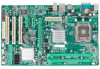
Motherboard Manual 1.5 MOTHERBOARD LAYOUT JKBMS1 LGA775 JCFAN1 JCOM1 JATXPWR1 CPU1 DDR2_A1 DDR2_B1 JUSBV1 JUSB1 JRJ45USB1 JATXPWR2 JAUDIO2 Intel P31 JAUDIOF1 JCDIN1 LAN JSPDIF_OUT1 PEX16_1 Super I/O PEX1_1 JCMOS1 PEX1_2 BAT1 BIOS PCI1 Intel ICH7 SATA1 SATA3 CODEC JPRNT1 PCI2 PCI3 FDD1 SATA2 SATA4 IDE1 JUSBV2 JUSB3 JUSB4 JSFAN1 JPANEL1 Note: ■ represents the 1st pin. 4
Motherboard Manual 1.5 MOTHERBOARD LAYOUT JKBMS1 LGA775 JCFAN1 JCOM1 JATXPWR1 CPU1 DDR2_A1 DDR2_B1 JUSBV1 JUSB1 JRJ45USB1 JATXPWR2 JAUDIO2 Intel P31 JAUDIOF1 JCDIN1 LAN JSPDIF_OUT1 PEX16_1 Super I/O PEX1_1 JCMOS1 PEX1_2 BAT1 BIOS PCI1 Intel ICH7 SATA1 SATA3 CODEC JPRNT1 PCI2 PCI3 FDD1 SATA2 SATA4 IDE1 JUSBV2 JUSB3 JUSB4 JSFAN1 JPANEL1 Note: ■ represents the 1st pin. 4

Setup Manual
Page 8
Step 2-1: Step 2-2: Step 3: Hold the CPU down firmly, and then lower the lever to locked position to complete the installation. Motherboard Manual Step 2: Look for the triangular cut edge on socket, and the golden dot on the retention frame. Connect the CPU FAN power cable into the JCFAN1. This completes the installation. 6 The CPU will fit only in the correct orientation. Step 4: Put the CPU Fan and heatsink assembly on the CPU and buckle it on CPU should point forwards this triangular cut edge.
Step 2-1: Step 2-2: Step 3: Hold the CPU down firmly, and then lower the lever to locked position to complete the installation. Motherboard Manual Step 2: Look for the triangular cut edge on socket, and the golden dot on the retention frame. Connect the CPU FAN power cable into the JCFAN1. This completes the installation. 6 The CPU will fit only in the correct orientation. Step 4: Put the CPU Fan and heatsink assembly on the CPU and buckle it on CPU should point forwards this triangular cut edge.

Setup Manual
Page 10
DDR2_A1 DDR2_B1 Motherboard Manual 2.3 INSTALLING SYSTEM MEMORY A. Align a DIMM on the slot such that the notch on the DIMM matches the break on the Slot. 2. Insert the DIMM vertically and firmly into the slot until the retaining chip snap back in place and the DIMM is properly seated. 8 Memory Modules 1. Unlock a DIMM slot by pressing the retaining clips outward.
DDR2_A1 DDR2_B1 Motherboard Manual 2.3 INSTALLING SYSTEM MEMORY A. Align a DIMM on the slot such that the notch on the DIMM matches the break on the Slot. 2. Insert the DIMM vertically and firmly into the slot until the retaining chip snap back in place and the DIMM is properly seated. 8 Memory Modules 1. Unlock a DIMM slot by pressing the retaining clips outward.

Setup Manual
Page 12
Motherboard Manual 2.4 CONNECTORS AND SLOTS FDD1: Floppy Disk Connector The motherboard provides a standard floppy disk connector that provides PIO Mode 0~4, Bus Master, and Ultra DMA 33/66/100 functionality. The IDE connector can connect a master and a slave drive, so you can connect up to two hard disk drives. 2 40 1 39 10 This connector supports the provided floppy drive ribbon cables. 2 34 1 33 IDE1: Hard Disk Connector The motherboard has a 32-bit Enhanced PCI IDE Controller that supports 360K, 720K, 1.2M, 1.44M and 2.88M floppy disk types.
Motherboard Manual 2.4 CONNECTORS AND SLOTS FDD1: Floppy Disk Connector The motherboard provides a standard floppy disk connector that provides PIO Mode 0~4, Bus Master, and Ultra DMA 33/66/100 functionality. The IDE connector can connect a master and a slave drive, so you can connect up to two hard disk drives. 2 40 1 39 10 This connector supports the provided floppy drive ribbon cables. 2 34 1 33 IDE1: Hard Disk Connector The motherboard has a 32-bit Enhanced PCI IDE Controller that supports 360K, 720K, 1.2M, 1.44M and 2.88M floppy disk types.

Setup Manual
Page 14
... Power-on button 12 When the jumper cap is placed on pins, the jumper is "close", if not, that means the jumper is "open". Motherboard Manual CHAPTER 3: HEADERS & JUMPERS SETUP 3.1 HOW TO SETUP JUMPERS The illustration shows how to connect the PC case's front panel switch functions.
... Power-on button 12 When the jumper cap is placed on pins, the jumper is "close", if not, that means the jumper is "open". Motherboard Manual CHAPTER 3: HEADERS & JUMPERS SETUP 3.1 HOW TO SETUP JUMPERS The illustration shows how to connect the PC case's front panel switch functions.

Setup Manual
Page 16
Motherboard Manual JUSB3/JUSB4: Headers for USB 2.0 Ports at Front Panel This header allows user to connect additional USB cable on the PC front panel, and also ...
Motherboard Manual JUSB3/JUSB4: Headers for USB 2.0 Ports at Front Panel This header allows user to connect additional USB cable on the PC front panel, and also ...

Setup Manual
Page 18
Motherboard Manual JSPDIF_OUT1: Digital Audio-out Connector (Optional) This connector allows user to support this function "Power-On system via USB device," "JUSBV1/ JUSBV2" jumper cap should ...
Motherboard Manual JSPDIF_OUT1: Digital Audio-out Connector (Optional) This connector allows user to support this function "Power-On system via USB device," "JUSBV1/ JUSBV2" jumper cap should ...
Setup Manual
Page 20
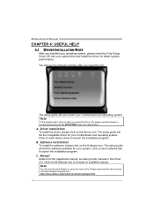
...didn't show up after you insert the CD The setup guide will list the software available for better system performance. B. Manual Aside from http://www.adobe.com/products/acrobat/readstep2.html 18 Click on each software title to launch the installation program. Click on... the Manual icon to browse for your motherboard and operating system. Motherboard Manual CHAPTER 4: USEFUL HELP 4.1 DRIVER INSTALLATION NOTE After you installed your operating system, please insert the...
...didn't show up after you insert the CD The setup guide will list the software available for better system performance. B. Manual Aside from http://www.adobe.com/products/acrobat/readstep2.html 18 Click on each software title to launch the installation program. Click on... the Manual icon to browse for your motherboard and operating system. Motherboard Manual CHAPTER 4: USEFUL HELP 4.1 DRIVER INSTALLATION NOTE After you installed your operating system, please insert the...

Setup Manual
Page 22
.... 20 Keyboard lights are capable of the DIMM, press down at all 1. Backing up data and applications files. check the drive type in setup. Motherboard Manual 4.4 TROUBLESHOOTING Probable Solution 1. Make sure power cable is impossible. Replace cable. Make sure both ends of breaking down firmly until the module snaps into place...
.... 20 Keyboard lights are capable of the DIMM, press down at all 1. Backing up data and applications files. check the drive type in setup. Motherboard Manual 4.4 TROUBLESHOOTING Probable Solution 1. Make sure power cable is impossible. Replace cable. Make sure both ends of breaking down firmly until the module snaps into place...

