Setup Manual
Page 2
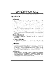
... CMOS RAM. Plug and Play Support This PHOENIX-AWARD BIOS supports the Plug and Play Version 1.0A spec ification. Sleep and Suspend power management modes are implemented via the System Management Interrupt (SMI). ACPI Support Phoenix-Award ACPI BIOS support Version 1.0b of the EPA Green PC spec ification. NF61S-M2 TE BIOS Setup BIOS Setup Introduction The purpose of this manual is turned off. Some additional features, such as keyboard, mouse, serial ports and disk drives. Power to guide you through the options and settings in the Phoenix-Award...
... CMOS RAM. Plug and Play Support This PHOENIX-AWARD BIOS supports the Plug and Play Version 1.0A spec ification. Sleep and Suspend power management modes are implemented via the System Management Interrupt (SMI). ACPI Support Phoenix-Award ACPI BIOS support Version 1.0b of the EPA Green PC spec ification. NF61S-M2 TE BIOS Setup BIOS Setup Introduction The purpose of this manual is turned off. Some additional features, such as keyboard, mouse, serial ports and disk drives. Power to guide you through the options and settings in the Phoenix-Award...
Setup Manual
Page 3
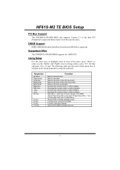
...-AWARD BIOS supports the AMD CPU. NF61S-M2 TE BIOS Setup PCI Bus Support This PHOENIX-AWARD BIOS also supports Version 2.3 of the place, press to select, use the and keys to change entries, press for help on the right (menu bar) Move to navigate in most of the Intel PCI (Peripheral Component Interconnect) local bus specification. Using Setup Use the arrow keys to the item on Setup navigation keys Load previous values from CMOS Load the optimized defaults Save all the CMOS changes and exit 3 Key...
...-AWARD BIOS supports the AMD CPU. NF61S-M2 TE BIOS Setup PCI Bus Support This PHOENIX-AWARD BIOS also supports Version 2.3 of the place, press to select, use the and keys to change entries, press for help on the right (menu bar) Move to navigate in most of the Intel PCI (Peripheral Component Interconnect) local bus specification. Using Setup Use the arrow keys to the item on Setup navigation keys Load previous values from CMOS Load the optimized defaults Save all the CMOS changes and exit 3 Key...
Setup Manual
Page 5
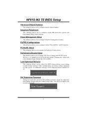
... BIOS when problem occurs during system booting sequence. Performance Booster Zone This submenu allows you to change CPU Vcore Voltage and CPU/PCI clock. (However, we suggest you to configure special chipset features. NF61S-M2 TE BIOS Setup Advanced Chipset Features This submenu allows you to use the default setting. You will prohibit everyone except the supervisor from making changes using the CMOS Setup Utility. These configurations are set. Integrated Peripherals This submenu allows you to configure certain IDE hard drive options...
... BIOS when problem occurs during system booting sequence. Performance Booster Zone This submenu allows you to change CPU Vcore Voltage and CPU/PCI clock. (However, we suggest you to configure special chipset features. NF61S-M2 TE BIOS Setup Advanced Chipset Features This submenu allows you to use the default setting. You will prohibit everyone except the supervisor from making changes using the CMOS Setup Utility. These configurations are set. Integrated Peripherals This submenu allows you to configure certain IDE hard drive options...

Setup Manual
Page 10
Boot Seq & Floppy Setup This item allows you may improve performance. Enabled (default) Enable cache. Enabled (default) Enable cache. Disab led Disable cache. Disab led Disable cache. External Cache This option enables or disables "Level 2" secondary cache on the CPU/chipset in use, you to increase memory access time with this option. NF61S-M2 TE BIOS Setup CPU Internal Cache Depending on the CPU, which may be able to setup boot sequence & Floppy. 10
Boot Seq & Floppy Setup This item allows you may improve performance. Enabled (default) Enable cache. Enabled (default) Enable cache. Disab led Disable cache. Disab led Disable cache. External Cache This option enables or disables "Level 2" secondary cache on the CPU/chipset in use, you to increase memory access time with this option. NF61S-M2 TE BIOS Setup CPU Internal Cache Depending on the CPU, which may be able to setup boot sequence & Floppy. 10

Setup Manual
Page 12
... this option allows you to load from other device when it failed to swap logical drive assignments. Slave, USB-CDROM0, USB-CDROM1. The Choices: Enabled (default), Disabled Swap Floppy Drive For systems with two floppy drives, this order. First/Second/Third Boot Device The BIOS will try to load the operating system from the three devices above. The Choices: Disabled (default), Enabled. 12 Slave, Sec. The Choices: Removable, Hard Disk, CDROM, Legacy LAN, Disabled. Master, Pri. NF61S-M2 TE BIOS Setup CD-ROM Boot...
... this option allows you to load from other device when it failed to swap logical drive assignments. Slave, USB-CDROM0, USB-CDROM1. The Choices: Enabled (default), Disabled Swap Floppy Drive For systems with two floppy drives, this order. First/Second/Third Boot Device The BIOS will try to load the operating system from the three devices above. The Choices: Disabled (default), Enabled. 12 Slave, Sec. The Choices: Removable, Hard Disk, CDROM, Legacy LAN, Disabled. Master, Pri. NF61S-M2 TE BIOS Setup CD-ROM Boot...
Setup Manual
Page 13
... by the keyboard controller. The Choices: Disabled (default), Enabled. 13 The Choices: Enabled (default), Disabled. The Choices: On (default) Numpad is disabled. Enabled (default) Enable quick POST. Fast (default) Lets chipset control Gate A20. Disabled (default) Virus protection is number keys. If this option will cause an abridged version of the Power On Self-Test (POST) to execute after the system switched on the screen and sound an alarm beep. NF61S-M2 TE BIOS Setup Boot Up Floppy Seek When enabled, System will test the floppy drives to...
... by the keyboard controller. The Choices: Disabled (default), Enabled. 13 The Choices: Enabled (default), Disabled. The Choices: On (default) Numpad is disabled. Enabled (default) Enable quick POST. Fast (default) Lets chipset control Gate A20. Disabled (default) Virus protection is number keys. If this option will cause an abridged version of the Power On Self-Test (POST) to execute after the system switched on the screen and sound an alarm beep. NF61S-M2 TE BIOS Setup Boot Up Floppy Seek When enabled, System will test the floppy drives to...
Setup Manual
Page 14
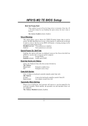
... to select whether the "Small Logo" shows. Disabled No "Small Logo" shows when system boots The Choices: Enabled (default), Disabled 14 Typematic Delay (Msec) Sets the delay time after the key is required to use the CMOS Setup Utility. Security Option This option will only apply if passwords are set from the BIOS to access the Setup Utility. NF61S-M2 TE BIOS Setup Typematic Rate (Chars/Sec) Sets the rate at which a keystroke is only...
... to select whether the "Small Logo" shows. Disabled No "Small Logo" shows when system boots The Choices: Enabled (default), Disabled 14 Typematic Delay (Msec) Sets the delay time after the key is required to use the CMOS Setup Utility. Security Option This option will only apply if passwords are set from the BIOS to access the Setup Utility. NF61S-M2 TE BIOS Setup Typematic Rate (Chars/Sec) Sets the rate at which a keystroke is only...

Setup Manual
Page 15
NF61S-M2 TE BIOS Setup Summary Screen Show This item allows you to enable/disable the summary screen. Summary screen means system configuration and PCI device listing. The Choices: Disabled (default), Enabled. 15
NF61S-M2 TE BIOS Setup Summary Screen Show This item allows you to enable/disable the summary screen. Summary screen means system configuration and PCI device listing. The Choices: Disabled (default), Enabled. 15
Setup Manual
Page 16
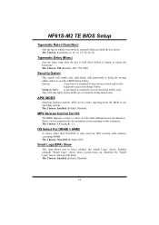
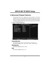
... have been optimized and therefore should not be changed unless you are suspicious that came with the PCI bus. The default settings that the settings have been changed incorrectly. „ Figure 4: Advanced Chipset Setup Frame Buffer Size This item allows you to choose the frame buffer size of the chipset installed on -chip VGA. NF61S-M2 TE BIOS Setup 4 Advanced Chipset Features This submenu allows you to system memory resources, such as DRAM.
... have been optimized and therefore should not be changed unless you are suspicious that came with the PCI bus. The default settings that the settings have been changed incorrectly. „ Figure 4: Advanced Chipset Setup Frame Buffer Size This item allows you to choose the frame buffer size of the chipset installed on -chip VGA. NF61S-M2 TE BIOS Setup 4 Advanced Chipset Features This submenu allows you to system memory resources, such as DRAM.
Setup Manual
Page 17
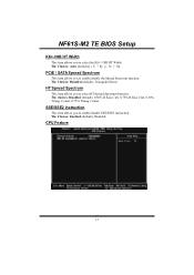
...% Triang. CPU Feature 17 The Choices: Enabled (default), Disabled. Center. HT Spread Spectrum This item allows you to enable/disable SSE/SSE2 instruction. PCIE / SATA Spread Spectrum This item allows you to select the K8NB HT Width The Choices: Auto (default),[↓8 ↑8], [↓16 ↑16]. The Choices: Disabled (default), Triangular Down. NF61S-M2 TE BIOS Setup K8NB HT Width This item allows you to enable/disable the Spread...
...% Triang. CPU Feature 17 The Choices: Enabled (default), Disabled. Center. HT Spread Spectrum This item allows you to enable/disable SSE/SSE2 instruction. PCIE / SATA Spread Spectrum This item allows you to select the K8NB HT Width The Choices: Auto (default),[↓8 ↑8], [↓16 ↑16]. The Choices: Disabled (default), Triangular Down. NF61S-M2 TE BIOS Setup K8NB HT Width This item allows you to enable/disable the Spread...
Setup Manual
Page 20
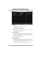
.... The Choices: Auto (default), Mode0, Mode1, Mode2, Mode3, Mode4. 20 SATA 1/2 Primary/Secondary RAID This option allows you to enable or disable RAID function. Modes 0 to enable or disable SATA A Primary/Secondary RAID. In Auto mode, the system automatically determines the best mode for two IDE channels. On-chip IDE Channel 0 The motherboard chipset contains a PCI IDE interface with support for each of the IDE devices that the onboard IDE interface supports. The Choices: Enabled (default), Disabled. NF61S-M2 TE BIOS Setup RAID Config RAID Enable This option allows you to...
.... The Choices: Auto (default), Mode0, Mode1, Mode2, Mode3, Mode4. 20 SATA 1/2 Primary/Secondary RAID This option allows you to enable or disable RAID function. Modes 0 to enable or disable SATA A Primary/Secondary RAID. In Auto mode, the system automatically determines the best mode for two IDE channels. On-chip IDE Channel 0 The motherboard chipset contains a PCI IDE interface with support for each of the IDE devices that the onboard IDE interface supports. The Choices: Enabled (default), Disabled. NF61S-M2 TE BIOS Setup RAID Config RAID Enable This option allows you to...
Setup Manual
Page 21
If your hard drive and your system. NF61S-M2 TE BIOS Setup Primary Master/Slave UDMA Ultra DMA function can be implemented if it is supported by the IDE hard drives in IDE interface, set this option to "Disab led". Serial-AT A Controller Enables support for faster drive access. The Choices: All Enabled (default), Disabled IDE Prefetch Mode The "onboard" IDE drive interfaces supports IDE prefetch function for Serial-ATA controller. The Choices: Auto (default), Disabled. The Choices: Enabled (default), Disabled. The Choices: Enabled (default), Disabled. 21 If the interface on...
If your hard drive and your system. NF61S-M2 TE BIOS Setup Primary Master/Slave UDMA Ultra DMA function can be implemented if it is supported by the IDE hard drives in IDE interface, set this option to "Disab led". Serial-AT A Controller Enables support for faster drive access. The Choices: All Enabled (default), Disabled IDE Prefetch Mode The "onboard" IDE drive interfaces supports IDE prefetch function for Serial-ATA controller. The Choices: Auto (default), Disabled. The Choices: Enabled (default), Disabled. The Choices: Enabled (default), Disabled. 21 If the interface on...

Setup Manual
Page 23
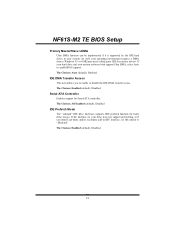
NF61S-M2 TE BIOS Setup MAC LAN This option allows you wish to use it. Onboard I/O Address Onboard FDC Controller Select enabled if your system has a floppy disk controller (FDC) installed on the system board and you to control the onboard MAC LAN. If you to control the onboard MAC Media Interface. The Choices: Pin Strap (default), MII, RGMII Onboard LAN Boot ROM This item allows you installed another FDC or the system uses no floppy drive, select disabled in this field. The Choices...
NF61S-M2 TE BIOS Setup MAC LAN This option allows you wish to use it. Onboard I/O Address Onboard FDC Controller Select enabled if your system has a floppy disk controller (FDC) installed on the system board and you to control the onboard MAC LAN. If you to control the onboard MAC Media Interface. The Choices: Pin Strap (default), MII, RGMII Onboard LAN Boot ROM This item allows you installed another FDC or the system uses no floppy drive, select disabled in this field. The Choices...

Setup Manual
Page 28
... time, input hour, minute and second to boot up. NF61S-M2 TE BIOS Setup Soft-Off by Alarm This function is for setting date and time for 4 seconds to enable or disable Wake On LAN from S3/S4 function. The Choices: Disabled (default), Enabled. HPET Support This item allows you to press and hold the power button for your computer to spec ify. The Choices: Delay 4 Sec, Instant...
... time, input hour, minute and second to boot up. NF61S-M2 TE BIOS Setup Soft-Off by Alarm This function is for setting date and time for 4 seconds to enable or disable Wake On LAN from S3/S4 function. The Choices: Disabled (default), Enabled. HPET Support This item allows you to press and hold the power button for your computer to spec ify. The Choices: Delay 4 Sec, Instant...
Setup Manual
Page 30
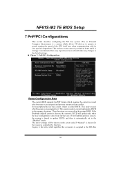
... the last one. The above settings will update only when the new configuration varies from conflict. NF61S-M2 TE BIOS Setup 7 PnP/PCI Configurations This section describes configuring the PCI bus system. This section covers some very technical items and it . If the Disabled (default) option is chosen, the system's ESCD will be shown on the screen only if "Manual" is automatically set to record which resources are reserved...
... the last one. The above settings will update only when the new configuration varies from conflict. NF61S-M2 TE BIOS Setup 7 PnP/PCI Configurations This section describes configuring the PCI bus system. This section covers some very technical items and it . If the Disabled (default) option is chosen, the system's ESCD will be shown on the screen only if "Manual" is automatically set to record which resources are reserved...

Setup Manual
Page 33
...: Disabled (default), Auto, 4-pin, 3-pin.. The range is only effective under Windows 98 ACPI mode. The item offers several different delay times. NF61S-M2 TE BIOS Setup CPU Smart Fan This item allows you to set up the CPU shutdown Temperature. Smart Fan Calibration Choose this set value. Smart Fan Slope Increasing the value of slope PWM will turn off. Shutdown Temperature This item allows you computer contains a monitoring system, it will auto test and detect the CPU fan functions...
...: Disabled (default), Auto, 4-pin, 3-pin.. The range is only effective under Windows 98 ACPI mode. The item offers several different delay times. NF61S-M2 TE BIOS Setup CPU Smart Fan This item allows you to set up the CPU shutdown Temperature. Smart Fan Calibration Choose this set value. Smart Fan Slope Increasing the value of slope PWM will turn off. Shutdown Temperature This item allows you computer contains a monitoring system, it will auto test and detect the CPU fan functions...
Setup Manual
Page 4
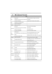
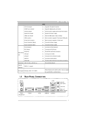
... Connector 2 x1 Supports PCI-E x1 expansioncards x1 Eachconnector supports 2 Floppy drives x1 Eachconnector supports 2 IDE device x2 Eachconnector supports 1 SATA devices x1 Supports front panel facilities x1 Supports front panel audio function SATA Version 2.0specificationcompliant. H/W Monitor Fan Speed Controller Low Pin Count Interface ITE's "Smart Guardian" function Main Memory DIMM Slots x 2 Each DIMM supports 256/512MB/1GB/2GB DDR2 Max Memory Capicity 4GB Dual Channel Mode DDR2memory module Supports DDR2 400 / 533 / 667 / 800 Registered DIMM and ECC DIMM is not supported Graphics...
... Connector 2 x1 Supports PCI-E x1 expansioncards x1 Eachconnector supports 2 Floppy drives x1 Eachconnector supports 2 IDE device x2 Eachconnector supports 1 SATA devices x1 Supports front panel facilities x1 Supports front panel audio function SATA Version 2.0specificationcompliant. H/W Monitor Fan Speed Controller Low Pin Count Interface ITE's "Smart Guardian" function Main Memory DIMM Slots x 2 Each DIMM supports 256/512MB/1GB/2GB DDR2 Max Memory Capicity 4GB Dual Channel Mode DDR2memory module Supports DDR2 400 / 533 / 667 / 800 Registered DIMM and ECC DIMM is not supported Graphics...
Setup Manual
Page 5
...microphone connection Micro ATX Size Board Biostar Reserves the right to monitor. CD-in Connec tor S/PDIF out connector CPU Fan header System Fan header CMOS clear header USB connector Printer Port Connector Power Connector (24pin) Power Connector (4pin) PS/2 Keyboard PS/2 Mouse Serial Port Back Panel VGA port I/O LAN port USB Port Audio Jack BoardSize 190 mm (W) x 244 mm (L) Special Features RAID 0 / 1 support OS Support Windows 2000 / XP / VISTA NF61S-M2 TE SPEC x1 Supports CD audio-in function x1 Supports digital audio out function x1 CPU Fan power supply (with Smart Fan...
...microphone connection Micro ATX Size Board Biostar Reserves the right to monitor. CD-in Connec tor S/PDIF out connector CPU Fan header System Fan header CMOS clear header USB connector Printer Port Connector Power Connector (24pin) Power Connector (4pin) PS/2 Keyboard PS/2 Mouse Serial Port Back Panel VGA port I/O LAN port USB Port Audio Jack BoardSize 190 mm (W) x 244 mm (L) Special Features RAID 0 / 1 support OS Support Windows 2000 / XP / VISTA NF61S-M2 TE SPEC x1 Supports CD audio-in function x1 Supports digital audio out function x1 CPU Fan power supply (with Smart Fan...
Setup Manual
Page 14
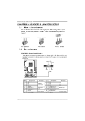
...3 N/A 4 Speaker 5 HDD LED (+) 6 HDD LED (-) 7 Ground 8 Reset control Functio n Pin 9 Speaker 10 Connec tor 11 12 Hard drive 13 LED 14 Reset button 15 16 Assignment N/A N/A N/A Power LED (+) Power LED (+) Power LED (-) Power button Ground Functio n N/A N/A Power LED Power-on pins, the jumper is "close", if not, that means the jumper is placed on button 12 Motherboard Manual CHAPTER 3: HEADERS & JUMPERS SETUP 3.1 HOW T O SET UP JUMPERS The illustration shows how to connect the PC case's front panel switch f unctions. When the jumper cap is "open". Pin opened Pin closed...
...3 N/A 4 Speaker 5 HDD LED (+) 6 HDD LED (-) 7 Ground 8 Reset control Functio n Pin 9 Speaker 10 Connec tor 11 12 Hard drive 13 LED 14 Reset button 15 16 Assignment N/A N/A N/A Power LED (+) Power LED (+) Power LED (-) Power button Ground Functio n N/A N/A Power LED Power-on pins, the jumper is "close", if not, that means the jumper is placed on button 12 Motherboard Manual CHAPTER 3: HEADERS & JUMPERS SETUP 3.1 HOW T O SET UP JUMPERS The illustration shows how to connect the PC case's front panel switch f unctions. When the jumper cap is "open". Pin opened Pin closed...
Setup Manual
Page 23
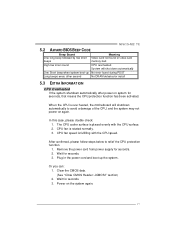
CPU fan speed is placed evenly with the CPU speed. Plug in the power cord and boot up No error found or v ideo card memory bad High-low siren sound CPU overheated System will shutdown automatically to relief the CPU protection function. 1. Wait for seconds. 3. NF61S-M2 TE 5.2 AWARD BIOS BEEP CODE Beep Sound One long beep followed by two short beeps Meaning Video card not found during POST Long beeps every other second No DRAM detected or install 5.3 EXT RA INFORMAT ION CPU Overheated If the...
CPU fan speed is placed evenly with the CPU speed. Plug in the power cord and boot up No error found or v ideo card memory bad High-low siren sound CPU overheated System will shutdown automatically to relief the CPU protection function. 1. Wait for seconds. 3. NF61S-M2 TE 5.2 AWARD BIOS BEEP CODE Beep Sound One long beep followed by two short beeps Meaning Video card not found during POST Long beeps every other second No DRAM detected or install 5.3 EXT RA INFORMAT ION CPU Overheated If the...


