Update Manual
Page 3
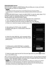
...during the Power-On Self Tests (POST) procedure while booting up , press key to start updating BIOS. 7. This utility only allows storage device with BIOSTAR BIOS Flasher 1. Updating BIOS with FAT32/16 format and single partition. 2. Power on board may be changed without notice. Press the [Y] key to... be slightly different from this manual. After entering the BIOS setup, please go to the Save & Exit, using the Restore Defaults function to load Optimized Defaults, and select Save...
...during the Power-On Self Tests (POST) procedure while booting up , press key to start updating BIOS. 7. This utility only allows storage device with BIOSTAR BIOS Flasher 1. Updating BIOS with FAT32/16 format and single partition. 2. Power on board may be changed without notice. Press the [Y] key to... be slightly different from this manual. After entering the BIOS setup, please go to the Save & Exit, using the Restore Defaults function to load Optimized Defaults, and select Save...
Setup Manual
Page 1
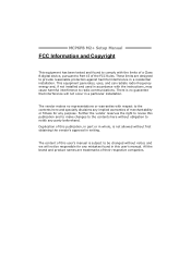
The content of this user's manual is subject to radio communications. This equipment generates, uses, and can radiate radio frequency energy and, if not installed and used in accordance with the ..., in part or in whole, is no representations or warranties with respect to provide reasonable protection against harmful interference in a residential installation. MCP6PB M2+ Setup Manual FCC Information and Copyright This equipment has been tested and found in this user...
The content of this user's manual is subject to radio communications. This equipment generates, uses, and can radiate radio frequency energy and, if not installed and used in accordance with the ..., in part or in whole, is no representations or warranties with respect to provide reasonable protection against harmful interference in a residential installation. MCP6PB M2+ Setup Manual FCC Information and Copyright This equipment has been tested and found in this user...
Setup Manual
Page 3
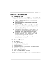
... lighting. „ Always disconnect the computer from power outlet before operation. „ Before you for ATX Case X 1 Installation Guide X 1 Fully Setup Driver CD X 1 (full version manual files inside) FDD Cable X 1 (optional) USB 2.0 Cable X1 (optional) Serial ATA Power Cable X 1 (optional) Note: The package contents may damage the equipment. „ Keep the...
... lighting. „ Always disconnect the computer from power outlet before operation. „ Before you for ATX Case X 1 Installation Guide X 1 Fully Setup Driver CD X 1 (full version manual files inside) FDD Cable X 1 (optional) USB 2.0 Cable X1 (optional) Serial ATA Power Cable X 1 (optional) Note: The package contents may damage the equipment. „ Keep the...
Setup Manual
Page 4
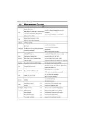
Motherboard Manual 1.3 MOTHERBOARD FEATURES SPEC Socket AM2 / AM2+ AMD 64 Architecture enables 32 and 64 bit AMD Athlon 64 / Athlon 64 FX / Athlon 64 x2 CPU computing / ...
Motherboard Manual 1.3 MOTHERBOARD FEATURES SPEC Socket AM2 / AM2+ AMD 64 Architecture enables 32 and 64 bit AMD Athlon 64 / Athlon 64 FX / Athlon 64 x2 CPU computing / ...
Setup Manual
Page 8
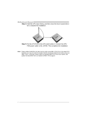
... the new system failed to the JCFAN. This completes the installation. In this case, please install one standard AM2 CPU to complete the installation. Motherboard Manual Step 4: Hold the CPU down firmly, and then close the lever toward direct B to boot your system, and update the latest BIOS from our website...
... the new system failed to the JCFAN. This completes the installation. In this case, please install one standard AM2 CPU to complete the installation. Motherboard Manual Step 4: Hold the CPU down firmly, and then close the lever toward direct B to boot your system, and update the latest BIOS from our website...

Setup Manual
Page 10
Insert the DIMM vertically and firmly into the slot until the retaining chip snap back in place and the DIMM is properly seated. 8 Align a DIMM on the slot so that the notch on the DIMM matches the break on the Slot. 2. Memory Modules 1. Unlock a DIMM slot by pressing the retaining clips outward. DIM MA1 DIM MB1 Motherboard Manual 2.3 INSTALLING SYSTEM MEMORY A.
Insert the DIMM vertically and firmly into the slot until the retaining chip snap back in place and the DIMM is properly seated. 8 Align a DIMM on the slot so that the notch on the DIMM matches the break on the Slot. 2. Memory Modules 1. Unlock a DIMM slot by pressing the retaining clips outward. DIM MA1 DIM MB1 Motherboard Manual 2.3 INSTALLING SYSTEM MEMORY A.

Setup Manual
Page 12
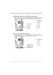
This connector supports the provided floppy drive ribbon cable. 2 34 1 33 IDE: IDE/ATAPI Connector The motherboard has a 32-bit Enhanced PCI IDE Controller that supports 360K, 720K, 1.2M, 1.44M and 2.88M floppy disk types. The IDE connector can connect a master and a slave drive, so you can connect up to two drives. 40 39 21 10 Motherboard Manual 2.4 CONNECTORS AND SLOTS FDD: Floppy Disk Connector The motherboard provides a standard floppy disk connector that provides PIO Mode 0~4, Bus Master, and Ultra DMA 33/66/100/133 functionality.
This connector supports the provided floppy drive ribbon cable. 2 34 1 33 IDE: IDE/ATAPI Connector The motherboard has a 32-bit Enhanced PCI IDE Controller that supports 360K, 720K, 1.2M, 1.44M and 2.88M floppy disk types. The IDE connector can connect a master and a slave drive, so you can connect up to two drives. 40 39 21 10 Motherboard Manual 2.4 CONNECTORS AND SLOTS FDD: Floppy Disk Connector The motherboard provides a standard floppy disk connector that provides PIO Mode 0~4, Bus Master, and Ultra DMA 33/66/100/133 functionality.
Setup Manual
Page 14
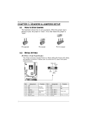
... 13 LED 14 Reset button 15 16 Assignment N/A N/A N/A Power LED (+) Power LED (+) Power LED (-) Power button Ground Function N/A N/A Power LED Power-on button 12 Motherboard Manual CHAPTER 3: HEADERS & JUMPERS SETUP 3.1 HOW TO SETUP JUMPERS The illustration shows how to connect the PC case's front panel switch functions.
... 13 LED 14 Reset button 15 16 Assignment N/A N/A N/A Power LED (+) Power LED (+) Power LED (-) Power button Ground Function N/A N/A Power LED Power-on button 12 Motherboard Manual CHAPTER 3: HEADERS & JUMPERS SETUP 3.1 HOW TO SETUP JUMPERS The illustration shows how to connect the PC case's front panel switch functions.
Setup Manual
Page 16
... The motherboard has a PCI to connect additional USB cable on the PC front panel, and also can be connected with transfer rate of 3.0Gb/s. Motherboard Manual JUSB2/JUSB3: Headers for USB 2.0 Ports at Front Panel These headers allow user to SATA Controller with 2 channels SATA interface, it satisfies the SATA 2.0 spec...
... The motherboard has a PCI to connect additional USB cable on the PC front panel, and also can be connected with transfer rate of 3.0Gb/s. Motherboard Manual JUSB2/JUSB3: Headers for USB 2.0 Ports at Front Panel These headers allow user to SATA Controller with 2 channels SATA interface, it satisfies the SATA 2.0 spec...
Setup Manual
Page 18
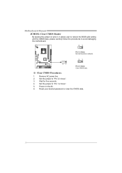
Set the jumper to "Pin 2-3 close ". 5. Set the jumper to "Pin 1-2 close ". 3. Power on pin2-3, it allows user to restore the BIOS safe setting and the CMOS data, please carefully follow the procedures to avoid damaging the motherboard. 31 Pin 1-2 Close: Normal Operation (default). 31 31 Pin 2-3 Close: Clear CMOS data. ※ Clear CMOS Procedures: 1. Wait for five seconds. 4. Motherboard Manual JCMOS1: Clear CMOS Header By placing the jumper on the AC. 6. Reset your desired password or clear the CMOS data. 16 Remove AC power line. 2.
Set the jumper to "Pin 2-3 close ". 5. Set the jumper to "Pin 1-2 close ". 3. Power on pin2-3, it allows user to restore the BIOS safe setting and the CMOS data, please carefully follow the procedures to avoid damaging the motherboard. 31 Pin 1-2 Close: Normal Operation (default). 31 31 Pin 2-3 Close: Clear CMOS data. ※ Clear CMOS Procedures: 1. Wait for five seconds. 4. Motherboard Manual JCMOS1: Clear CMOS Header By placing the jumper on the AC. 6. Reset your desired password or clear the CMOS data. 16 Remove AC power line. 2.
Setup Manual
Page 20
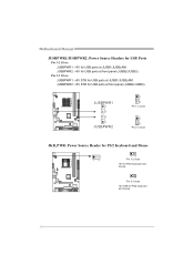
JUSBPWR2: +5V STB for USB ports at JUSB1/JUSBLAN1. Motherboard Manual JUSBPWR1/JUSBPWR2: Power Source Headers for USB Ports Pin 1-2 Close: JUSBPWR1: +5V for USB ports at front panel (JUSB2/JUSB3). Pin 2-3 Close: JUSBPWR1: +5V STB for USB ports at front panel (JUSB2/JUSB3). JUSBPWR2: +5V for PS/2 keyboard and mouse. 18 JUSBPWR1 1 3 3 1 JUSBPWR2 1 3 Pin 1-2 close 1 3 Pin 2-3 close JKB_PWR: Power Source Header for PS/2 Keyboard and Mouse 1 3 1 3 Pin 1-2 close +5V for PS/2 keyboard and mouse. 1 3 Pin 2-3 close +5V STB for USB ports at JUSB1/JUSBLAN1.
JUSBPWR2: +5V STB for USB ports at JUSB1/JUSBLAN1. Motherboard Manual JUSBPWR1/JUSBPWR2: Power Source Headers for USB Ports Pin 1-2 Close: JUSBPWR1: +5V for USB ports at front panel (JUSB2/JUSB3). Pin 2-3 Close: JUSBPWR1: +5V STB for USB ports at front panel (JUSB2/JUSB3). JUSBPWR2: +5V for PS/2 keyboard and mouse. 18 JUSBPWR1 1 3 3 1 JUSBPWR2 1 3 Pin 1-2 close 1 3 Pin 2-3 close JKB_PWR: Power Source Header for PS/2 Keyboard and Mouse 1 3 1 3 Pin 1-2 close +5V for PS/2 keyboard and mouse. 1 3 Pin 2-3 close +5V STB for USB ports at JUSB1/JUSBLAN1.

Setup Manual
Page 22
... of one drive fail, the controller switches to the other drive. Drawbacks: Requires 2 drives for small databases or any other application that eliminates tedious manual backups to more expensive and less reliable media. Should one drive. Block 1 Block 2 Block 3 20 Block 1 Block 2 Block 3 Motherboard...
... of one drive fail, the controller switches to the other drive. Drawbacks: Requires 2 drives for small databases or any other application that eliminates tedious manual backups to more expensive and less reliable media. Should one drive. Block 1 Block 2 Block 3 20 Block 1 Block 2 Block 3 Motherboard...
Setup Manual
Page 23
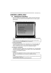
... the Fully Setup Driver CD into your optical drive and install the driver for your system, click on each device driver to open the manual file. The setup guide will need Acrobat Reader to launch the installation program. Note: You will list the software available for better system ...didn't show up after you insert the Driver CD, please use file browser to browse for your motherboard and operating system. Click on the Manual icon to locate and execute the file SETUP.EXE under your motherboard and operating system. C. The setup guide will auto detect your optical drive...
... the Fully Setup Driver CD into your optical drive and install the driver for your system, click on each device driver to open the manual file. The setup guide will need Acrobat Reader to launch the installation program. Note: You will list the software available for better system ...didn't show up after you insert the Driver CD, please use file browser to browse for your motherboard and operating system. Click on the Manual icon to locate and execute the file SETUP.EXE under your motherboard and operating system. C. The setup guide will auto detect your optical drive...
Setup Manual
Page 24
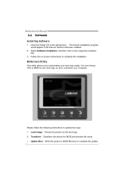
...;Transform the picture for BIOS and preview the result. 3. You can choose JPG or BMP as your boot logo so as the boot logo. 2. Motherboard Manual 5.2 SOFTWARE Installing Software 1. Select Software Installation, and then click on -screen instructions to the optical drive.
...;Transform the picture for BIOS and preview the result. 3. You can choose JPG or BMP as your boot logo so as the boot logo. 2. Motherboard Manual 5.2 SOFTWARE Installing Software 1. Select Software Installation, and then click on -screen instructions to the optical drive.
Setup Manual
Page 26
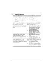
Motherboard Manual 5.5 TROUBLESHOOTING Probable Solution 1. Make sure power cable is inoperative. Contact technical support. 2. All hard disks are capable of the power supply does not 2. drive. Hard ...
Motherboard Manual 5.5 TROUBLESHOOTING Probable Solution 1. Make sure power cable is inoperative. Contact technical support. 2. All hard disks are capable of the power supply does not 2. drive. Hard ...

Setup Manual
Page 44
Motherboard Manual JAPANESE 仕様 Socket AM2 / AM2+ AMD 64 32ビットと64 AMD Athlon 64 / Athlon 64 FX / Althlon 64 能です ...
Motherboard Manual JAPANESE 仕様 Socket AM2 / AM2+ AMD 64 32ビットと64 AMD Athlon 64 / Athlon 64 FX / Althlon 64 能です ...
Bios Manual
Page 2
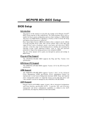
... do without accessing programs from a disk. Power management features are supported. MCP6PB M2+ BIOS Setup BIOS Setup Introduction The purpose of this manual is turned off. Basic Input-Output System (BIOS) determines what a computer can also be managed by Microsoft, Intel and Toshiba. 2 ...basic system configuration and save these settings to guide you through the options and settings in the ACPI specification, developed by this manual will to CMOS RAM. Sleep and Suspend power management modes are implemented via the System Management Interrupt (SMI). ACPI Support ...
... do without accessing programs from a disk. Power management features are supported. MCP6PB M2+ BIOS Setup BIOS Setup Introduction The purpose of this manual is turned off. Basic Input-Output System (BIOS) determines what a computer can also be managed by Microsoft, Intel and Toshiba. 2 ...basic system configuration and save these settings to guide you through the options and settings in the ACPI specification, developed by this manual will to CMOS RAM. Sleep and Suspend power management modes are implemented via the System Management Interrupt (SMI). ACPI Support ...
Bios Manual
Page 4
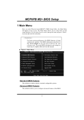
... settings on the screen. MCP6PB M2+ BIOS Setup 1 Main Menu Once you to configure advanced features of the BIOS. 4 The BIOS information described in this manual. „ Figure 1: Main Menu Standard CMOS Features This submenu contains industry standard configurable options. WARNING !! The Main Menu allows you to accept and enter the... on board may be slightly different from several setup functions. Use the arrow keys to select among the items and press to select from this manual (Figure 1, 2, 3, 4, 5, 6, 7, 8, 9) is being continuously updated.
... settings on the screen. MCP6PB M2+ BIOS Setup 1 Main Menu Once you to configure advanced features of the BIOS. 4 The BIOS information described in this manual. „ Figure 1: Main Menu Standard CMOS Features This submenu contains industry standard configurable options. WARNING !! The Main Menu allows you to accept and enter the... on board may be slightly different from several setup functions. Use the arrow keys to select among the items and press to select from this manual (Figure 1, 2, 3, 4, 5, 6, 7, 8, 9) is being continuously updated.
Bios Manual
Page 30
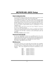
...conflict. The system needs to record and update ESCD to it. The Choices: Disabled (default), Enabled. The Choices: Auto (ESCD) (default), Manual. This node records which resources are assigned to the memory locations. Legacy is the term, which signifies that a resource is assigned to the ISA... the system interrupts. The above settings will be shown on the type of device using the interrupt. By Choosing "Manual", the user will allow you to " Manual". Be sure that will need to the "Disabled" mode. IRQ Resources This submenu will detect the system resources and...
...conflict. The system needs to record and update ESCD to it. The Choices: Disabled (default), Enabled. The Choices: Auto (ESCD) (default), Manual. This node records which resources are assigned to the memory locations. Legacy is the term, which signifies that a resource is assigned to the ISA... the system interrupts. The above settings will be shown on the type of device using the interrupt. By Choosing "Manual", the user will allow you to " Manual". Be sure that will need to the "Disabled" mode. IRQ Resources This submenu will detect the system resources and...

Bios Manual
Page 37
...: Enabled (default), Disabled. Memclock tri-stating The Choices: Disabled (default), Enabled. 37 MCP6PB M2+ BIOS Setup DRAM Configuration Timing Mode The Choices: Auto (default), MaxMemClk, Manual.
...: Enabled (default), Disabled. Memclock tri-stating The Choices: Disabled (default), Enabled. 37 MCP6PB M2+ BIOS Setup DRAM Configuration Timing Mode The Choices: Auto (default), MaxMemClk, Manual.

