
M6TSU user's manual
Page 4
Contents 1.6 Connectors, Headers & Jumpers 1-16 1.6.1 Front Panel Connector: JPANEL1 1-17 1.6.2 ATX 20-pin Power Connector: JATXPWR1 1-19 1.6.3 DIMM Power Header: JDIMMPWR1 1-19 1.6.4 Hard Disk Connectors: IDE1/IDE2 1-20 1.6.5 Floppy Disk Connector: FDD1 1-20 1.6.6 Wake On LAN Header: JWOL1 1-20 1.6.7 CMOS Function Selection: JCMOS1 1-21 1.6.8 Front USB Header: JUSB2 1-21 1.7 Back Panel Connectors 1-22 1.7.1 PS/2 Mouse / Keyboard Connectors: JKBMS1 1-22 1.7.2 USB Connector: JUSB1 1-23 1.7.3 Serial and Parallel Interface Ports 1-24 1.7.3.1 The Serial Interface: JCOM1/JCOM2 1-24 ...
Contents 1.6 Connectors, Headers & Jumpers 1-16 1.6.1 Front Panel Connector: JPANEL1 1-17 1.6.2 ATX 20-pin Power Connector: JATXPWR1 1-19 1.6.3 DIMM Power Header: JDIMMPWR1 1-19 1.6.4 Hard Disk Connectors: IDE1/IDE2 1-20 1.6.5 Floppy Disk Connector: FDD1 1-20 1.6.6 Wake On LAN Header: JWOL1 1-20 1.6.7 CMOS Function Selection: JCMOS1 1-21 1.6.8 Front USB Header: JUSB2 1-21 1.7 Back Panel Connectors 1-22 1.7.1 PS/2 Mouse / Keyboard Connectors: JKBMS1 1-22 1.7.2 USB Connector: JUSB1 1-23 1.7.3 Serial and Parallel Interface Ports 1-24 1.7.3.1 The Serial Interface: JCOM1/JCOM2 1-24 ...
M6TSU user's manual
Page 9
... 2.0, 3.3V or 1.5V signaling. LPC I/O Built-in Onboard − LPC Interface. − PC98, PC99 Compliant. − Game Port Interface. 1-3 BUS Slots − Provides six PCI Bus slots, one CNR slot (slave only) and one AGP Bus slot. Chapter1 Motherboard Description − Wakes up by BIOS. Accelerated Graphics Port (AGP) − Supports AGP 2.0 including 4X AGP data transfers. − High priority access support. − Hierarchical PCI configuration mechanism. − Supports via dual mode buffers to RAM) support.
... 2.0, 3.3V or 1.5V signaling. LPC I/O Built-in Onboard − LPC Interface. − PC98, PC99 Compliant. − Game Port Interface. 1-3 BUS Slots − Provides six PCI Bus slots, one CNR slot (slave only) and one AGP Bus slot. Chapter1 Motherboard Description − Wakes up by BIOS. Accelerated Graphics Port (AGP) − Supports AGP 2.0 including 4X AGP data transfers. − High priority access support. − Hierarchical PCI configuration mechanism. − Supports via dual mode buffers to RAM) support.

M6TSU user's manual
Page 10
...Flash Memory interface. − Automatically fine tunes to 4 IDE devices. (Coexist with on Parallel Port Pins. Supports 360KB, 720KB, 1.2MB, 1.44MB, and 2.88MB floppy disk drives. − Enhanced Digital Data Separator. − Serial Ports. Chapter1 Motherboard Description − MPU-401 MDI Support. − Intelligent Auto Power Management. − 2.88MB Super I/O Floppy Disk Controller. − Floppy Disk Available on -board IDE) − Supports Hard Drive with capacity larger than 30GB. − RAID function supported (RAID 0,1,0+1). − Supports the most popular Windows...
...Flash Memory interface. − Automatically fine tunes to 4 IDE devices. (Coexist with on Parallel Port Pins. Supports 360KB, 720KB, 1.2MB, 1.44MB, and 2.88MB floppy disk drives. − Enhanced Digital Data Separator. − Serial Ports. Chapter1 Motherboard Description − MPU-401 MDI Support. − Intelligent Auto Power Management. − 2.88MB Super I/O Floppy Disk Controller. − Floppy Disk Available on -board IDE) − Supports Hard Drive with capacity larger than 30GB. − RAID function supported (RAID 0,1,0+1). − Supports the most popular Windows...

M6TSU user's manual
Page 22
Noticeably, a jumper has two or more pins that can be covered by a plastic jumper cap, allowing you lots of capabilities such as power supply, front panel signal revelation, IDE hard disk connection, floppy disk connection, Wake On LAN function and Front USB connection. Chapter1 Motherboard Description 1.6 Connectors, Headers & Jumpers The connectors, headers and jumpers introduced below provide you to select different system options. 1 JWOL1 JATXPWR1 JDIMMPWR1 IDE1 IDE2 FDD1 1 JCMOS1 RAID2 RAID1 JPANEL1 1 JUSB2 1-16
Noticeably, a jumper has two or more pins that can be covered by a plastic jumper cap, allowing you lots of capabilities such as power supply, front panel signal revelation, IDE hard disk connection, floppy disk connection, Wake On LAN function and Front USB connection. Chapter1 Motherboard Description 1.6 Connectors, Headers & Jumpers The connectors, headers and jumpers introduced below provide you to select different system options. 1 JWOL1 JATXPWR1 JDIMMPWR1 IDE1 IDE2 FDD1 1 JCMOS1 RAID2 RAID1 JPANEL1 1 JUSB2 1-16
M6TSU user's manual
Page 24
Sleep Button (Green Button) This connector is used to attach to an infrared sensing device. The LED will cause the motherboard to reset and run the POST (Power On Self Test). HDD LED (Hard Disk LED Connector) This connector can be attached to an LED on the front panel of a computer case. APM (Advanced Power Management) must pull the Power Button pin to ground for at least 50 ms to signal the power supply to switch on or off...
Sleep Button (Green Button) This connector is used to attach to an infrared sensing device. The LED will cause the motherboard to reset and run the POST (Power On Self Test). HDD LED (Hard Disk LED Connector) This connector can be attached to an LED on the front panel of a computer case. APM (Advanced Power Management) must pull the Power Button pin to ground for at least 50 ms to signal the power supply to switch on or off...
M6TSU user's manual
Page 26
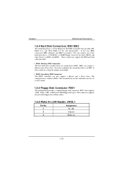
... configuration is similar to IDE1 and IDE2. Assignment 1 5V_SB 2 Ground 3 Wake up to four hard disk drives, a CD-ROM, a 120MB Floppy (reserved for future BIOS) and other devices to IDE1. Chapter1 Motherboard Description 1.6.4 Hard Disk Connectors: IDE1/IDE2 The motherboard has a 32-bit Enhanced, PCI IDE Controller that supports 360K, 720K, 1.2M, 1.44M and 2.88M floppy disk types. IDE2 (Secondary IDE Connector) The IDE2 controller can connect a Master and a Slave drive. This connector supports the provided floppy drive ribbon cables. 1.6.6 Wake On LAN Header: JWOL1 Pin...
... configuration is similar to IDE1 and IDE2. Assignment 1 5V_SB 2 Ground 3 Wake up to four hard disk drives, a CD-ROM, a 120MB Floppy (reserved for future BIOS) and other devices to IDE1. Chapter1 Motherboard Description 1.6.4 Hard Disk Connectors: IDE1/IDE2 The motherboard has a 32-bit Enhanced, PCI IDE Controller that supports 360K, 720K, 1.2M, 1.44M and 2.88M floppy disk types. IDE2 (Secondary IDE Connector) The IDE2 controller can connect a Master and a Slave drive. This connector supports the provided floppy drive ribbon cables. 1.6.6 Wake On LAN Header: JWOL1 Pin...
M6TSU user's manual
Page 36
... is turned off. Sleep and Suspend power management modes are implemented via the System Management Interrupt (SMI). EPA Green PC Support This AWARD BIOS supports Version 1.03 of the Advanced Power Management (APM) specification. Power to the hard disk drives and video monitors can be managed by this manual is intended to modify the basic system configuration. Plug and Play Support These AWARD BIOS supports the Plug and Play Version 1.0A specification. Power management features are supported. Chapter 2 BIOS Setup 2. The BIOS...
... is turned off. Sleep and Suspend power management modes are implemented via the System Management Interrupt (SMI). EPA Green PC Support This AWARD BIOS supports Version 1.03 of the Advanced Power Management (APM) specification. Power to the hard disk drives and video monitors can be managed by this manual is intended to modify the basic system configuration. Plug and Play Support These AWARD BIOS supports the Plug and Play Version 1.0A specification. Power management features are supported. Chapter 2 BIOS Setup 2. The BIOS...

M6TSU user's manual
Page 45
... . On (default) Numpad is activated. Disabled Normal POST. Typematic Rate (Chars/Sec) Sets the rate at a rate determined by the keyboard controller. Processor Number Feature The Intel processor serial number control option. Enabled (default) Enable quick POST. State after you hold the key down , the keystroke will display a warning message on . Virus protection is number keys. Disabled (default) Enabled Virus protection is used to protect the IDE Hard Disk boot sector. Chapter 2 BIOS Setup Virus Warning This option allows...
... . On (default) Numpad is activated. Disabled Normal POST. Typematic Rate (Chars/Sec) Sets the rate at a rate determined by the keyboard controller. Processor Number Feature The Intel processor serial number control option. Enabled (default) Enable quick POST. State after you hold the key down , the keystroke will display a warning message on . Virus protection is number keys. Disabled (default) Enabled Virus protection is used to protect the IDE Hard Disk boot sector. Chapter 2 BIOS Setup Virus Warning This option allows...
M6TSU user's manual
Page 46
... system. OS Select For DRAM > 64MB A choice other than Non-OS2 is held down before it begins to repeat the keystroke. The Choices: Enabeld (default), Disabled MPS Version Control For OS The BIOS supports versions 1.1 and 1.4 of the Intel multiprocessor specification. Chapter 2 BIOS Setup Sets the delay time after the key is only used for the system to boot and is required to access the Setup Utility only.
... system. OS Select For DRAM > 64MB A choice other than Non-OS2 is held down before it begins to repeat the keystroke. The Choices: Enabeld (default), Disabled MPS Version Control For OS The BIOS supports versions 1.1 and 1.4 of the Intel multiprocessor specification. Chapter 2 BIOS Setup Sets the delay time after the key is only used for the system to boot and is required to access the Setup Utility only.

M6TSU user's manual
Page 47
... 4. This chipset manages bus speeds and access to this memory area, a system error may result. It also coordinates communications with your system. The default settings that the settings have been changed incorrectly. Advanced Chipset Setup System BIOS Cacheable Selecting Enabled allows caching of the chipset installed on your system have been optimized and therefore should not be changed unless you to configure the specific features of the system BIOS ROM at...
... 4. This chipset manages bus speeds and access to this memory area, a system error may result. It also coordinates communications with your system. The default settings that the settings have been changed incorrectly. Advanced Chipset Setup System BIOS Cacheable Selecting Enabled allows caching of the chipset installed on your system have been optimized and therefore should not be changed unless you to configure the specific features of the system BIOS ROM at...
M6TSU user's manual
Page 49
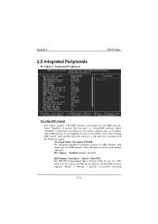
... two IDE channels. Modes 0 through 4 provide successively increased 2-14 The Choices: Enabled (default), Disabled. Select "Disabled" to activate the first and / or second IDE interface. Select Enabled to the "Onchip IDE Control" label and then press the enter key, it will take you highlight the literal "Press Enter" next to activate each of the IDE devices that the onboard IDE interface supports. Integrated Peripherals BIOS Setup On-Chip IDE Control The chipset contains a PCI IDE interface with support...
... two IDE channels. Modes 0 through 4 provide successively increased 2-14 The Choices: Enabled (default), Disabled. Select "Disabled" to activate the first and / or second IDE interface. Select Enabled to the "Onchip IDE Control" label and then press the enter key, it will take you highlight the literal "Press Enter" next to activate each of the IDE devices that the onboard IDE interface supports. Integrated Peripherals BIOS Setup On-Chip IDE Control The chipset contains a PCI IDE interface with support...

M6TSU user's manual
Page 51
... allows you to determine which Infrared (IR) function of onboard I /O chip. Onboard Serial Port 1/Port 2 Select an address and corresponding interrupt for the first and second serial ports. The Choices: Normal (default), ASKIR, IrDA. The Choices: Enabled (default), Disabled. UR2 Duplex Mode Select the value required by the IR device connected to support AC97 Audio/Modem. Chapter 2 BIOS Setup This item allows you to decide to enable/ disable to the IR...
... allows you to determine which Infrared (IR) function of onboard I /O chip. Onboard Serial Port 1/Port 2 Select an address and corresponding interrupt for the first and second serial ports. The Choices: Normal (default), ASKIR, IrDA. The Choices: Enabled (default), Disabled. UR2 Duplex Mode Select the value required by the IR device connected to support AC97 Audio/Modem. Chapter 2 BIOS Setup This item allows you to decide to enable/ disable to the IR...

M6TSU user's manual
Page 59
... default settings. PnP/PCI Configurations Reset Configuration Data The system BIOS supports the PnP feature which requires the system to operate at speeds nearing the speed of the CPU itself uses when communicating with its own special components. If the Disabled (default) option is called ESCD. Figure 7. If the Enabled option is chosen, the system is forced to update ESCDs and then is strongly recommended that only experienced users...
... default settings. PnP/PCI Configurations Reset Configuration Data The system BIOS supports the PnP feature which requires the system to operate at speeds nearing the speed of the CPU itself uses when communicating with its own special components. If the Disabled (default) option is called ESCD. Figure 7. If the Enabled option is chosen, the system is forced to update ESCDs and then is strongly recommended that only experienced users...

M6TSU user's manual
Page 61
... this option. In this case, the PCI VGA controller should not respond to the Write, it to their display as a way to provide boot information and VGA compatibility. Enabled Enables the function. 2-26 In PCI based systems, where the VGA controller is on the PCI bus and a non-VGA graphic controller is in the palette of the VGA controller. Disabled (default) Disables the function. However, the color information coming from the VGA controller is drawn from a VGA controller...
... this option. In this case, the PCI VGA controller should not respond to the Write, it to their display as a way to provide boot information and VGA compatibility. Enabled Enables the function. 2-26 In PCI based systems, where the VGA controller is on the PCI bus and a non-VGA graphic controller is in the palette of the VGA controller. Disabled (default) Disables the function. However, the color information coming from the VGA controller is drawn from a VGA controller...
M6TSU user's manual
Page 66
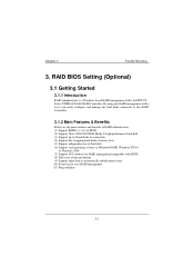
... benefits of RAID Administrator. (1) Support RAID 0, 1,0+1 & JBOD (2) Support Ultra ATA100(UDMA Mode 5) high performance hard disk (3) Support up to 4 hard disks in connection (4) Support hot-swapping hard disks of mirror array (5) Support independent use of hard disk (6) Support such operating systems as Windows98/ME, Windows NT4.0 & Windows 2000 (7) Support GUI software for RAID management(compatible with BIOS) (8) Disk error alarm mechanism (9) Support spare disk to automatically rebuild mirror array (10) Event log for HPT370 Series UDMA/ATA100 RAID Controller. RAID BIOS Setting (Optional...
... benefits of RAID Administrator. (1) Support RAID 0, 1,0+1 & JBOD (2) Support Ultra ATA100(UDMA Mode 5) high performance hard disk (3) Support up to 4 hard disks in connection (4) Support hot-swapping hard disks of mirror array (5) Support independent use of hard disk (6) Support such operating systems as Windows98/ME, Windows NT4.0 & Windows 2000 (7) Support GUI software for RAID management(compatible with BIOS) (8) Disk error alarm mechanism (9) Support spare disk to automatically rebuild mirror array (10) Event log for HPT370 Series UDMA/ATA100 RAID Controller. RAID BIOS Setting (Optional...
M6TSU user's manual
Page 68
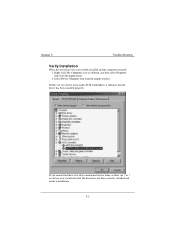
or ! Chapter 3 Trouble Shooting Verify Installation When the driver has been successfully installed and the computer restarted: 1. Select Device Manager item from the popup menu. 2. on desktop, and then select Property item from the popup window. If there are ? If you cannot find these two above-mentioned device items, or there are two device items under SCSI Controllers, it indicates that the driver has been installed properly. Right-click My Computer icon on device icon, it indicates that the driver has not been correctly installed and needs reinstallation. 3-3
or ! Chapter 3 Trouble Shooting Verify Installation When the driver has been successfully installed and the computer restarted: 1. Select Device Manager item from the popup menu. 2. on desktop, and then select Property item from the popup window. If there are ? If you cannot find these two above-mentioned device items, or there are two device items under SCSI Controllers, it indicates that the driver has been installed properly. Right-click My Computer icon on device icon, it indicates that the driver has not been correctly installed and needs reinstallation. 3-3
M6TSU user's manual
Page 70
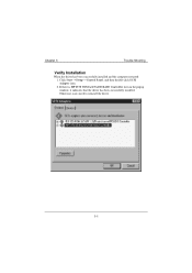
Otherwise, users need to reinstall the driver. 3-5 Click Start-->Setup-->Control Panel, and then double-click SCSI Adapter item. 2. If there is HPT370 UDMA/ATA100 RAID Controller item in the popup window, it indicates that the driver has been successfully installed. Chapter 3 Trouble Shooting Verify Installation When the driver has been successfully installed and the computer restarted: 1.
Otherwise, users need to reinstall the driver. 3-5 Click Start-->Setup-->Control Panel, and then double-click SCSI Adapter item. 2. If there is HPT370 UDMA/ATA100 RAID Controller item in the popup window, it indicates that the driver has been successfully installed. Chapter 3 Trouble Shooting Verify Installation When the driver has been successfully installed and the computer restarted: 1.

M6TSU user's manual
Page 71
.../Troubleshoot a device, then click Next to install the driver. Please insert the floppy disk of device types, select SCSI and RAID controllers, then click Next to continue. 4. In the follow-on window of driver and follow -on window, Click Next to type Winnt and install, after files have been copied and the computer 3-6 Please select No, I want to select the hardware from the CD-ROM drive, please F6 key...
.../Troubleshoot a device, then click Next to install the driver. Please insert the floppy disk of device types, select SCSI and RAID controllers, then click Next to continue. 4. In the follow-on window of driver and follow -on window, Click Next to type Winnt and install, after files have been copied and the computer 3-6 Please select No, I want to select the hardware from the CD-ROM drive, please F6 key...
M6TSU user's manual
Page 73
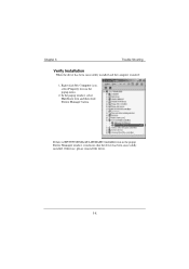
If there is HPT370 UDMA/ATA100 RAID Controller item in the popup menu. 2. Otherwise, please reinstall the driver. 3-8 Chapter 3 Trouble Shooting Verify Installation When the driver has been successfully installed and the computer restarted: 1. In the popup window, select Hardware item and then click Device Manager button. Right-click My Computer icon, select Property item in the popup Device Manager window, it indicates that the driver has been successfully installed.
If there is HPT370 UDMA/ATA100 RAID Controller item in the popup menu. 2. Otherwise, please reinstall the driver. 3-8 Chapter 3 Trouble Shooting Verify Installation When the driver has been successfully installed and the computer restarted: 1. In the popup window, select Hardware item and then click Device Manager button. Right-click My Computer icon, select Property item in the popup Device Manager window, it indicates that the driver has been successfully installed.
M6TSU user's manual
Page 104
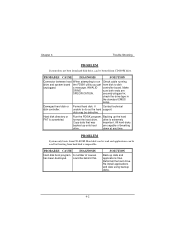
... the hard drive. Chapter 4 Trouble Shooting PROBLEM System does not boot from hard disk drive, can be used but booting from CD-ROM. a message, INVALID controller board. All hard disks backed up onto hard are SPECIFICATION. PROBLEM System only boots from hard disk is scrambled. check the drive type in ; if Contact technical unable to run Check cable running drive and system board the FDISK utility you get from CD-ROM drive. down at any time. PROBABLE CAUSE DIAGNOSIS Hard disk boot...
... the hard drive. Chapter 4 Trouble Shooting PROBLEM System does not boot from hard disk drive, can be used but booting from CD-ROM. a message, INVALID controller board. All hard disks backed up onto hard are SPECIFICATION. PROBLEM System only boots from hard disk is scrambled. check the drive type in ; if Contact technical unable to run Check cable running drive and system board the FDISK utility you get from CD-ROM drive. down at any time. PROBABLE CAUSE DIAGNOSIS Hard disk boot...


