Setup Manual
Page 1
... s pecially disclaims any implied warranties of this publication and to make c hanges to the c ontents here without first obtaining the vendor's approval in a residential installation. K8M800-M7A FCC Information and Copyright This equipment has been tes ted and found in this user's manual. D uplication of this publication, in part or in...
... s pecially disclaims any implied warranties of this publication and to make c hanges to the c ontents here without first obtaining the vendor's approval in a residential installation. K8M800-M7A FCC Information and Copyright This equipment has been tes ted and found in this user's manual. D uplication of this publication, in part or in...
Setup Manual
Page 2
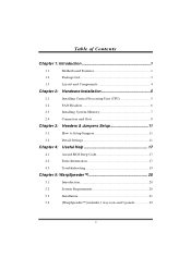
Table of Contents Chapter 1: Introduction 1 1.1 Motherboard Features 1 1.2 Package List 3 1.3 Layout and Components 4 Chapter 2: Hardware Installation 5 2.1 Installing Central Processing Unit (CPU 5 2.2 FAN Headers 6 2.3 Installing System Memory 7 2.4 Connectors and Slots 8 Chapter 3: Headers & Jumpers Setup 11 3.1 How to Setup Jumpers 11 3.2 Detail Settings 11 Chapter 4: Useful Help 17 4.1 Award BIOS Beep Code 17 4.2 Extra Information 17 4.3 Troubleshooting 19 Chapter 5: WarpSpeeder 20 5.1 Introduction 20 5.2 System Requirement 20 5.3 ...
Table of Contents Chapter 1: Introduction 1 1.1 Motherboard Features 1 1.2 Package List 3 1.3 Layout and Components 4 Chapter 2: Hardware Installation 5 2.1 Installing Central Processing Unit (CPU 5 2.2 FAN Headers 6 2.3 Installing System Memory 7 2.4 Connectors and Slots 8 Chapter 3: Headers & Jumpers Setup 11 3.1 How to Setup Jumpers 11 3.2 Detail Settings 11 Chapter 4: Useful Help 17 4.1 Award BIOS Beep Code 17 4.2 Extra Information 17 4.3 Troubleshooting 19 Chapter 5: WarpSpeeder 20 5.1 Introduction 20 5.2 System Requirement 20 5.3 ...
Setup Manual
Page 3
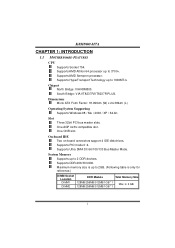
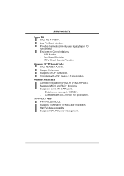
...Memory Supports up to 3700+. Supports DDR-266/333/400. Supports AMD Athlon 64 processor up to 1600MT/s. Chi pset North Bridge: VIA K8M800. Maximum memory size is 2 GB. 1 One CNR slot. Supports HyperTransport Technology up to 2GB. (Following table is only for reference...256MB/512MB/1GB *1 Total Memory Size Max is up to 2 DDR devices. One AGP 4x/8x compatible slot. South Bridge: VIA VT8237R/VT8237R PLUS. K8M800-M7A CHAPTER 1: INTRODUCTION 1.1 MOTHERBOARD FEATURES C PU Supports Socket 754. Dimensions Micro ATX Form Factor: 18.999cm (W) x 24.384cm (L) O perating System...
...Memory Supports up to 3700+. Supports DDR-266/333/400. Supports AMD Athlon 64 processor up to 1600MT/s. Chi pset North Bridge: VIA K8M800. Maximum memory size is 2 GB. 1 One CNR slot. Supports HyperTransport Technology up to 2GB. (Following table is only for reference...256MB/512MB/1GB *1 Total Memory Size Max is up to 2 DDR devices. One AGP 4x/8x compatible slot. South Bridge: VIA VT8237R/VT8237R PLUS. K8M800-M7A CHAPTER 1: INTRODUCTION 1.1 MOTHERBOARD FEATURES C PU Supports Socket 754. Dimensions Micro ATX Form Factor: 18.999cm (W) x 24.384cm (L) O perating System...
Setup Manual
Page 4
... LAN PHY PHY: RTL8201BL/CL. Data transfer rates up to 150 MB/s. - Supports RAID 0 and RAID 1 functions. Compliant with AC'97 Version 2.3 specification. Support 6 channels. K8M800-M7A Supe r I /O fu n ctio n ali ty. Supports ACPI, PCI power management. 2 Half/Full duplex capability. Low Pin Count Interface.
... LAN PHY PHY: RTL8201BL/CL. Data transfer rates up to 150 MB/s. - Supports RAID 0 and RAID 1 functions. Compliant with AC'97 Version 2.3 specification. Support 6 channels. K8M800-M7A Supe r I /O fu n ctio n ali ty. Supports ACPI, PCI power management. 2 Half/Full duplex capability. Low Pin Count Interface.
Setup Manual
Page 5
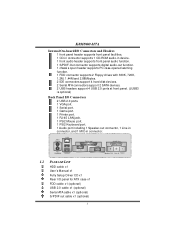
.... 1 Printer port. 1 RJ-45 LAN jack. 1 PS/2 Mouse port. 1 PS/2 Keyboard port. 1 Audio port including 1 Speaker-out connector, 1 Line-in connector, and 1 MIC-in connector. K8M800-M7A Inte rnal On-board I/O Conne ctors and Heade rs 1 front panel header supports front panel facilities. 1 CD-in connector supports 1 CD-ROM audio-in...
.... 1 Printer port. 1 RJ-45 LAN jack. 1 PS/2 Mouse port. 1 PS/2 Keyboard port. 1 Audio port including 1 Speaker-out connector, 1 Line-in connector, and 1 MIC-in connector. K8M800-M7A Inte rnal On-board I/O Conne ctors and Heade rs 1 front panel header supports front panel facilities. 1 CD-in connector supports 1 CD-ROM audio-in...

Setup Manual
Page 6
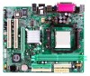
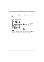
K8M800-M7A 1.3 LAYOUT AND COMPONENTS JKBMS1 JUSBV1 JUSBLAN1 CPU1 JAT XPWR1 DIMM1 DIMM2 FD D1 S ocket 754 JCOM1 JPRNT1 JV GA1 ID E1 ID E2 JAUD_GAM E JGame Port JATXPWR2 JCFAN1 K8 M800 JAUDIO2 LAN PHY AGP1 Super I/O BIO S PCI1 JSPDIF_OUT1 PCI2 BAT1 VT8237R/ VT8237 R PLUS JCM OS1 JS ATA2 JCDI N1 J CI 1 Codec CNR1 PCI3 JSFAN1 JUSB V2 JUSB1 JUSB2 JUSB3(optional ) JS ATA1 JPANEL1 Note: ■ represents the 1st pin. 4
K8M800-M7A 1.3 LAYOUT AND COMPONENTS JKBMS1 JUSBV1 JUSBLAN1 CPU1 JAT XPWR1 DIMM1 DIMM2 FD D1 S ocket 754 JCOM1 JPRNT1 JV GA1 ID E1 ID E2 JAUD_GAM E JGame Port JATXPWR2 JCFAN1 K8 M800 JAUDIO2 LAN PHY AGP1 Super I/O BIO S PCI1 JSPDIF_OUT1 PCI2 BAT1 VT8237R/ VT8237 R PLUS JCM OS1 JS ATA2 JCDI N1 J CI 1 Codec CNR1 PCI3 JSFAN1 JUSB V2 JUSB1 JUSB2 JUSB3(optional ) JS ATA1 JPANEL1 Note: ■ represents the 1st pin. 4
Setup Manual
Page 7
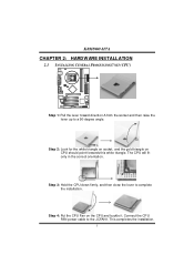
... close the lever to the JCFAN1. The CPU will fit only in the correct orientation. Connect the CPU FAN power cable to complete the installation. K8M800-M7A CHAPTER 2: HARDWARE INSTALLATION 2.1 INSTALLING CENTRAL PROCESSING UNIT (CPU) Step 1: Pull the lever toward direction A from the socket and then raise the lever up to...
... close the lever to the JCFAN1. The CPU will fit only in the correct orientation. Connect the CPU FAN power cable to complete the installation. K8M800-M7A CHAPTER 2: HARDWARE INSTALLATION 2.1 INSTALLING CENTRAL PROCESSING UNIT (CPU) Step 1: Pull the lever toward direction A from the socket and then raise the lever up to...
Setup Manual
Page 8
...: System Fan He ader 1 3 Pin Assignment 1 Ground JCFAN1 2 +12V 3 FAN RPM rate sense 13 JSFA N1 Note: The JCFAN1 and JSFAN1 s upport 3-pin head c onnector. K8M800-M7A 2.2 FAN HEADERS These fan headers support cooling-fans built in the computer. The fan cable and connector may be c onnected to GND. 6 When c onnecti...
...: System Fan He ader 1 3 Pin Assignment 1 Ground JCFAN1 2 +12V 3 FAN RPM rate sense 13 JSFA N1 Note: The JCFAN1 and JSFAN1 s upport 3-pin head c onnector. K8M800-M7A 2.2 FAN HEADERS These fan headers support cooling-fans built in the computer. The fan cable and connector may be c onnected to GND. 6 When c onnecti...

Setup Manual
Page 9
Unlock a DIMM slot by pressing the retaining clips outward. DIMM1 DIMM2 K8M800-M7A 2.3 INSTALLING SYSTEM MEMORY 1. Insert the DIMM vertically and firmly into the slot until the retaining chip snap back in place and the DIMM is properly seated. 7 Align a DIMM on the slot such that the notch on the DIMM matches the break on the Slot. 2.
Unlock a DIMM slot by pressing the retaining clips outward. DIMM1 DIMM2 K8M800-M7A 2.3 INSTALLING SYSTEM MEMORY 1. Insert the DIMM vertically and firmly into the slot until the retaining chip snap back in place and the DIMM is properly seated. 7 Align a DIMM on the slot such that the notch on the DIMM matches the break on the Slot. 2.
Setup Manual
Page 10
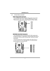
The IDE connectors can connect a master and a slave drive, so you can connect up to IDE1. 40 39 2 1 IDE1 IDE2 8 K8M800-M7A 2.4 CONNECTORS AND SLOTS FDD1: Floppy Disk Connector T he first hard drive should always be connected to four hard disk drives. T he motherboard provides a standard ...
The IDE connectors can connect a master and a slave drive, so you can connect up to IDE1. 40 39 2 1 IDE1 IDE2 8 K8M800-M7A 2.4 CONNECTORS AND SLOTS FDD1: Floppy Disk Connector T he first hard drive should always be connected to four hard disk drives. T he motherboard provides a standard ...
Setup Manual
Page 11
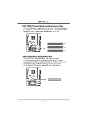
K8M800-M7A PCI1~PCI3: Peripheral Component Interconnect Slots This motherboard is equipped with 3D graphics. 9 PCI stands for improved video efficiency and performance, especially with 3 standard ...
K8M800-M7A PCI1~PCI3: Peripheral Component Interconnect Slots This motherboard is equipped with 3D graphics. 9 PCI stands for improved video efficiency and performance, especially with 3 standard ...

Setup Manual
Page 12
K8M800-M7A CNR1: Communication Network Riser Slot The CNR specification is an open Industry Standard Architecture, and it defines a hardware scalable riser card interface, which supports modem only. 10
K8M800-M7A CNR1: Communication Network Riser Slot The CNR specification is an open Industry Standard Architecture, and it defines a hardware scalable riser card interface, which supports modem only. 10
Setup Manual
Page 13
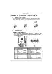
... Ground N/A Power LED (+) Power LED (+) Power LED (-) Power button Ground Key Key Ground IRRX 11 Functio n Sleep button N/A Power LED Power-on button IrDA Connector K8M800-M7A CHAPTER 3: HEADERS & JUMPERS SETUP 3.1 HOW TO SETUP JUMPERS The illustration shows how to connect the PC case's front panel switch f unctions.
... Ground N/A Power LED (+) Power LED (+) Power LED (-) Power button Ground Key Key Ground IRRX 11 Functio n Sleep button N/A Power LED Power-on button IrDA Connector K8M800-M7A CHAPTER 3: HEADERS & JUMPERS SETUP 3.1 HOW TO SETUP JUMPERS The illustration shows how to connect the PC case's front panel switch f unctions.
Setup Manual
Page 14
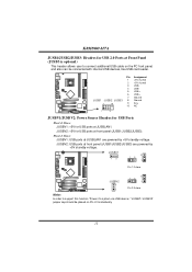
... BV1 13 3 1 3 1 Pin 1-2 close JUSBV 2 3 1 3 1 3 1 Pin 2-3 close Note: In order to connect additional USB cable on Pin 2-3 indi viduall y. 12 JUSBV2: USB ports at JUSBLAN1. K8M800-M7A JUSB1/JUSB2/JUSB3: He ade rs for USB 2.0 Ports at Front Panel (JUSB3 is optional) This header allows user to s upport this function "Power...
... BV1 13 3 1 3 1 Pin 1-2 close JUSBV 2 3 1 3 1 3 1 Pin 2-3 close Note: In order to connect additional USB cable on Pin 2-3 indi viduall y. 12 JUSBV2: USB ports at JUSBLAN1. K8M800-M7A JUSB1/JUSB2/JUSB3: He ade rs for USB 2.0 Ports at Front Panel (JUSB3 is optional) This header allows user to s upport this function "Power...

Setup Manual
Page 15
Pin Assignment 4 3 1 +12V 2 1 2 +12V 3 Ground 4 Ground 13 Pin Assignment 1 +3.3V 2 +3.3V 3 Ground 4 +5V 10 20 5 Ground 6 +5V 7 Ground 8 PW_OK 9 S tandby V ol tage +5V 10 +12V 11 +3.3V 12 -12V 13 Ground 1 11 14 PS_ON 15 Ground 16 Ground 17 Ground 18 -5V 19 +5V 20 +5V JATXPWR2: ATX Powe r Source C onne ctor By connecting this connector, it will provide +12V to connect 20-pin power connector on the ATX power supply. K8M800-M7A JATXPWR1: ATX Powe r Source C onne ctor This connector allows user to CPU power circuit.
Pin Assignment 4 3 1 +12V 2 1 2 +12V 3 Ground 4 Ground 13 Pin Assignment 1 +3.3V 2 +3.3V 3 Ground 4 +5V 10 20 5 Ground 6 +5V 7 Ground 8 PW_OK 9 S tandby V ol tage +5V 10 +12V 11 +3.3V 12 -12V 13 Ground 1 11 14 PS_ON 15 Ground 16 Ground 17 Ground 18 -5V 19 +5V 20 +5V JATXPWR2: ATX Powe r Source C onne ctor By connecting this connector, it will provide +12V to connect 20-pin power connector on the ATX power supply. K8M800-M7A JATXPWR1: ATX Powe r Source C onne ctor This connector allows user to CPU power circuit.

Setup Manual
Page 16
.../ Rear speaker Left JCDIN1: CD-RO M Audio-in Connector This connector allows user to connect the front audio output cable with the PC f ront panel. K8M800-M7A JFAUDIO1: Front Panel Audio Heade r This header allows user to connect the audio source f rom the v ariaty dev ices, like CD-ROM, DVD-ROM...
.../ Rear speaker Left JCDIN1: CD-RO M Audio-in Connector This connector allows user to connect the front audio output cable with the PC f ront panel. K8M800-M7A JFAUDIO1: Front Panel Audio Heade r This header allows user to connect the audio source f rom the v ariaty dev ices, like CD-ROM, DVD-ROM...
Setup Manual
Page 17
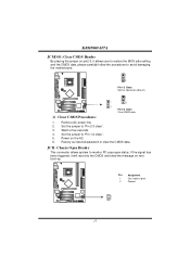
... jumper to avoid damaging the motherboard. 1 3 Pin 1-2 Close: Normal Operation (default). 1 1 3 3 Pin 2-3 Close: Clear CMOS data. ※ Clear CMOS Proce dures: 1. Power on the AC. 6. K8M800-M7A JCMO S1: Cle ar CMOS Heade r By placing the jumper on pin2-3, it will record to "Pin 2-3 close ". 5. Remov e AC power line. 2. JCI1: Chassis...
... jumper to avoid damaging the motherboard. 1 3 Pin 1-2 Close: Normal Operation (default). 1 1 3 3 Pin 2-3 Close: Clear CMOS data. ※ Clear CMOS Proce dures: 1. Power on the AC. 6. K8M800-M7A JCMO S1: Cle ar CMOS Heade r By placing the jumper on pin2-3, it will record to "Pin 2-3 close ". 5. Remov e AC power line. 2. JCI1: Chassis...
Setup Manual
Page 18
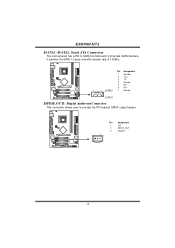
K8M800-M7A JSATA1~JSATA2: Se rial ATA Connectors The motherboard has a PCI to SATA Controller with 2 channels SATA interf ace, it satisfies the SATA 1.0 spec and with transfer rate of 1.5GB/s. 741 Pin Assignment 1 Ground 2 TX+ 3 TX4 Ground 5 RX6 RX+ 7 Ground JS ATA1 JSPDIF_O UT1: Digital Audio-out Conne ctor This connector allows user to connect the PCI bracket SPDIF output header. 1 3 Pin Assignment 1 +5V 2 SPDIF_OUT 3 Ground 16
K8M800-M7A JSATA1~JSATA2: Se rial ATA Connectors The motherboard has a PCI to SATA Controller with 2 channels SATA interf ace, it satisfies the SATA 1.0 spec and with transfer rate of 1.5GB/s. 741 Pin Assignment 1 Ground 2 TX+ 3 TX4 Ground 5 RX6 RX+ 7 Ground JS ATA1 JSPDIF_O UT1: Digital Audio-out Conne ctor This connector allows user to connect the PCI bracket SPDIF output header. 1 3 Pin Assignment 1 +5V 2 SPDIF_OUT 3 Ground 16
Setup Manual
Page 19
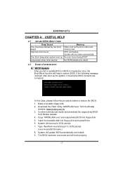
... bootable disk into floppy disk. 5. In this Case, please follow the procedure below to DOS prompt. 7. Download the Flash Utility "AWDFLASH.exe" from Biostar website. 4. If the following message is invaded by two short beeps Meaning Video card not found or v ideo card memory bad High-low siren sound...or BIOS is shown after boot-up No error found during POST Long beeps every other second No DRAM detected or install 4.2 EXTRA INFORMATION A. K8M800-M7A CHAPTER 4: USEFUL HELP 4.1 AWARD BIOS BEEP CODE Beep Sound One long beep followed by virus, the Boot-Block function will help to...
... bootable disk into floppy disk. 5. In this Case, please follow the procedure below to DOS prompt. 7. Download the Flash Utility "AWDFLASH.exe" from Biostar website. 4. If the following message is invaded by two short beeps Meaning Video card not found or v ideo card memory bad High-low siren sound...or BIOS is shown after boot-up No error found during POST Long beeps every other second No DRAM detected or install 4.2 EXTRA INFORMATION A. K8M800-M7A CHAPTER 4: USEFUL HELP 4.1 AWARD BIOS BEEP CODE Beep Sound One long beep followed by virus, the Boot-Block function will help to...
Setup Manual
Page 20
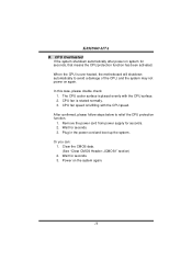
... is rotated normally. 3. Remove the power cord from power supply for seconds. 3. Clear the CMOS data. (See "Close CMOS Header: JCMOS1" section) 2. Power on again. K8M800-M7A B. Plug in the power cord and boot up the system. CPU Overheated If the system shutdown automatically after power on system for seconds. 3. Wait...
... is rotated normally. 3. Remove the power cord from power supply for seconds. 3. Clear the CMOS data. (See "Close CMOS Header: JCMOS1" section) 2. Power on again. K8M800-M7A B. Plug in the power cord and boot up the system. CPU Overheated If the system shutdown automatically after power on system for seconds. 3. Wait...