Setup Manual
Page 1
... here without obligation to notify any purpose. The content of this user's manual is not allowed without notice and we will not occur in writing. i K8M800-M7A FCC Information and Copyright This equipment has been tes ted and found in this publication, in part or in whole, is subject to radio communications...
... here without obligation to notify any purpose. The content of this user's manual is not allowed without notice and we will not occur in writing. i K8M800-M7A FCC Information and Copyright This equipment has been tes ted and found in this publication, in part or in whole, is subject to radio communications...
Setup Manual
Page 3
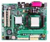
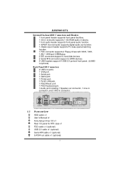
... Technology up to 1600MT/s. One CNR slot. System Memory Supports up to 2 DDR devices. Supports DDR-266/333/400. Chi pset North Bridge: VIA K8M800. On-board IDE Two on-board connectors support 4 IDE disk drives. Sl ot Three 32bit PCI bus master slots. Supports PIO mode 0~4. South Bridge:...GB. 1 Supports AMD Sempron processo r. Dimensions Micro ATX Form Factor: 18.999cm (W) x 24.384cm (L) O perating System Supporting Supports Windows 98 / Me / 2000 / XP / 64-bit. K8M800-M7A CHAPTER 1: INTRODUCTION 1.1 MOTHERBOARD FEATURES C PU Supports Socket 754.
... Technology up to 1600MT/s. One CNR slot. System Memory Supports up to 2 DDR devices. Supports DDR-266/333/400. Chi pset North Bridge: VIA K8M800. On-board IDE Two on-board connectors support 4 IDE disk drives. Sl ot Three 32bit PCI bus master slots. Supports PIO mode 0~4. South Bridge:...GB. 1 Supports AMD Sempron processo r. Dimensions Micro ATX Form Factor: 18.999cm (W) x 24.384cm (L) O perating System Supporting Supports Windows 98 / Me / 2000 / XP / 64-bit. K8M800-M7A CHAPTER 1: INTRODUCTION 1.1 MOTHERBOARD FEATURES C PU Supports Socket 754.
Setup Manual
Page 4
.... Supports 2 serial ATA (SATA) ports. - Supports ACPI, PCI power management. 2 Data transfer rates up to 150 MB/s. - Supports 10 Mb/s and 100 Mb/s auto-negotiation. K8M800-M7A Supe r I /O fu n ctio n ali ty. Provides the most commonly used legacy Super I /O Chip: ITE IT8705AF.
.... Supports 2 serial ATA (SATA) ports. - Supports ACPI, PCI power management. 2 Data transfer rates up to 150 MB/s. - Supports 10 Mb/s and 100 Mb/s auto-negotiation. K8M800-M7A Supe r I /O fu n ctio n ali ty. Provides the most commonly used legacy Super I /O Chip: ITE IT8705AF.
Setup Manual
Page 5
K8M800-M7A Inte rnal On-board I/O Conne ctors and Heade rs 1 front panel header supports front panel facilities. 1 CD-in connector supports 1 CD-ROM audio-in device. 1 ...
K8M800-M7A Inte rnal On-board I/O Conne ctors and Heade rs 1 front panel header supports front panel facilities. 1 CD-in connector supports 1 CD-ROM audio-in device. 1 ...

Setup Manual
Page 6
K8M800-M7A 1.3 LAYOUT AND COMPONENTS JKBMS1 JUSBV1 JUSBLAN1 CPU1 JAT XPWR1 DIMM1 DIMM2 FD D1 S ocket 754 JCOM1 JPRNT1 JV GA1 ID E1 ID E2 JAUD_GAM E JGame Port JATXPWR2 JCFAN1 K8 M800 JAUDIO2 LAN PHY AGP1 Super I/O BIO S PCI1 JSPDIF_OUT1 PCI2 BAT1 VT8237R/ VT8237 R PLUS JCM OS1 JS ATA2 JCDI N1 J CI 1 Codec CNR1 PCI3 JSFAN1 JUSB V2 JUSB1 JUSB2 JUSB3(optional ) JS ATA1 JPANEL1 Note: ■ represents the 1st pin. 4
K8M800-M7A 1.3 LAYOUT AND COMPONENTS JKBMS1 JUSBV1 JUSBLAN1 CPU1 JAT XPWR1 DIMM1 DIMM2 FD D1 S ocket 754 JCOM1 JPRNT1 JV GA1 ID E1 ID E2 JAUD_GAM E JGame Port JATXPWR2 JCFAN1 K8 M800 JAUDIO2 LAN PHY AGP1 Super I/O BIO S PCI1 JSPDIF_OUT1 PCI2 BAT1 VT8237R/ VT8237 R PLUS JCM OS1 JS ATA2 JCDI N1 J CI 1 Codec CNR1 PCI3 JSFAN1 JUSB V2 JUSB1 JUSB2 JUSB3(optional ) JS ATA1 JPANEL1 Note: ■ represents the 1st pin. 4
Setup Manual
Page 7
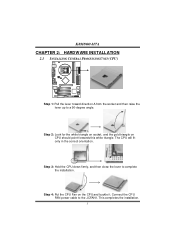
... the installation. Step 3: Hold the CPU down firmly, and then close the lever to the JCFAN1. The CPU will fit only in the correct orientation. K8M800-M7A CHAPTER 2: HARDWARE INSTALLATION 2.1 INSTALLING CENTRAL PROCESSING UNIT (CPU) Step 1: Pull the lever toward direction A from the socket and then raise the lever up to a 90...
... the installation. Step 3: Hold the CPU down firmly, and then close the lever to the JCFAN1. The CPU will fit only in the correct orientation. K8M800-M7A CHAPTER 2: HARDWARE INSTALLATION 2.1 INSTALLING CENTRAL PROCESSING UNIT (CPU) Step 1: Pull the lever toward direction A from the socket and then raise the lever up to a 90...
Setup Manual
Page 8
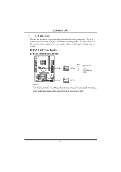
... RPM rate sense 13 JSFA N1 Note: The JCFAN1 and JSFAN1 s upport 3-pin head c onnector. The fan cable and connector may be c onnected to pin#1. K8M800-M7A 2.2 FAN HEADERS These fan headers support cooling-fans built in the computer.
... RPM rate sense 13 JSFA N1 Note: The JCFAN1 and JSFAN1 s upport 3-pin head c onnector. The fan cable and connector may be c onnected to pin#1. K8M800-M7A 2.2 FAN HEADERS These fan headers support cooling-fans built in the computer.

Setup Manual
Page 9
Insert the DIMM vertically and firmly into the slot until the retaining chip snap back in place and the DIMM is properly seated. 7 Unlock a DIMM slot by pressing the retaining clips outward. Align a DIMM on the slot such that the notch on the DIMM matches the break on the Slot. 2. DIMM1 DIMM2 K8M800-M7A 2.3 INSTALLING SYSTEM MEMORY 1.
Insert the DIMM vertically and firmly into the slot until the retaining chip snap back in place and the DIMM is properly seated. 7 Unlock a DIMM slot by pressing the retaining clips outward. Align a DIMM on the slot such that the notch on the DIMM matches the break on the Slot. 2. DIMM1 DIMM2 K8M800-M7A 2.3 INSTALLING SYSTEM MEMORY 1.
Setup Manual
Page 10
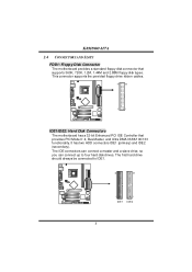
... 2 1 IDE1/IDE2: Hard Disk Connectors The motherboard has a 32-bit Enhanced PCI IDE Controller that supports 360K, 720K, 1.2M, 1.44M and 2.88M floppy disk types. K8M800-M7A 2.4 CONNECTORS AND SLOTS FDD1: Floppy Disk Connector T he first hard drive should always be connected to four hard disk drives. The IDE connectors can connect...
... 2 1 IDE1/IDE2: Hard Disk Connectors The motherboard has a 32-bit Enhanced PCI IDE Controller that supports 360K, 720K, 1.2M, 1.44M and 2.88M floppy disk types. K8M800-M7A 2.4 CONNECTORS AND SLOTS FDD1: Floppy Disk Connector T he first hard drive should always be connected to four hard disk drives. The IDE connectors can connect...
Setup Manual
Page 11
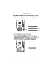
... video cards for PCI slots, but it is equipped with 3D graphics. 9 PCI stands for Peripheral Component Interconnect, and it is designated as 32 bits. K8M800-M7A PCI1~PCI3: Peripheral Component Interconnect Slots This motherboard is a bus standard for expansion cards.
... video cards for PCI slots, but it is equipped with 3D graphics. 9 PCI stands for Peripheral Component Interconnect, and it is designated as 32 bits. K8M800-M7A PCI1~PCI3: Peripheral Component Interconnect Slots This motherboard is a bus standard for expansion cards.

Setup Manual
Page 12
K8M800-M7A CNR1: Communication Network Riser Slot The CNR specification is an open Industry Standard Architecture, and it defines a hardware scalable riser card interface, which supports modem only. 10
K8M800-M7A CNR1: Communication Network Riser Slot The CNR specification is an open Industry Standard Architecture, and it defines a hardware scalable riser card interface, which supports modem only. 10
Setup Manual
Page 13
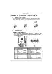
... Ground N/A Power LED (+) Power LED (+) Power LED (-) Power button Ground Key Key Ground IRRX 11 Functio n Sleep button N/A Power LED Power-on button IrDA Connector K8M800-M7A CHAPTER 3: HEADERS & JUMPERS SETUP 3.1 HOW TO SETUP JUMPERS The illustration shows how to connect the PC case's front panel switch f unctions.
... Ground N/A Power LED (+) Power LED (+) Power LED (-) Power button Ground Key Key Ground IRRX 11 Functio n Sleep button N/A Power LED Power-on button IrDA Connector K8M800-M7A CHAPTER 3: HEADERS & JUMPERS SETUP 3.1 HOW TO SETUP JUMPERS The illustration shows how to connect the PC case's front panel switch f unctions.
Setup Manual
Page 14
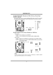
..., like USB card reader. JUS BV1 13 3 1 3 1 Pin 1-2 close JUSBV 2 3 1 3 1 3 1 Pin 2-3 close Note: In order to connect additional USB cable on Pin 2-3 indi viduall y. 12 K8M800-M7A JUSB1/JUSB2/JUSB3: He ade rs for USB 2.0 Ports at front panel (JUSB1/JUSB2/JUSB3) are powered by +5V standby voltage. JUSBV2: +5V for USB...
..., like USB card reader. JUS BV1 13 3 1 3 1 Pin 1-2 close JUSBV 2 3 1 3 1 3 1 Pin 2-3 close Note: In order to connect additional USB cable on Pin 2-3 indi viduall y. 12 K8M800-M7A JUSB1/JUSB2/JUSB3: He ade rs for USB 2.0 Ports at front panel (JUSB1/JUSB2/JUSB3) are powered by +5V standby voltage. JUSBV2: +5V for USB...

Setup Manual
Page 15
K8M800-M7A JATXPWR1: ATX Powe r Source C onne ctor This connector allows user to CPU power circuit. Pin Assignment 4 3 1 +12V 2 1 2 +12V 3 Ground 4 Ground 13 Pin Assignment 1 +3.3V 2 +3.3V 3 Ground 4 +5V 10 20 5 Ground 6 +5V 7 Ground 8 PW_OK 9 S tandby V ol tage +5V 10 +12V 11 +3.3V 12 -12V 13 Ground 1 11 14 PS_ON 15 Ground 16 Ground 17 Ground 18 -5V 19 +5V 20 +5V JATXPWR2: ATX Powe r Source C onne ctor By connecting this connector, it will provide +12V to connect 20-pin power connector on the ATX power supply.
K8M800-M7A JATXPWR1: ATX Powe r Source C onne ctor This connector allows user to CPU power circuit. Pin Assignment 4 3 1 +12V 2 1 2 +12V 3 Ground 4 Ground 13 Pin Assignment 1 +3.3V 2 +3.3V 3 Ground 4 +5V 10 20 5 Ground 6 +5V 7 Ground 8 PW_OK 9 S tandby V ol tage +5V 10 +12V 11 +3.3V 12 -12V 13 Ground 1 11 14 PS_ON 15 Ground 16 Ground 17 Ground 18 -5V 19 +5V 20 +5V JATXPWR2: ATX Powe r Source C onne ctor By connecting this connector, it will provide +12V to connect 20-pin power connector on the ATX power supply.

Setup Manual
Page 16
... connector allows user to connect the front audio output cable with the PC f ront panel. It will disable the output on back panel audio connectors. K8M800-M7A JFAUDIO1: Front Panel Audio Heade r This header allows user to connect the audio source f rom the v ariaty dev ices, like CD-ROM, DVD-ROM, PCI...
... connector allows user to connect the front audio output cable with the PC f ront panel. It will disable the output on back panel audio connectors. K8M800-M7A JFAUDIO1: Front Panel Audio Heade r This header allows user to connect the audio source f rom the v ariaty dev ices, like CD-ROM, DVD-ROM, PCI...
Setup Manual
Page 17
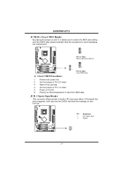
... Heade r This connector allows system to avoid damaging the motherboard. 1 3 Pin 1-2 Close: Normal Operation (default). 1 1 3 3 Pin 2-3 Close: Clear CMOS data. ※ Clear CMOS Proce dures: 1. K8M800-M7A JCMO S1: Cle ar CMOS Heade r By placing the jumper on pin2-3, it will record to "Pin 2-3 close ". 5. Remov e AC power line. 2. Set the jumper...
... Heade r This connector allows system to avoid damaging the motherboard. 1 3 Pin 1-2 Close: Normal Operation (default). 1 1 3 3 Pin 2-3 Close: Clear CMOS data. ※ Clear CMOS Proce dures: 1. K8M800-M7A JCMO S1: Cle ar CMOS Heade r By placing the jumper on pin2-3, it will record to "Pin 2-3 close ". 5. Remov e AC power line. 2. Set the jumper...
Setup Manual
Page 18
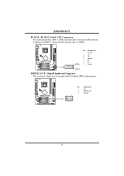
K8M800-M7A JSATA1~JSATA2: Se rial ATA Connectors The motherboard has a PCI to SATA Controller with 2 channels SATA interf ace, it satisfies the SATA 1.0 spec and with transfer rate of 1.5GB/s. 741 Pin Assignment 1 Ground 2 TX+ 3 TX4 Ground 5 RX6 RX+ 7 Ground JS ATA1 JSPDIF_O UT1: Digital Audio-out Conne ctor This connector allows user to connect the PCI bracket SPDIF output header. 1 3 Pin Assignment 1 +5V 2 SPDIF_OUT 3 Ground 16
K8M800-M7A JSATA1~JSATA2: Se rial ATA Connectors The motherboard has a PCI to SATA Controller with 2 channels SATA interf ace, it satisfies the SATA 1.0 spec and with transfer rate of 1.5GB/s. 741 Pin Assignment 1 Ground 2 TX+ 3 TX4 Ground 5 RX6 RX+ 7 Ground JS ATA1 JSPDIF_O UT1: Digital Audio-out Conne ctor This connector allows user to connect the PCI bracket SPDIF output header. 1 3 Pin Assignment 1 +5V 2 SPDIF_OUT 3 Ground 16
Setup Manual
Page 19
... respectively BIOS into floppy drive and press Enter. 6. Download the Flash Utility "AWDFLASH.exe" from Biostar website. 4. Confirm motherboard model and download the respectively BIOS from the Biostar website: www.biostar.com.tw 3. System will work properly. 17 The BIOS has been recovered and will update BIOS ...overheated System will shut down automatically One Short beep when system boot-up the system, it means the BIOS contents are corrupted. K8M800-M7A CHAPTER 4: USEFUL HELP 4.1 AWARD BIOS BEEP CODE Beep Sound One long beep followed by virus, the Boot-Block function will help ...
... respectively BIOS into floppy drive and press Enter. 6. Download the Flash Utility "AWDFLASH.exe" from Biostar website. 4. Confirm motherboard model and download the respectively BIOS from the Biostar website: www.biostar.com.tw 3. System will work properly. 17 The BIOS has been recovered and will update BIOS ...overheated System will shut down automatically One Short beep when system boot-up the system, it means the BIOS contents are corrupted. K8M800-M7A CHAPTER 4: USEFUL HELP 4.1 AWARD BIOS BEEP CODE Beep Sound One long beep followed by virus, the Boot-Block function will help ...
Setup Manual
Page 20
... CMOS data. (See "Close CMOS Header: JCMOS1" section) 2. CPU fan speed is over heated, the motherboard will shutdown automatically to relief the CPU protection function. 1. K8M800-M7A B. The CPU cooler surface is rotated normally. 3. Wait for seconds, that means the CPU protection function has been activated. Power on again. CPU Overheated If...
... CMOS data. (See "Close CMOS Header: JCMOS1" section) 2. CPU fan speed is over heated, the motherboard will shutdown automatically to relief the CPU protection function. 1. K8M800-M7A B. The CPU cooler surface is rotated normally. 3. Wait for seconds, that means the CPU protection function has been activated. Power on again. CPU Overheated If...
Setup Manual
Page 21
... data using backup disks. Indicator light on key board does not turn 2. Back up the hard drive is extremely important. Set master/slave jumpers correctly. 2. K8M800-M7A 4.3 TROUBLESHOOTING Probable Solution 1. Make sure power cable is in ; on . System inoperativ e. Check cable running from hard disk 1. Backing up data and applications f iles. Hard...
... data using backup disks. Indicator light on key board does not turn 2. Back up the hard drive is extremely important. Set master/slave jumpers correctly. 2. K8M800-M7A 4.3 TROUBLESHOOTING Probable Solution 1. Make sure power cable is in ; on . System inoperativ e. Check cable running from hard disk 1. Backing up data and applications f iles. Hard...