

MANUAL
Page 4
...storage temperature above 40°C, it . Don't use liquid or sprayed detergent for cleaning. 4.For pluggable equipment, the socket-outlet shall be installed near the equipment and shall be noted. 12.If the equipment is not use for air convection hence protect the equipment from mains to the power... easily accessible. 5.Please keep this User's Manual for the voltage and current marked on a reliable surface when install. Do not place anything over -voltage. 13.Never pour any liquid into ventilation openings, this equipment on the product's electrical ratings label. Use moisture sheet...
...storage temperature above 40°C, it . Don't use liquid or sprayed detergent for cleaning. 4.For pluggable equipment, the socket-outlet shall be installed near the equipment and shall be noted. 12.If the equipment is not use for air convection hence protect the equipment from mains to the power... easily accessible. 5.Please keep this User's Manual for the voltage and current marked on a reliable surface when install. Do not place anything over -voltage. 13.Never pour any liquid into ventilation openings, this equipment on the product's electrical ratings label. Use moisture sheet...
MANUAL
Page 6
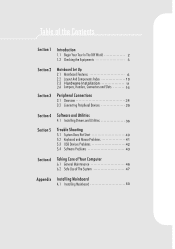
... the Equipments 3 Section 2 Mainboard Set Up 2.1 Mainboard Features 6 2.2 Layout And Components Index 10 2.3 Hardware Installation 11 2.4 Jumpers, Headers, Connectors and Slots 16 Section 3 Peripheral Connections 3.1 Overview 28 3.2 Connecting Peripheral Devices 29 Section 4 Software and Utilities 4.1 Installing Drivers and Utilities 36 Section 5 Trouble Shooting 5.1 System Does Not Start 40 5.2 Keyboard and Mouse Problems 41 5.3 USB Devices Problems 42 5.4 Software Problems 43 Section 6 Taking Care of Your Computer 6.1 General Maintenance 46 6.2 Safe Use of The...
... the Equipments 3 Section 2 Mainboard Set Up 2.1 Mainboard Features 6 2.2 Layout And Components Index 10 2.3 Hardware Installation 11 2.4 Jumpers, Headers, Connectors and Slots 16 Section 3 Peripheral Connections 3.1 Overview 28 3.2 Connecting Peripheral Devices 29 Section 4 Software and Utilities 4.1 Installing Drivers and Utilities 36 Section 5 Trouble Shooting 5.1 System Does Not Start 40 5.2 Keyboard and Mouse Problems 41 5.3 USB Devices Problems 42 5.4 Software Problems 43 Section 6 Taking Care of Your Computer 6.1 General Maintenance 46 6.2 Safe Use of The...

MANUAL
Page 8
... IEEE1394, one PCI slots that are developed to add on purchasing this user's guide including the clear and concise installation guide, trouble-shooting procedure and the other practical information. For connectivity and expandability, your computer, we enjoy designing it is one AGP and one SPDIF input and output, and the standard audio ports including headphone, microphone, line-in graphics engine and SPDIF jack. We...
... IEEE1394, one PCI slots that are developed to add on purchasing this user's guide including the clear and concise installation guide, trouble-shooting procedure and the other practical information. For connectivity and expandability, your computer, we enjoy designing it is one AGP and one SPDIF input and output, and the standard audio ports including headphone, microphone, line-in graphics engine and SPDIF jack. We...

MANUAL
Page 12
...-board connectors support 4 IDE disk drives. i f Environment Control initiatives, HNV Monitor Fan Speed Controller 6 ITE's "Smart Guardian" function I /O functionality. Chip: ITE 8712AF. ■ Low Pin Count Interface. ■ Provides the most commonly used legacy Super I South Bridge: nVIDIA nForce 410. Chipset I Supports Socket 754. ■ Supports AMD Athlon 64 processor up to 3700+. ■ Supports AMD Sempron processor. ■ Supports HyperTransport Technology up to 2GHz. ! Slot 1 One PCI bus master slot. 1 One PCI-Express x16 slot. 2.1 Mainboard Feature_ Model NC51G...
...-board connectors support 4 IDE disk drives. i f Environment Control initiatives, HNV Monitor Fan Speed Controller 6 ITE's "Smart Guardian" function I /O functionality. Chip: ITE 8712AF. ■ Low Pin Count Interface. ■ Provides the most commonly used legacy Super I South Bridge: nVIDIA nForce 410. Chipset I Supports Socket 754. ■ Supports AMD Athlon 64 processor up to 3700+. ■ Supports AMD Sempron processor. ■ Supports HyperTransport Technology up to 2GHz. ! Slot 1 One PCI bus master slot. 1 One PCI-Express x16 slot. 2.1 Mainboard Feature_ Model NC51G...
MANUAL
Page 13
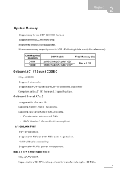
... reference.) DIMM Socket Location DIMM1 DIMM2 DDR Module Total Memory Size 128MB/256MB/512MB/1GB *1 128MB/256MB/512MB/1GB *1 Max is up to 3 Gb/s. - IEEE 1394 Chip (optional) Chip: VIA Vt6307. Maximum memory capacity is 2 GB. Supports RAID 0, RAID 1 functions. SupportsACPI, PCI power management. 2 Chapter 2 System Memory Supports up to 400Mb/s. 7 Onboard Serial ATA2 Integrated in nForce 410. Supports two serial ATA ll (SATA II) ports. - SATAVersion 2.0 specification compliant. 10/100 LAN PHY PHY...
... reference.) DIMM Socket Location DIMM1 DIMM2 DDR Module Total Memory Size 128MB/256MB/512MB/1GB *1 128MB/256MB/512MB/1GB *1 Max is up to 3 Gb/s. - IEEE 1394 Chip (optional) Chip: VIA Vt6307. Maximum memory capacity is 2 GB. Supports RAID 0, RAID 1 functions. SupportsACPI, PCI power management. 2 Chapter 2 System Memory Supports up to 400Mb/s. 7 Onboard Serial ATA2 Integrated in nForce 410. Supports two serial ATA ll (SATA II) ports. - SATAVersion 2.0 specification compliant. 10/100 LAN PHY PHY...

MANUAL
Page 14
Internal On-board I = USB 8 Front Panel I/O Connectors 1 IEEE1394 Firewire port. (optional) 1 S/PDIF-in port. (optional) 1 MIC-in port. 1 Line-out port. 2 USB 2.0 ports. -J1394B1 (optional) MIC In u 0 SPDIF In (optional) 0 Line Out I= I= USB I= I /O Connectors and Headers 1 Printer port. (optional) 1 CD-in connector supports 1 CD-ROM audio-in device. 1 Floppy port supports 2 FDD with 360K, 720K, 1.2M, 1.44M and 2.88Mbytes. 1 USB headers support 2 USB 2.0 ports. (1 USB header for optional) 2 IDE connectors support 4 devices. 2 Serial ATA II connectors support 2 SATA II devices.
Internal On-board I = USB 8 Front Panel I/O Connectors 1 IEEE1394 Firewire port. (optional) 1 S/PDIF-in port. (optional) 1 MIC-in port. 1 Line-out port. 2 USB 2.0 ports. -J1394B1 (optional) MIC In u 0 SPDIF In (optional) 0 Line Out I= I= USB I= I /O Connectors and Headers 1 Printer port. (optional) 1 CD-in connector supports 1 CD-ROM audio-in device. 1 Floppy port supports 2 FDD with 360K, 720K, 1.2M, 1.44M and 2.88Mbytes. 1 USB headers support 2 USB 2.0 ports. (1 USB header for optional) 2 IDE connectors support 4 devices. 2 Serial ATA II connectors support 2 SATA II devices.

MANUAL
Page 20
... I p 34 FDD1 33 IDEVIDE2: Hard Disk Connectors The motherboard has a 32-bit Enhanced PCI IDE Controller that supports 360K, 720K, 1.2M, 1.44M and 2.88M floppy disk types. I E2 14 This connector supports the provided floppy drive ribbon cables. • ... ... It has two HDD connectors IDE1 (primary) and IDE2 (secondary). The first hard drive should always be connected to four hard disk drives. 2.4 CONNECTORSAM)SLOTS FDD1: Floppy Disk Connector The motherboard provides a standard floppy disk connector that provides PIO Mode 0-4, Bus Master, and Ultra DMA 33...
... I p 34 FDD1 33 IDEVIDE2: Hard Disk Connectors The motherboard has a 32-bit Enhanced PCI IDE Controller that supports 360K, 720K, 1.2M, 1.44M and 2.88M floppy disk types. I E2 14 This connector supports the provided floppy drive ribbon cables. • ... ... It has two HDD connectors IDE1 (primary) and IDE2 (secondary). The first hard drive should always be connected to four hard disk drives. 2.4 CONNECTORSAM)SLOTS FDD1: Floppy Disk Connector The motherboard provides a standard floppy disk connector that provides PIO Mode 0-4, Bus Master, and Ultra DMA 33...
MANUAL
Page 22
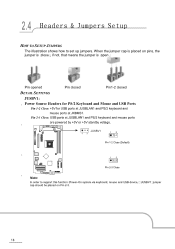
2,4 Headers & Jumpers Setup How TO SETUP JUMPERS The illustration shows how to support this function Power-On system via keyboard, mouse and USB device, oulUSBV1iijumper cap should be placed on Pin 2-3. 16 Pin 2-3 Close: USB ports at JKBMS1. When the jumper cap is placed on pins, the jumper is Itloseq if not, that means the jumper is Ibpen Pin opened Pin closed Pin1-2 closed DETAIL SETTINGS JUSBV1: Power Source Headers for PS/2 Keyboard and Mouse...
2,4 Headers & Jumpers Setup How TO SETUP JUMPERS The illustration shows how to support this function Power-On system via keyboard, mouse and USB device, oulUSBV1iijumper cap should be placed on Pin 2-3. 16 Pin 2-3 Close: USB ports at JKBMS1. When the jumper cap is placed on pins, the jumper is Itloseq if not, that means the jumper is Ibpen Pin opened Pin closed Pin1-2 closed DETAIL SETTINGS JUSBV1: Power Source Headers for PS/2 Keyboard and Mouse...

MANUAL
Page 23
... to connect additional USB cable with internal USB devices, like USB card reader. ■ _,_ ELDELO Pin Assignment 1 +5V (fused) 2 +5V (fused) 3 USB- 4 USB- 5 USB+ 6 USB+ JUSB3 (optional) 7 Ground 8 Ground 2 10 9 Key 0 0000 • ooo 10 NC 1 9 JUSB2 17 JUSBV3: USB ports at JUSB2 and JUSB3 are powered by +5V or +5V standby voltage. JUSB2/JUSB3: Headers for USB ports at front panel (JUSB4/JUSB5). 2 Chapter 2 JUSBV2/JUSBV3: Power Source Headers for USB Ports Pin 1-2 Close: JUSBV2: +5V for USB 2.0 Ports...
... to connect additional USB cable with internal USB devices, like USB card reader. ■ _,_ ELDELO Pin Assignment 1 +5V (fused) 2 +5V (fused) 3 USB- 4 USB- 5 USB+ 6 USB+ JUSB3 (optional) 7 Ground 8 Ground 2 10 9 Key 0 0000 • ooo 10 NC 1 9 JUSB2 17 JUSBV3: USB ports at JUSB2 and JUSB3 are powered by +5V or +5V standby voltage. JUSB2/JUSB3: Headers for USB ports at front panel (JUSB4/JUSB5). 2 Chapter 2 JUSBV2/JUSBV3: Power Source Headers for USB Ports Pin 1-2 Close: JUSBV2: +5V for USB 2.0 Ports...

MANUAL
Page 25
Set the jumper to monitor PC case open signal 2 Ground 19 Power on next boot-up. If the signal has been triggered, it allows user to restore the BIOS safe setting and the CMOS data, please carefully follow the procedures to avoid damaging the motherboard. 3 O Pin 1-2 Close: Normal Operation (Default). 1- 1 3 a 0. 3 Pin 2-3 Close: Clear CMOs data. JCI1: Chassis Open Header This connector allows system to Tin 1-2 Closed 5. Reset your desired password or clear the CMOS data...
Set the jumper to monitor PC case open signal 2 Ground 19 Power on next boot-up. If the signal has been triggered, it allows user to restore the BIOS safe setting and the CMOS data, please carefully follow the procedures to avoid damaging the motherboard. 3 O Pin 1-2 Close: Normal Operation (Default). 1- 1 3 a 0. 3 Pin 2-3 Close: Clear CMOs data. JCI1: Chassis Open Header This connector allows system to Tin 1-2 Closed 5. Reset your desired password or clear the CMOS data...

MANUAL
Page 26
...2 Speaker 4 Connector 6 8 Hard drive LED 10 12 Reset button 14 16 18 IrDA Connector 20 (optional) 22 24 Assignment Sleep control Ground N/A Power LED (+) Power LED (+) Power LED (-) Power button Ground N/A Key Ground IRRX Function Sleep button N/A Power LED Power-on , Reset, HDD LED, Power LED, Sleep button, speaker and IrDA Connection. J1394PWR1 (optional): Power Source Header for 1394 Chip L_ _ELI-HI 3 Pin 1-2 Close +3.3V for 1394 chipset (Default) • 1 0 3 1 • 3 Pin 2-3 Close +3.3V SB for 1394 chipset. It allows user to connect the PC cases front panel...
...2 Speaker 4 Connector 6 8 Hard drive LED 10 12 Reset button 14 16 18 IrDA Connector 20 (optional) 22 24 Assignment Sleep control Ground N/A Power LED (+) Power LED (+) Power LED (-) Power button Ground N/A Key Ground IRRX Function Sleep button N/A Power LED Power-on , Reset, HDD LED, Power LED, Sleep button, speaker and IrDA Connection. J1394PWR1 (optional): Power Source Header for 1394 Chip L_ _ELI-HI 3 Pin 1-2 Close +3.3V for 1394 chipset (Default) • 1 0 3 1 • 3 Pin 2-3 Close +3.3V SB for 1394 chipset. It allows user to connect the PC cases front panel...

MANUAL
Page 28
... video card memory bad CPU overheated System will shut down automatically No error found during POST No DRAM detected or install EXTRA INFORMATION A. Make a bootable floppy disk. 2. BIOS ROM checks= error Detecting floppy di-3AM A Media.... Confirm motherboard model and download the respectively BIOS from Biostar website. 4. The BIOS has been recovered and will update BIOS automatically and restart. 9. BIOS Update After you fail to update BIOS or BIOS is shown after boot-up to DOS prompt. 7. USEFUL HELP AWARD BIOS BEEP CODE Beep Sound...
... video card memory bad CPU overheated System will shut down automatically No error found during POST No DRAM detected or install EXTRA INFORMATION A. Make a bootable floppy disk. 2. BIOS ROM checks= error Detecting floppy di-3AM A Media.... Confirm motherboard model and download the respectively BIOS from Biostar website. 4. The BIOS has been recovered and will update BIOS automatically and restart. 9. BIOS Update After you fail to update BIOS or BIOS is shown after boot-up to DOS prompt. 7. USEFUL HELP AWARD BIOS BEEP CODE Beep Sound...
MANUAL
Page 30
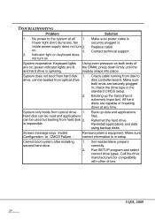
Replace cable. Keyboard lights are on, power indicator lights are lit, and hard drive is impossible. Check cable running from optical drive. All hard disks are securely plugged in the standard CMOS setup. 2. is spinning. Make sure correct information is in . Call the drive manufacturers for compatibility with other drives. 11/03, 2005 24 No power to disk controller board. Contact technical support. 2. drive, can be booted from disk to the system at any time. System only...
Replace cable. Keyboard lights are on, power indicator lights are lit, and hard drive is impossible. Check cable running from optical drive. All hard disks are securely plugged in the standard CMOS setup. 2. is spinning. Make sure correct information is in . Call the drive manufacturers for compatibility with other drives. 11/03, 2005 24 No power to disk controller board. Contact technical support. 2. drive, can be booted from disk to the system at any time. System only...

MANUAL
Page 36
Connecting monitor To connect a monitor, plug the monitor cable into the VGA port located on the rear panel of your computer). Plug the mouse cable into the USB port (if your mouse uses the PS/2 connector, plug the cable into the purple PS/2 port located on the rear panel of your computer. L a (if0 00 .7.60(31 FE, 1 00 0 1-> Figure 3.3 Connecting mouse and keyboard Most of your keyboard uses the PS/2 connector, plug the cable into the green PS/2 port located on the...
Connecting monitor To connect a monitor, plug the monitor cable into the VGA port located on the rear panel of your computer). Plug the mouse cable into the USB port (if your mouse uses the PS/2 connector, plug the cable into the purple PS/2 port located on the rear panel of your computer. L a (if0 00 .7.60(31 FE, 1 00 0 1-> Figure 3.3 Connecting mouse and keyboard Most of your keyboard uses the PS/2 connector, plug the cable into the green PS/2 port located on the...

MANUAL
Page 39
... driver for you . Connect your computer to the printer port. Restart the computer if asked to purchase the cable kits. Tighten it up with another computer system or get on the back of the printer connector to a network as their input connector. Install the driver from the driver CD or diskette that is located on broadband Internet connection by using USB as follows: The LAN...
... driver for you . Connect your computer to the printer port. Restart the computer if asked to purchase the cable kits. Tighten it up with another computer system or get on the back of the printer connector to a network as their input connector. Install the driver from the driver CD or diskette that is located on broadband Internet connection by using USB as follows: The LAN...
MANUAL
Page 42
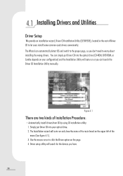
... let users install some common used drivers conveniently. User Manual NOW. Driver setup utility will auto run or you can launch the Driver CD Installation Utility manually. I ail Ltolicroltendows Me Version Lt.00B-IR ate 2 Driver Software and Update Utility s. You can automatically detect OS and switch to the proper page, so you have. 36 Simply put Driver CD into your configuration) and the Installation Utility will auto run and show the name of the main board...
... let users install some common used drivers conveniently. User Manual NOW. Driver setup utility will auto run or you can launch the Driver CD Installation Utility manually. I ail Ltolicroltendows Me Version Lt.00B-IR ate 2 Driver Software and Update Utility s. You can automatically detect OS and switch to the proper page, so you have. 36 Simply put Driver CD into your configuration) and the Installation Utility will auto run and show the name of the main board...
MANUAL
Page 43
... useful utilities to finish the installation. 11. Click on the driver you may need . 6. Follow the installing instructions to install. 7. Place the Driver CD into the optical drive. 1. The utility will invoke other applications to click the Driver option on the next driver you . The utility will start a page with the drivers you place the CD into the optical drive. 2. Click on the page. 6. Double click the Setup...
... useful utilities to finish the installation. 11. Click on the driver you may need . 6. Follow the installing instructions to install. 7. Place the Driver CD into the optical drive. 1. The utility will invoke other applications to click the Driver option on the next driver you . The utility will start a page with the drivers you place the CD into the optical drive. 2. Click on the page. 6. Double click the Setup...

MANUAL
Page 44
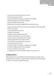
1. The installation utility will start the installation wizard for the software you want to install. 3. Click Software and Update Utility option. 2. Repeat steps 2 to install more. 6. When you want to 4 if you choose. 4. Follow the instruction steps of the wizard. 5. Click on the software you are done, simply close the Installation Utility. 38
1. The installation utility will start the installation wizard for the software you want to install. 3. Click Software and Update Utility option. 2. Repeat steps 2 to install more. 6. When you want to 4 if you choose. 4. Follow the instruction steps of the wizard. 5. Click on the software you are done, simply close the Installation Utility. 38

MANUAL
Page 46
... monitor display cable is functioning. Contact your computer dealer for technical support and service. If the power cable and wall socket are OK, there may be working appliance into the back of the computer. If the monitor is powered on and its power cable is turned on and known to be a problem with the computer Main circuit board. If available, try the monitor on a different VGA-compatible computer. 3. Keyboard and power LEDs light, and sound...
... monitor display cable is functioning. Contact your computer dealer for technical support and service. If the power cable and wall socket are OK, there may be working appliance into the back of the computer. If the monitor is powered on and its power cable is turned on and known to be a problem with the computer Main circuit board. If available, try the monitor on a different VGA-compatible computer. 3. Keyboard and power LEDs light, and sound...
MANUAL
Page 49
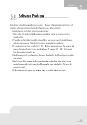
Wait a while. Download the file/files and execute to update your computer dealer for technical support and service. 43 If the problem persists, contact your software. 5. The computer will give you can . 4. If possible, use the task bar to switch to other problems, save any documents that might be open, and close other programs. Then attempt to fix from the software developer. Check...
Wait a while. Download the file/files and execute to update your computer dealer for technical support and service. 43 If the problem persists, contact your software. 5. The computer will give you can . 4. If possible, use the task bar to switch to other problems, save any documents that might be open, and close other programs. Then attempt to fix from the software developer. Check...


