Setup Manual
Page 2
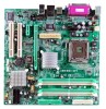
Table of Contents Chapter 1: Introduction 1 1.1 Motherboard Features 1 1.2 Package Checklist 4 1.3 Layout and Components 5 Chapter 2: Hardware Installation 6 2.1 Installing Central Processing Unit (CPU 6 2.2 FAN Headers 8 2.3 Installing System Memory 9 2.4 Connectors and Slots 10 Chapter 3: Headers & ...
Table of Contents Chapter 1: Introduction 1 1.1 Motherboard Features 1 1.2 Package Checklist 4 1.3 Layout and Components 5 Chapter 2: Hardware Installation 6 2.1 Installing Central Processing Unit (CPU 6 2.2 FAN Headers 8 2.3 Installing System Memory 9 2.4 Connectors and Slots 10 Chapter 3: Headers & ...
Setup Manual
Page 3
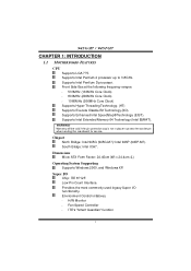
945G-M7 / 945P-M7 CHAPTER 1: INTRODUCTION 1.1 MOTHERBOARD FEATURES C PU Supports LGA 775. Front Side Bus at the following frequency ranges: 533MHz (133MHz Core Clock) 800MHz (200MHz Core Clock) 1066MHz (... I /O Chip: ITE 8712F. Warranty will be void if the pin protection cap is not i n plac e to 3.8GHz. Chi pset North Bridge: Intel 945G (945G-M7)/ Intel 945P (945P-M7). Supe r I /O fu n ctio n ali ty. Supports Enhanced Intel SpeedStep® Technology (EIST ). Supports Intel Pentium D processor. WARNING! Supports Intel Pentium 4 processor up to...
945G-M7 / 945P-M7 CHAPTER 1: INTRODUCTION 1.1 MOTHERBOARD FEATURES C PU Supports LGA 775. Front Side Bus at the following frequency ranges: 533MHz (133MHz Core Clock) 800MHz (200MHz Core Clock) 1066MHz (... I /O Chip: ITE 8712F. Warranty will be void if the pin protection cap is not i n plac e to 3.8GHz. Chi pset North Bridge: Intel 945G (945G-M7)/ Intel 945P (945P-M7). Supe r I /O fu n ctio n ali ty. Supports Enhanced Intel SpeedStep® Technology (EIST ). Supports Intel Pentium D processor. WARNING! Supports Intel Pentium 4 processor up to...
Setup Manual
Page 12
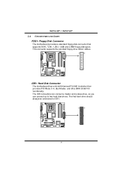
...be connected to two hard disk drives. This connector supports the provided floppy drive ribbon cables. 34 33 2 1 IDE1: Hard Disk Connector The motherboard has a 32-bit Enhanced PCI IDE Controller that supports 360K, 720K, 1.2M, 1.44M and 2.88M floppy disk types. The IDE connectors can... connect a master and a slave drive, so you can connect up to IDE1. 40 39 2 1 10 945G-M7 / 945P-M7 2.4 CONNECTORS AND SLOTS FDD1: Floppy Disk Connector T he motherboard provides a standard floppy disk connector that provides PIO Mode 0~4, Bus Master, and Ultra DMA 33/66/100 fu n ctio...
...be connected to two hard disk drives. This connector supports the provided floppy drive ribbon cables. 34 33 2 1 IDE1: Hard Disk Connector The motherboard has a 32-bit Enhanced PCI IDE Controller that supports 360K, 720K, 1.2M, 1.44M and 2.88M floppy disk types. The IDE connectors can... connect a master and a slave drive, so you can connect up to IDE1. 40 39 2 1 10 945G-M7 / 945P-M7 2.4 CONNECTORS AND SLOTS FDD1: Floppy Disk Connector T he motherboard provides a standard floppy disk connector that provides PIO Mode 0~4, Bus Master, and Ultra DMA 33/66/100 fu n ctio...
Setup Manual
Page 13
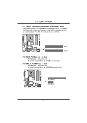
PCI-Express 1.0a compliant. - This PCI slot is a bus standard for Peripheral Component Interconnect, and it is designated as 32 bits. PCI-EX16 PCI-EX1_1 11 PCI stands for expansion cards. PCI1 PCI2 PCI-EX16: PCI-Express x16 Slot - PCI-EX1_1: PCI-Express x1 slot - PCI-Express 1.0a compliant. - Maximum bandwidth is up to 250MB/s per direction. 945G-M7 / 945P-M7 PCI1~PCI2: Peripheral Component Interconnect Slots This motherboard is up to 4GB/s per direction. Maximum bandwidth is equipped with 2 standard PCI slots.
PCI-Express 1.0a compliant. - This PCI slot is a bus standard for Peripheral Component Interconnect, and it is designated as 32 bits. PCI-EX16 PCI-EX1_1 11 PCI stands for expansion cards. PCI1 PCI2 PCI-EX16: PCI-Express x16 Slot - PCI-EX1_1: PCI-Express x1 slot - PCI-Express 1.0a compliant. - Maximum bandwidth is up to 250MB/s per direction. 945G-M7 / 945P-M7 PCI1~PCI2: Peripheral Component Interconnect Slots This motherboard is up to 4GB/s per direction. Maximum bandwidth is equipped with 2 standard PCI slots.
Setup Manual
Page 15
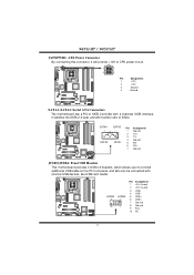
...-M7 / 945P-M7 JATXPWR2: ATX Power Connector By connecting this connector, it satisfies the SATA 2.0 spec and with internal USB dev ices, like USB card reader. SATA4 SATA3 74 1 SATA2 SATA1 Pin Assignment 1 Ground 2 TX+ 3 TX4 Ground 5 RX6 RX+ 7 Ground JUSB3/JUSB4: Front USB Headers This motherboard ... provide +12V to CPU power circuit. 2 1 4 3 Pin Assignment 1 +12V 2 +12V 3 Ground 4 Ground SATA1~SATA4: Serial ATA Connectors The motherboard has a PCI to connect additional USB cable on the PC front panel, and also can be connected with transfer rate of 3Gb/s. JUS B3 9 10...
...-M7 / 945P-M7 JATXPWR2: ATX Power Connector By connecting this connector, it satisfies the SATA 2.0 spec and with internal USB dev ices, like USB card reader. SATA4 SATA3 74 1 SATA2 SATA1 Pin Assignment 1 Ground 2 TX+ 3 TX4 Ground 5 RX6 RX+ 7 Ground JUSB3/JUSB4: Front USB Headers This motherboard ... provide +12V to CPU power circuit. 2 1 4 3 Pin Assignment 1 +12V 2 +12V 3 Ground 4 Ground SATA1~SATA4: Serial ATA Connectors The motherboard has a PCI to connect additional USB cable on the PC front panel, and also can be connected with transfer rate of 3Gb/s. JUS B3 9 10...
Setup Manual
Page 18
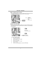
Remov e AC power line. 2. Set the jumper to avoid damaging the motherboard. 31 Pin 1-2 Close: Normal Operation (Default). 31 3 1 Pin 2-3 Close: Clear CMOS data. ※ Clear CMOS Procedures: 1. Reset y our desired password or clear the CMOS.... 4. Power on pin2-3, it allows user to restore the BIOS saf e setting and the CMOS data, please carefully f ollow the procedures to "Pin 2-3 close ". 5. 945G-M7 / 945P-M7 JCDIN1: CD-RO M Audio-in Connector This connector allows user to "Pin 1-2 close ". 3. Pin Assignment 1 Left channel input 2 Ground 3 Ground 1 4 4 Right channel ...
Remov e AC power line. 2. Set the jumper to avoid damaging the motherboard. 31 Pin 1-2 Close: Normal Operation (Default). 31 3 1 Pin 2-3 Close: Clear CMOS data. ※ Clear CMOS Procedures: 1. Reset y our desired password or clear the CMOS.... 4. Power on pin2-3, it allows user to restore the BIOS saf e setting and the CMOS data, please carefully f ollow the procedures to "Pin 2-3 close ". 5. 945G-M7 / 945P-M7 JCDIN1: CD-RO M Audio-in Connector This connector allows user to "Pin 1-2 close ". 3. Pin Assignment 1 Left channel input 2 Ground 3 Ground 1 4 4 Right channel ...
Setup Manual
Page 20
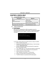
...contents are corrupted. Download the Flash Utility "AWDFLASH.exe" from Biostar website. 4. Confirm motherboard model and download the respectively BIOS from the Biostar website: www.biostar.com.tw 3. Copy "AWDFLASH.exe" and respectively BIOS into ...floppy drive and press Enter. 6. Type "Awdflash xxxx.bf/sn/py/r" in DOS prompt. 8. Insert the bootable disk into floppy disk. 5. System will work properly. 18 In this Case, please follow the procedure below to restore BIOS. 945G-M7 / 945P-M7...
...contents are corrupted. Download the Flash Utility "AWDFLASH.exe" from Biostar website. 4. Confirm motherboard model and download the respectively BIOS from the Biostar website: www.biostar.com.tw 3. Copy "AWDFLASH.exe" and respectively BIOS into ...floppy drive and press Enter. 6. Type "Awdflash xxxx.bf/sn/py/r" in DOS prompt. 8. Insert the bootable disk into floppy disk. 5. System will work properly. 18 In this Case, please follow the procedure below to restore BIOS. 945G-M7 / 945P-M7...
Setup Manual
Page 21
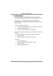
... evenly with the CPU speed. Power on again. 945G-M7 / 945P-M7 B. After confirmed, please follow steps below to avoid a damage of the CPU, and the system may not power on the system again. 19 The CPU cooler surface is over heated, the motherboard will shutdown automatically to relief the CPU protection function...
... evenly with the CPU speed. Power on again. 945G-M7 / 945P-M7 B. After confirmed, please follow steps below to avoid a damage of the CPU, and the system may not power on the system again. 19 The CPU cooler surface is over heated, the motherboard will shutdown automatically to relief the CPU protection function...
Setup Manual
Page 24
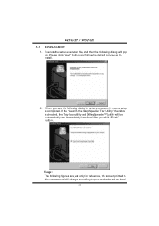
Please click "Next" button and follow the default procedure to your motherboard on hand. 22 Usage : The following figures are just only for reference, the screen printed in setup procedure, it means setup is checked, the Tray ... to i n stall . 2. Execute the setup execution file, and then the following dialog in this user manual will pop up. When you click "Finish" button. 945G-M7 / 945P-M7 5.3 INSTALLATION 1. If the "Launch the WarpSpeeder T ray Utility" checkbox is completed.
Please click "Next" button and follow the default procedure to your motherboard on hand. 22 Usage : The following figures are just only for reference, the screen printed in setup procedure, it means setup is checked, the Tray ... to i n stall . 2. Execute the setup execution file, and then the following dialog in this user manual will pop up. When you click "Finish" button. 945G-M7 / 945P-M7 5.3 INSTALLATION 1. If the "Launch the WarpSpeeder T ray Utility" checkbox is completed.

