Setup Manual
Page 3
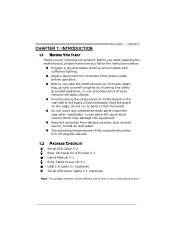
...you start installing the motherboard, please make sure you follow the instructions below: „ Prepare a dry and stable working environment with sufficient lighting. „ Always disconnect the computer from power outlet before operation. „ Before you for ATX Case X 1 User's Manual X 1 Fully Setup...1.2 PACKAGE CHECKLIST Serial ATA Cable X 2 Rear I/O Panel for choosing our product. CHAPTER 1: INTRODUCTION H61MGC / H61MLC 1.1 BEFORE YOU START Thank you take the motherboard out from dangerous area, such as heat source, humid air and water. „ The operating temperatures of the ...
...you start installing the motherboard, please make sure you follow the instructions below: „ Prepare a dry and stable working environment with sufficient lighting. „ Always disconnect the computer from power outlet before operation. „ Before you for ATX Case X 1 User's Manual X 1 Fully Setup...1.2 PACKAGE CHECKLIST Serial ATA Cable X 2 Rear I/O Panel for choosing our product. CHAPTER 1: INTRODUCTION H61MGC / H61MLC 1.1 BEFORE YOU START Thank you take the motherboard out from dangerous area, such as heat source, humid air and water. „ The operating temperatures of the ...
Setup Manual
Page 4
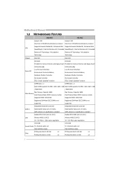
... x16 Slot x1 PCI Express Gen2 x16 Slot x1 Slots PCI Express Gen2 x1 Slot x2 PCI Express Gen2 x1 Slot x2 2 Super I /O functionality. Motherboard Manual 1.3 MOTHERBOARD FEATURES H61MGC H61MLC Socket 1155 Socket 1155 Intel Core i7/i5/i3/Pentium/Celeron processor Intel Core i7/i5/i3/Pentium/Celeron processor Supports Execute Disable Bit...
... x16 Slot x1 PCI Express Gen2 x16 Slot x1 Slots PCI Express Gen2 x1 Slot x2 PCI Express Gen2 x1 Slot x2 2 Super I /O functionality. Motherboard Manual 1.3 MOTHERBOARD FEATURES H61MGC H61MLC Socket 1155 Socket 1155 Intel Core i7/i5/i3/Pentium/Celeron processor Intel Core i7/i5/i3/Pentium/Celeron processor Supports Execute Disable Bit...
Setup Manual
Page 6
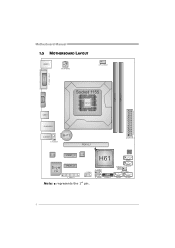
Motherboard Manual 1.5 MOTHERBOARD LAYOUT KBMS1 ATXPW R 2 CPU_FAN1 ( H61MGC ) DVI1 VGA1 DDR3_A1 DDR3_B1 Socket 1155 CP U 1 USB1 RJ45USB1 AUDIO1 F_AUDIO1 BAT1 PEX16_1 ATXPW R 1 CODEC PEX1_1 LAN H61 Super I/O PEX1_2 J_COM1 F_USB1 J_ PRINT1 F_USB2 PANEL1 Note: ■ represents the 1st pin. BIOS SATA1 JCMOS 1 SATA 2 SYS_ FAN1 SATA 3 SATA4 4
Motherboard Manual 1.5 MOTHERBOARD LAYOUT KBMS1 ATXPW R 2 CPU_FAN1 ( H61MGC ) DVI1 VGA1 DDR3_A1 DDR3_B1 Socket 1155 CP U 1 USB1 RJ45USB1 AUDIO1 F_AUDIO1 BAT1 PEX16_1 ATXPW R 1 CODEC PEX1_1 LAN H61 Super I/O PEX1_2 J_COM1 F_USB1 J_ PRINT1 F_USB2 PANEL1 Note: ■ represents the 1st pin. BIOS SATA1 JCMOS 1 SATA 2 SYS_ FAN1 SATA 3 SATA4 4
Setup Manual
Page 8
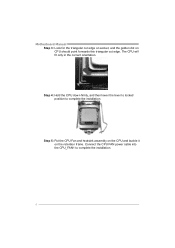
Step 5: Put the CPU Fan and heatsink assembly on the CPU and buckle it on CPU should point forwards this triangular cut edge. Step 4: Hold the CPU down firmly, and then lower the lever to locked position to complete the installation. 6 Motherboard Manual Step 3: Look for the triangular cut edge on socket, and the golden dot on the retention frame. Connect the CPU FAN power cable into the CPU_FAN1 to complete the installation. The CPU will fit only in the correct orientation.
Step 5: Put the CPU Fan and heatsink assembly on the CPU and buckle it on CPU should point forwards this triangular cut edge. Step 4: Hold the CPU down firmly, and then lower the lever to locked position to complete the installation. 6 Motherboard Manual Step 3: Look for the triangular cut edge on socket, and the golden dot on the retention frame. Connect the CPU FAN power cable into the CPU_FAN1 to complete the installation. The CPU will fit only in the correct orientation.
Setup Manual
Page 10
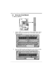
D DR3_A1 DD R3_B1 Motherboard Manual 2.3 INSTALLING SYSTEM MEMORY A. Align a DIMM on the slot such that the notch on the DIMM matches the break on the Slot. 2. Insert the DIMM vertically and firmly into the slot until the retaining chip snap back in place and the DIMM is properly seated. 8 Unlock a DIMM slot by pressing the retaining clips outward. Memory Modules 1.
D DR3_A1 DD R3_B1 Motherboard Manual 2.3 INSTALLING SYSTEM MEMORY A. Align a DIMM on the slot such that the notch on the DIMM matches the break on the Slot. 2. Insert the DIMM vertically and firmly into the slot until the retaining chip snap back in place and the DIMM is properly seated. 8 Unlock a DIMM slot by pressing the retaining clips outward. Memory Modules 1.
Setup Manual
Page 12
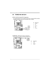
Motherboard Manual 2.4 CONNECTORS AND SLOTS SATA1~SATA4: Serial ATA Connectors The motherboard has a PCI to CPU power circuit. 2 1 3 4 Pin Assignment 1 +12V 2 +12V 3 Ground 4 Ground 10 SATA 1 SATA 2 SATA3 SATA4 7 41 Pin Assignment 1 Ground 2 TX+ 3 TX4 Ground 5 RX6 RX+ 7 Ground ATXPWR2: ATX Power Source Connector This connector provides +12V to SATA Controller with 4 channels SATA2 interface, it satisfies the SATA 2.0 spec and with transfer rate of 3.0Gb/s.
Motherboard Manual 2.4 CONNECTORS AND SLOTS SATA1~SATA4: Serial ATA Connectors The motherboard has a PCI to CPU power circuit. 2 1 3 4 Pin Assignment 1 +12V 2 +12V 3 Ground 4 Ground 10 SATA 1 SATA 2 SATA3 SATA4 7 41 Pin Assignment 1 Ground 2 TX+ 3 TX4 Ground 5 RX6 RX+ 7 Ground ATXPWR2: ATX Power Source Connector This connector provides +12V to SATA Controller with 4 channels SATA2 interface, it satisfies the SATA 2.0 spec and with transfer rate of 3.0Gb/s.

Setup Manual
Page 14
Data transfer bandwidth up to 500MB/s per direction, for an aggregate of 16GB/s totally. - PCI-Express supports a raw bit-rate of 5.0Gb/s on the data pins. PEX1_1: PCI-Express Gen2 x1 Slot - PEX16_1 PEX1_1 PEX1_2 12 PCI-Express Gen2 supports a raw bit-rate of 2.5Gb/s on the data pins. - 2X bandwidth over the PCI-Express 1.1 architecture. Maximum theoretical realized bandwidth of 8GB/s simultaneously per direction; 1GB/s in total. - PCI-Express 2.0 compliant. - PCI-Express 2.0 compliant. - Motherboard Manual PEX16_1: PCI-Express Gen2 x16 Slot -
Data transfer bandwidth up to 500MB/s per direction, for an aggregate of 16GB/s totally. - PCI-Express supports a raw bit-rate of 5.0Gb/s on the data pins. PEX1_1: PCI-Express Gen2 x1 Slot - PEX16_1 PEX1_1 PEX1_2 12 PCI-Express Gen2 supports a raw bit-rate of 2.5Gb/s on the data pins. - 2X bandwidth over the PCI-Express 1.1 architecture. Maximum theoretical realized bandwidth of 8GB/s simultaneously per direction; 1GB/s in total. - PCI-Express 2.0 compliant. - PCI-Express 2.0 compliant. - Motherboard Manual PEX16_1: PCI-Express Gen2 x16 Slot -
Setup Manual
Page 16
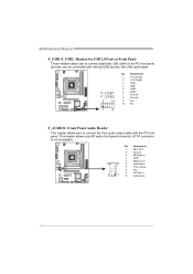
... Header This header allows user to connect additional USB cable on the PC front panel, and also can be connected with the PC front panel. Motherboard Manual F_USB1/F_USB2: Headers for USB 2.0 Ports at Front Panel These headers allow user to connect the front audio output cable with internal USB devices, like...
... Header This header allows user to connect additional USB cable on the PC front panel, and also can be connected with the PC front panel. Motherboard Manual F_USB1/F_USB2: Headers for USB 2.0 Ports at Front Panel These headers allow user to connect the front audio output cable with internal USB devices, like...
Setup Manual
Page 18
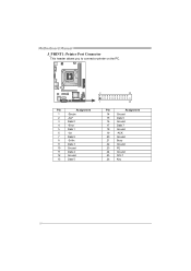
Pin Assignment 1 -Strobe 2 -ALF 3 Data 0 4 -Error 5 Data 1 6 -Init 7 Data 2 8 -Scltin 9 Data 3 10 Ground 11 Data 4 12 Ground 13 Data 5 2 26 1 25 Pin Assignment 14 Ground 15 Data 6 16 Ground 17 Data 7 18 Ground 19 -ACK 20 Ground 21 Busy 22 Ground 23 PE 24 Ground 25 SCLT 26 Key 16 Motherboard Manual J_PRINT1: Printer Port Connector This header allows you to connector printer on the PC.
Pin Assignment 1 -Strobe 2 -ALF 3 Data 0 4 -Error 5 Data 1 6 -Init 7 Data 2 8 -Scltin 9 Data 3 10 Ground 11 Data 4 12 Ground 13 Data 5 2 26 1 25 Pin Assignment 14 Ground 15 Data 6 16 Ground 17 Data 7 18 Ground 19 -ACK 20 Ground 21 Busy 22 Ground 23 PE 24 Ground 25 SCLT 26 Key 16 Motherboard Manual J_PRINT1: Printer Port Connector This header allows you to connector printer on the PC.
Setup Manual
Page 19
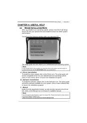
Click on the Manual icon to open the manual file. H61MGC / H61MLC CHAPTER 4: USEFUL HELP 4.1 DRIVER INSTALLATION NOTE After you insert the CD The setup guide will auto detect your motherboard and operating system. You will list the compatible driver for your system, click on each software title to launch ... use file browser to launch the installation program. B. Software Installation To install the software, please click on the Driver icon. Manual Aside from http://www.adobe.com /produ cts/a crobat /reads tep2 .html 17 Note: You will list the software available for available...
Click on the Manual icon to open the manual file. H61MGC / H61MLC CHAPTER 4: USEFUL HELP 4.1 DRIVER INSTALLATION NOTE After you insert the CD The setup guide will auto detect your motherboard and operating system. You will list the compatible driver for your system, click on each software title to launch ... use file browser to launch the installation program. B. Software Installation To install the software, please click on the Driver icon. Manual Aside from http://www.adobe.com /produ cts/a crobat /reads tep2 .html 17 Note: You will list the software available for available...
Setup Manual
Page 20
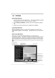
... which is a convenient utility that you will collect the system information which would appear if the Autorun function has been enabled. 2. Send the mail out. Motherboard Manual 4.2 SOFTWARE Installing Software 1. Follow the on the desktop. This utility will see the software icon "eHOT Line" / "BIOS Update" appears on -screen instructions to a .txt...
... which is a convenient utility that you will collect the system information which would appear if the Autorun function has been enabled. 2. Send the mail out. Motherboard Manual 4.2 SOFTWARE Installing Software 1. Follow the on the desktop. This utility will see the software icon "eHOT Line" / "BIOS Update" appears on -screen instructions to a .txt...
Setup Manual
Page 22
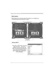
Motherboard Manual BIOS Update BIOS Update is a convenient utility which allows you to a .bin file Update BIOS with a BIOS file Once click on this button, the saving dialog will show. AWARD BIOS Show current BIOS information AMI BIOS Clear CMOS function (Only for AWARD BIOS) Save current BIOS to update your motherboard BIOS under Windows system. Choose the position to save file and enter file name. (We recommend that the file name should be English/number and no longer than 7 characters.) Then click Save. 20
Motherboard Manual BIOS Update BIOS Update is a convenient utility which allows you to a .bin file Update BIOS with a BIOS file Once click on this button, the saving dialog will show. AWARD BIOS Show current BIOS information AMI BIOS Clear CMOS function (Only for AWARD BIOS) Save current BIOS to update your motherboard BIOS under Windows system. Choose the position to save file and enter file name. (We recommend that the file name should be English/number and no longer than 7 characters.) Then click Save. 20
Setup Manual
Page 24
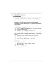
Motherboard Manual 4.3 EXTRA INFORMATION CPU Overheated If the system shuts down automatically after system is powered on for seconds. 3. CPU fan is over heated, the motherboard will shutdown automatically to relief the CPU protection function. 1. After confirmed, please follow steps below to avoid a damage of the CPU, and the system may ...
Motherboard Manual 4.3 EXTRA INFORMATION CPU Overheated If the system shuts down automatically after system is powered on for seconds. 3. CPU fan is over heated, the motherboard will shutdown automatically to relief the CPU protection function. 1. After confirmed, please follow steps below to avoid a damage of the CPU, and the system may ...
Setup Manual
Page 26
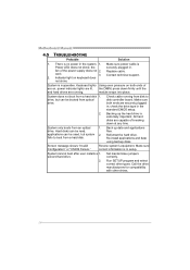
... the securely plugged in the system. 1. Contact technical support. 2. drive. Back up the hard drive is no power in . Review system's equipment. second hard drive. 2. Motherboard Manual 4.5 TROUBLESHOOTING Probable Solution 1. There is extremely important. Indicator light on , power indicator lights are lit, the DIMM, press down firmly until the and hard drives...
... the securely plugged in the system. 1. Contact technical support. 2. drive. Back up the hard drive is no power in . Review system's equipment. second hard drive. 2. Motherboard Manual 4.5 TROUBLESHOOTING Probable Solution 1. There is extremely important. Indicator light on , power indicator lights are lit, the DIMM, press down firmly until the and hard drives...
Setup Manual
Page 44
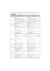
Motherboard Manual JAPANESE H61MGC H61MLC Socket 1155 Socket 1155 Intel Core i7/i5/i3/Pentium/Celeron Intel Core i7/i5/i3/Pentium/Celeron Execute Disable Bit / Enhanced Intel Execute Disable ...
Motherboard Manual JAPANESE H61MGC H61MLC Socket 1155 Socket 1155 Intel Core i7/i5/i3/Pentium/Celeron Intel Core i7/i5/i3/Pentium/Celeron Execute Disable Bit / Enhanced Intel Execute Disable ...


