User Guide
Page 17
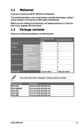
...above items is damaged or missing, contact your motherboard package for buying an ASUS® Z9PR-D16 motherboard! Standard Gift Box Pack 1 1 6 1 1 1 1 1 1pc per carton Standard Bulk Pack 1 --1 1 1 1 1 10pcs per carton If any of ASUS quality motherboards! Optional items PIKE 2108 PIKE 2008/IMR PIKE 2008 PIKE ...8-port SAS2 6G RAID card LSI 8-port SAS2 6G RAID card LSI 8-port SAS2 6G RAID card LSI 8-port SAS2 6G RAID card ASUS Z9PR-D16 1-3 1.1 Welcome! Thank you start installing the motherboard, and hardware devices on it another standout in your package with the list below. 1.2...
...above items is damaged or missing, contact your motherboard package for buying an ASUS® Z9PR-D16 motherboard! Standard Gift Box Pack 1 1 6 1 1 1 1 1 1pc per carton Standard Bulk Pack 1 --1 1 1 1 1 10pcs per carton If any of ASUS quality motherboards! Optional items PIKE 2108 PIKE 2008/IMR PIKE 2008 PIKE ...8-port SAS2 6G RAID card LSI 8-port SAS2 6G RAID card LSI 8-port SAS2 6G RAID card LSI 8-port SAS2 6G RAID card ASUS Z9PR-D16 1-3 1.1 Welcome! Thank you start installing the motherboard, and hardware devices on it another standout in your package with the list below. 1.2...
User Guide
Page 19
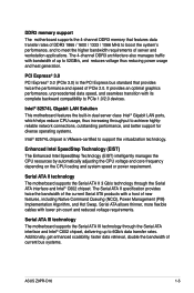
... Serial ATA products with lower pin count and reduced voltage requirements. Additionally, get enhanced scalability, faster data retrieval, double the bandwidth of current bus systems. ASUS Z9PR-D16 1-5 Enhanced Intel SpeedStep Technology (EIST) The Enhanced Intel SpeedStep Technology (EIST) intelligently manages the CPU resources by automatically adjusting the CPU voltage and core frequency...
... Serial ATA products with lower pin count and reduced voltage requirements. Additionally, get enhanced scalability, faster data retrieval, double the bandwidth of current bus systems. ASUS Z9PR-D16 1-5 Enhanced Intel SpeedStep Technology (EIST) The Enhanced Intel SpeedStep Technology (EIST) intelligently manages the CPU resources by automatically adjusting the CPU voltage and core frequency...
User Guide
Page 22
Chapter summary 2 2.1 Before you proceed 2-3 2.2 Motherboard overview 2-4 2.3 Central Processing Unit (CPU 2-8 2.4 System memory 2-14 2.5 Expansion slots 2-17 2.6 Onboard LEDs 2-21 2.7 Jumpers 2-23 2.8 Connectors 2-27 ASUS Z9PR-D16
Chapter summary 2 2.1 Before you proceed 2-3 2.2 Motherboard overview 2-4 2.3 Central Processing Unit (CPU 2-8 2.4 System memory 2-14 2.5 Expansion slots 2-17 2.6 Onboard LEDs 2-21 2.7 Jumpers 2-23 2.8 Connectors 2-27 ASUS Z9PR-D16
User Guide
Page 23
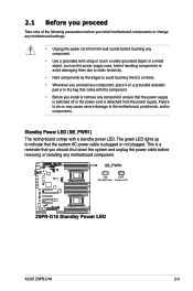
... . • Whenever you install or remove any component, ensure that the power supply is switched off or the power cord is plugged or not plugged. ASUS Z9PR-D16 2-3 This is a reminder that the system AC power cable is detached from the wall socket before touching any component. • Use a grounded wrist strap or...
... . • Whenever you install or remove any component, ensure that the power supply is switched off or the power cord is plugged or not plugged. ASUS Z9PR-D16 2-3 This is a reminder that the system AC power cable is detached from the wall socket before touching any component. • Use a grounded wrist strap or...
User Guide
Page 25
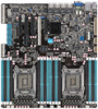
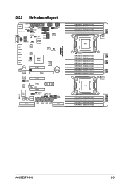
2.2.3 Motherboard layout ASUS Z9PR-D16 2-5
2.2.3 Motherboard layout ASUS Z9PR-D16 2-5
User Guide
Page 29
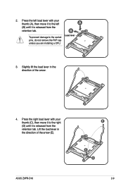
Press the left load lever with your thumb (A), then move it to the right (D) until it is released from the retention tab. Press the right load lever with your thumb (C), then move it to the socket pins, do not remove the PnP cap unless you are installing a CPU. A B To prevent damage to the left (B) until it is released from the retention tab. Load lever 3. ASUS Z9PR-D16 E C D 2-9 Slightly lift the load lever in the direction of the arrow. 4. Lift the load lever in the direction of the arrow (E). 2.
Press the left load lever with your thumb (A), then move it to the right (D) until it is released from the retention tab. Press the right load lever with your thumb (C), then move it to the socket pins, do not remove the PnP cap unless you are installing a CPU. A B To prevent damage to the left (B) until it is released from the retention tab. Load lever 3. ASUS Z9PR-D16 E C D 2-9 Slightly lift the load lever in the direction of the arrow. 4. Lift the load lever in the direction of the arrow (E). 2.
User Guide
Page 31
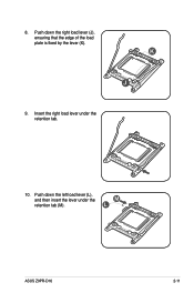
Push down the right load lever (J), ensuring that the edge of the load plate is fixed by the lever (K). K J 9. Push down the left load lever (L), and then insert the lever under the retention tab. 10. 8. Insert the right load lever under the retention tab (M). M L ASUS Z9PR-D16 2-11
Push down the right load lever (J), ensuring that the edge of the load plate is fixed by the lever (K). K J 9. Push down the left load lever (L), and then insert the lever under the retention tab. 10. 8. Insert the right load lever under the retention tab (M). M L ASUS Z9PR-D16 2-11
User Guide
Page 33
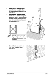
ASUS Z9PR-D16 2-13 D A C C B D B Fasten the screws to just about the proper tightness to the CPU_FAN1 connector on the motherboard. Connect the fan connector to avoid damaging the ...
ASUS Z9PR-D16 2-13 D A C C B D B Fasten the screws to just about the proper tightness to the CPU_FAN1 connector on the motherboard. Connect the fan connector to avoid damaging the ...
User Guide
Page 37
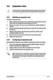
... a chassis). 3. Replace the system cover. 2.5.2 Configuring an expansion card After installing the expansion card, configure it and make the necessary hardware settings for later use . ASUS Z9PR-D16 2-17 Assign an IRQ to the tables on shared slots, ensure that the drivers support "Share IRQ" or that the cards do so may cause...
... a chassis). 3. Replace the system cover. 2.5.2 Configuring an expansion card After installing the expansion card, configure it and make the necessary hardware settings for later use . ASUS Z9PR-D16 2-17 Assign an IRQ to the tables on shared slots, ensure that the drivers support "Share IRQ" or that the cards do so may cause...
User Guide
Page 39
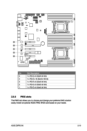
Install an optional ASUS PIKE RAID card based on your preferred SAS solution easily. Slot Description 5 1 x PCI-E x 8 (Gen3 x8 link) 4 1 x PCI-E x 16 (Gen3 x16 link) 3 1 x PCI-E x 8 (Gen3 x8 link) 2 1 x PCI-E x 8 (Gen3 x8 link) 1 1 x PCI-E x 8 (Gen3 x8 link) 2.5.6 PIKE slots The PIKE slot allows you to choose and change your needs. No. ASUS Z9PR-D16 2-19
Install an optional ASUS PIKE RAID card based on your preferred SAS solution easily. Slot Description 5 1 x PCI-E x 8 (Gen3 x8 link) 4 1 x PCI-E x 16 (Gen3 x16 link) 3 1 x PCI-E x 8 (Gen3 x8 link) 2 1 x PCI-E x 8 (Gen3 x8 link) 1 1 x PCI-E x 8 (Gen3 x8 link) 2.5.6 PIKE slots The PIKE slot allows you to choose and change your needs. No. ASUS Z9PR-D16 2-19
User Guide
Page 41
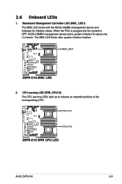
2.6 Onboard LEDs 1. The BMC LED blinks after system initiation finishes. 2. When the PSU is plugged and the system is OFF, ASUS ASMB6 management device starts system initiation for about one (1) minute. ASUS Z9PR-D16 2-21 Baseboard Management Controller LED (BMC_LED1) The BMC LED works with the ASUS ASMB6 management device and indicates its initiation status. CPU warning LED (ERR_CPU1/2) The CPU warning LEDs light up to indicate an impending failure of the corresponding CPU.
2.6 Onboard LEDs 1. The BMC LED blinks after system initiation finishes. 2. When the PSU is plugged and the system is OFF, ASUS ASMB6 management device starts system initiation for about one (1) minute. ASUS Z9PR-D16 2-21 Baseboard Management Controller LED (BMC_LED1) The BMC LED works with the ASUS ASMB6 management device and indicates its initiation status. CPU warning LED (ERR_CPU1/2) The CPU warning LEDs light up to indicate an impending failure of the corresponding CPU.

User Guide
Page 43
... computer and unplug the power cord. 2. Removing the cap will cause system boot failure! The onboard button cell battery powers the RAM data in CMOS. ASUS Z9PR-D16 2-23 After the CMOS clearance, reinstall the battery. Move the jumper cap from pins 1-2 (default) to re-enter data. Plug the power cord and turn...
... computer and unplug the power cord. 2. Removing the cap will cause system boot failure! The onboard button cell battery powers the RAM data in CMOS. ASUS Z9PR-D16 2-23 After the CMOS clearance, reinstall the battery. Move the jumper cap from pins 1-2 (default) to re-enter data. Plug the power cord and turn...
User Guide
Page 45
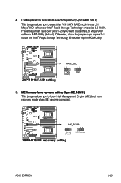
... software RAID Utility (default). 4. Place the jumper caps over pins 1-2 if you to use LSI MegaRAID software or Intel® Rapid Storage Technology enterprise 3.0 RAID. ASUS Z9PR-D16 2-25 Otherwise, place the jumper caps to pins 2-3 to use the Intel® Rapid Storage Technology Enterprise Option ROM Utility. 5 M��E��fi...
... software RAID Utility (default). 4. Place the jumper caps over pins 1-2 if you to use LSI MegaRAID software or Intel® Rapid Storage Technology enterprise 3.0 RAID. ASUS Z9PR-D16 2-25 Otherwise, place the jumper caps to pins 2-3 to use the Intel® Rapid Storage Technology Enterprise Option ROM Utility. 5 M��E��fi...
User Guide
Page 47
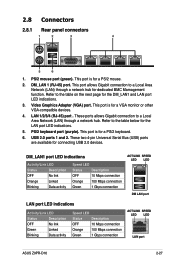
... Blinking Data activity Speed LED Status Description OFF 10 Mbps connection Orange 100 Mbps connection Green 1 Gbps connection ACT/LINK SPEED LED LED LAN port ASUS Z9PR-D16 2-27 This port is for connecting USB 2.0 devices. Refer to a Local Area Network (LAN) through a network hub. This port is for the DM_LAN1 and LAN...
... Blinking Data activity Speed LED Status Description OFF 10 Mbps connection Orange 100 Mbps connection Green 1 Gbps connection ACT/LINK SPEED LED LED LAN port ASUS Z9PR-D16 2-27 This port is for connecting USB 2.0 devices. Refer to a Local Area Network (LAN) through a network hub. This port is for the DM_LAN1 and LAN...
User Guide
Page 49
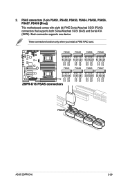
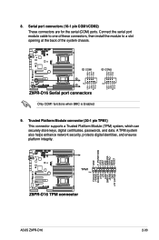
ASUS Z9PR-D16 2-29 These connectors function only when you install a PIKE RAID card. PSAS connectors (7-pin PSAS1, PSAS2, PSAS3, PSAS4, PSAS5, PSAS6, PSAS7, PSAS8 [Blue]) This motherboard comes with eight (8) PIKE Serial Attached SCSI (PSAS) connectors that supports both Serial Attached SCSI (SAS) and Serial ATA (SATA). Each connector supports one device. 2.
ASUS Z9PR-D16 2-29 These connectors function only when you install a PIKE RAID card. PSAS connectors (7-pin PSAS1, PSAS2, PSAS3, PSAS4, PSAS5, PSAS6, PSAS7, PSAS8 [Blue]) This motherboard comes with eight (8) PIKE Serial Attached SCSI (PSAS) connectors that supports both Serial Attached SCSI (SAS) and Serial ATA (SATA). Each connector supports one device. 2.
User Guide
Page 51
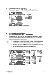
... connector. • DO NOT forget to connect the fan cables to the fan connectors on the fan connectors! • All fans feature the ASUS Fan Speed Control technology. ASUS Z9PR-D16 2-31 Connect the fan cables to the fan connectors. VGA connector (10-1 pin VGA_HDR1) This connector supports the VGA High Dynamic-Range interface...
... connector. • DO NOT forget to connect the fan cables to the fan connectors on the fan connectors! • All fans feature the ASUS Fan Speed Control technology. ASUS Z9PR-D16 2-31 Connect the fan cables to the fan connectors. VGA connector (10-1 pin VGA_HDR1) This connector supports the VGA High Dynamic-Range interface...
User Guide
Page 53
.... 9. Connect the serial port module cable to one of these connectors, then install the module to a slot opening at the back of the system chassis. ASUS Z9PR-D16 2-33
.... 9. Connect the serial port module cable to one of these connectors, then install the module to a slot opening at the back of the system chassis. ASUS Z9PR-D16 2-33
User Guide
Page 55
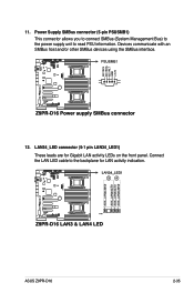
Power Supply SMBus connector (5-pin PSUSMB1) This connector allows you to connect SMBus (System Management Bus) to the power supply unit to the backplane for Gigabit LAN activity LEDs on the front panel. Connect the LAN LED cable to read PSU information. ASUS Z9PR-D16 2-35 Devices communicate with an SMBus host and/or other SMBus devices using the SMBus interface. 12. LAN34_LED connector (5-1 pin LAN34_LED1) These leads are for LAN activity indication. 11.
Power Supply SMBus connector (5-pin PSUSMB1) This connector allows you to connect SMBus (System Management Bus) to the power supply unit to the backplane for Gigabit LAN activity LEDs on the front panel. Connect the LAN LED cable to read PSU information. ASUS Z9PR-D16 2-35 Devices communicate with an SMBus host and/or other SMBus devices using the SMBus interface. 12. LAN34_LED connector (5-1 pin LAN34_LED1) These leads are for LAN activity indication. 11.
User Guide
Page 57
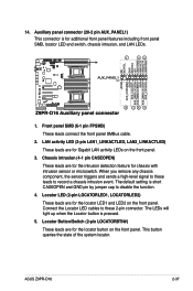
.... Front panel SMB (6-1 pin FPSMB) These leads connect the front panel SMBus cable. 2. Connect the Locator LED cables to these leads to disable the function. 4. ASUS Z9PR-D16 2-37 Locator LED (2-pin LOCATORLED1, LOCATORLED2) These leads are for Gigabit LAN activity LEDs on the front panel. 3. This button queries the state of the...
.... Front panel SMB (6-1 pin FPSMB) These leads connect the front panel SMBus cable. 2. Connect the Locator LED cables to these leads to disable the function. 4. ASUS Z9PR-D16 2-37 Locator LED (2-pin LOCATORLED1, LOCATORLED2) These leads are for Gigabit LAN activity LEDs on the front panel. 3. This button queries the state of the...
User Guide
Page 60
Chapter summary 3 3.1 Starting up for the first time 3-3 3.2 Powering off the computer 3-4 ASUS Z9PR-D16
Chapter summary 3 3.1 Starting up for the first time 3-3 3.2 Powering off the computer 3-4 ASUS Z9PR-D16

