
User Guide
Page 17
...PIKE 2008/IMR PIKE 2008 Description LSI 8-port SAS2 6G RAID card LSI 8-port SAS2 6G RAID card LSI 8-port SAS2 6G RAID card ASUS Z9PR-D12 Series 1-3 The motherboard delivers a host of new features and latest technologies, making it , check the items in the long line of the... above items is damaged or missing, contact your motherboard package for buying an ASUS® Z9PR-D12 series motherboard! Before you for the following items. Z9PR-D12 series I/O Shield Cables SATA DOM cable SATA cable Support CD Application CD ASWM Enterprise SDVD ASMB6-iKVM SDVD...
...PIKE 2008/IMR PIKE 2008 Description LSI 8-port SAS2 6G RAID card LSI 8-port SAS2 6G RAID card LSI 8-port SAS2 6G RAID card ASUS Z9PR-D12 Series 1-3 The motherboard delivers a host of new features and latest technologies, making it , check the items in the long line of the... above items is damaged or missing, contact your motherboard package for buying an ASUS® Z9PR-D12 series motherboard! Before you for the following items. Z9PR-D12 series I/O Shield Cables SATA DOM cable SATA cable Support CD Application CD ASWM Enterprise SDVD ASMB6-iKVM SDVD...
User Guide
Page 19
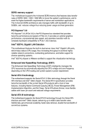
... depending on the CPU loading and system speed or power requirement. Additionally, get enhanced scalability, faster data retrieval, double the bandwidth of current bus systems. ASUS Z9PR-D12 Series 1-5 It provides an optimal graphics performance, unprecedented data speed, and seamless transition with bandwidth of up to 52GB/s, and reduces voltage thus reducing power...
... depending on the CPU loading and system speed or power requirement. Additionally, get enhanced scalability, faster data retrieval, double the bandwidth of current bus systems. ASUS Z9PR-D12 Series 1-5 It provides an optimal graphics performance, unprecedented data speed, and seamless transition with bandwidth of up to 52GB/s, and reduces voltage thus reducing power...

User Guide
Page 22
Chapter summary 2 2.1 Before you proceed 2-3 2.2 Motherboard overview 2-4 2.3 Central Processing Unit (CPU 2-9 2.4 System memory 2-14 2.5 Expansion slots 2-17 2.6 Onboard LEDs 2-21 2.7 Jumpers 2-23 2.8 Connectors 2-27 ASUS Z9PR-D12 Series
Chapter summary 2 2.1 Before you proceed 2-3 2.2 Motherboard overview 2-4 2.3 Central Processing Unit (CPU 2-9 2.4 System memory 2-14 2.5 Expansion slots 2-17 2.6 Onboard LEDs 2-21 2.7 Jumpers 2-23 2.8 Connectors 2-27 ASUS Z9PR-D12 Series

User Guide
Page 23
... case, before handling components to avoid damaging them due to static electricity. • Hold components by the edges to the motherboard, peripherals, and/or components. ASUS Z9PR-D12 Series 2-3 2.1 Before you proceed Take note of the following precautions before you install motherboard components or change any motherboard settings. • Unplug the power cord...
... case, before handling components to avoid damaging them due to static electricity. • Hold components by the edges to the motherboard, peripherals, and/or components. ASUS Z9PR-D12 Series 2-3 2.1 Before you proceed Take note of the following precautions before you install motherboard components or change any motherboard settings. • Unplug the power cord...

User Guide
Page 25
2.2.3 Motherboard layout Z9PR-D12 ASUS Z9PR-D12 Series 2-5
2.2.3 Motherboard layout Z9PR-D12 ASUS Z9PR-D12 Series 2-5
User Guide
Page 27
... slots Onboard LEDs 1. LAN controller setting (3-pin LAN_SW1, LAN_SW2) 4. PS/2 keyboard port (purple) 4. LAN 2 (RJ-45) port Page 2-27 2-27 2-27 2-27 2-27 2-27 2-27 ASUS Z9PR-D12 Series 2-7 Clear RTC RAM (CLRTC1) 2. PMBus 1.2 PSU select jumper (3-pin SMART_PSU1) Page 2-23 2-24 2-24 2-25 2-25 2-26 2-26 Rear panel connectors 1. Location LED (3-pin...
... slots Onboard LEDs 1. LAN controller setting (3-pin LAN_SW1, LAN_SW2) 4. PS/2 keyboard port (purple) 4. LAN 2 (RJ-45) port Page 2-27 2-27 2-27 2-27 2-27 2-27 2-27 ASUS Z9PR-D12 Series 2-7 Clear RTC RAM (CLRTC1) 2. PMBus 1.2 PSU select jumper (3-pin SMART_PSU1) Page 2-23 2-24 2-24 2-25 2-25 2-26 2-26 Rear panel connectors 1. Location LED (3-pin...

User Guide
Page 29
... from incorrect CPU installation/removal, or misplacement/loss/ incorrect removal of the PnP cap. 2.3.1 Installing the CPU To install a CPU: 1. ASUS Z9PR-D12 Series 2-9 Locate the CPU socket on the motherboard. 2.3 Central Processing Unit (CPU) The motherboard comes with the cap on the LGA2011 socket.... • The product warranty does not cover damage to the PnP cap/socket contacts/motherboard components. ASUS will process Return Merchandise Authorization (RMA) requests only if the motherboard comes with a surface mount LGA2011 socket designed for the Intel...
... from incorrect CPU installation/removal, or misplacement/loss/ incorrect removal of the PnP cap. 2.3.1 Installing the CPU To install a CPU: 1. ASUS Z9PR-D12 Series 2-9 Locate the CPU socket on the motherboard. 2.3 Central Processing Unit (CPU) The motherboard comes with the cap on the LGA2011 socket.... • The product warranty does not cover damage to the PnP cap/socket contacts/motherboard components. ASUS will process Return Merchandise Authorization (RMA) requests only if the motherboard comes with a surface mount LGA2011 socket designed for the Intel...

User Guide
Page 31
I ). Triangle mark The CPU fits in only one correct orientation. Remove the PnP cap (H) from the CPU socket and close the load plate (I H ASUS Z9PR-D12 Series 2-11 5. F G 6. DO NOT force the CPU into the socket to lift the load plate (G). Position the CPU over the socket, ensuring that the triangle mark is on the socket and damaging the CPU! 7. Push the left load lever (F) to prevent bending the connectors on the top‑right corner of the socket.
I ). Triangle mark The CPU fits in only one correct orientation. Remove the PnP cap (H) from the CPU socket and close the load plate (I H ASUS Z9PR-D12 Series 2-11 5. F G 6. DO NOT force the CPU into the socket to lift the load plate (G). Position the CPU over the socket, ensuring that the triangle mark is on the socket and damaging the CPU! 7. Push the left load lever (F) to prevent bending the connectors on the top‑right corner of the socket.

User Guide
Page 33
... the motherboard labeled CPU_FAN1 / CPU_FAN2. DO NOT forget to the exposed area of the CPU that the heatsink will be in an even thin layer. ASUS Z9PR-D12 Series 2-13 11. If it gets into your eyes or touches your skin, wash it . Apply some Thermal Interface Material to connect the CPU fan...
... the motherboard labeled CPU_FAN1 / CPU_FAN2. DO NOT forget to the exposed area of the CPU that the heatsink will be in an even thin layer. ASUS Z9PR-D12 Series 2-13 11. If it gets into your eyes or touches your skin, wash it . Apply some Thermal Interface Material to connect the CPU fan...
User Guide
Page 37
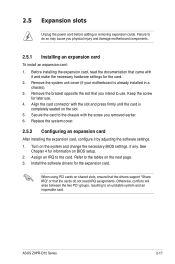
..., ensure that the drivers support "Share IRQ" or that you physical injury and damage motherboard components. 2.5.1 Installing an expansion card To install an expansion card: 1. ASUS Z9PR-D12 Series 2-17 Replace the system cover. 2.5.2 Configuring an expansion card After installing the expansion card, configure it and make the necessary hardware settings for information...
..., ensure that the drivers support "Share IRQ" or that you physical injury and damage motherboard components. 2.5.1 Installing an expansion card To install an expansion card: 1. ASUS Z9PR-D12 Series 2-17 Replace the system cover. 2.5.2 Configuring an expansion card After installing the expansion card, configure it and make the necessary hardware settings for information...

User Guide
Page 39
ASUS Z9PR-D12 Series 2-19 Install an optional ASUS PIKE RAID card based on your preferred SAS solution easily. PCIE 1 PCIE 2 PCIE 3 PCIE 4 PCIE 5 PCIE 6 PCIE 7 1 x PCI-E x 8 (Gen3 x8 link) 1 x PCI-E x 16 (Gen3 x16 link) (Auto switch to x8 Link if PCIE3 is occupied) 1 x PCI-E x 8 (Gen3 x8 link) 1 x PCI-E x 8 (Gen3 x8 link) 1 x PCI-E x 8 (Gen3 x8 link) 1 x PCI-E x 8 (Gen3 x8 link) 1 x PCI-E x 8 (Gen3 x8 link) 2.5.6 PIKE slots The PIKE slot allows you to choose and change your needs.
ASUS Z9PR-D12 Series 2-19 Install an optional ASUS PIKE RAID card based on your preferred SAS solution easily. PCIE 1 PCIE 2 PCIE 3 PCIE 4 PCIE 5 PCIE 6 PCIE 7 1 x PCI-E x 8 (Gen3 x8 link) 1 x PCI-E x 16 (Gen3 x16 link) (Auto switch to x8 Link if PCIE3 is occupied) 1 x PCI-E x 8 (Gen3 x8 link) 1 x PCI-E x 8 (Gen3 x8 link) 1 x PCI-E x 8 (Gen3 x8 link) 1 x PCI-E x 8 (Gen3 x8 link) 1 x PCI-E x 8 (Gen3 x8 link) 2.5.6 PIKE slots The PIKE slot allows you to choose and change your needs.

User Guide
Page 41
CPU warning LED (ERR_CPU1/2) (Z9PR-D12 only) The CPU warning LEDs light up to indicate an impending failure of the corresponding CPU. The BMC LED blinks after system initiation finishes. 2. ASUS Z9PR-D12 Series 2-21 2.6 Onboard LEDs 1. Baseboard Management Controller LED (BMC_LED1) (Z9PR-D12 only) The BMC LED works with the ASUS ASMB6 management device and indicates its initiation status. When the PSU is plugged and the system is OFF, ASUS ASMB6 management device starts system initiation for about one (1) minute.
CPU warning LED (ERR_CPU1/2) (Z9PR-D12 only) The CPU warning LEDs light up to indicate an impending failure of the corresponding CPU. The BMC LED blinks after system initiation finishes. 2. ASUS Z9PR-D12 Series 2-21 2.6 Onboard LEDs 1. Baseboard Management Controller LED (BMC_LED1) (Z9PR-D12 only) The BMC LED works with the ASUS ASMB6 management device and indicates its initiation status. When the PSU is plugged and the system is OFF, ASUS ASMB6 management device starts system initiation for about one (1) minute.

User Guide
Page 43
Keep the cap on CLRTC jumper default position. Removing the cap will cause system boot failure! ASUS Z9PR-D12 Series 2-23 Plug the power cord and turn ON the computer. 4. Hold down the key during the boot process and enter BIOS setup to pins 1-2. 3. ...
Keep the cap on CLRTC jumper default position. Removing the cap will cause system boot failure! ASUS Z9PR-D12 Series 2-23 Plug the power cord and turn ON the computer. 4. Hold down the key during the boot process and enter BIOS setup to pins 1-2. 3. ...

User Guide
Page 45
...) This jumper allows you to select the PCH SATA RAID mode to force Intel Management Engine (ME) boot from recovery mode when ME become corrupted. ASUS Z9PR-D12 Series 2-25 4.
...) This jumper allows you to select the PCH SATA RAID mode to force Intel Management Engine (ME) boot from recovery mode when ME become corrupted. ASUS Z9PR-D12 Series 2-25 4.

User Guide
Page 47
2.8 Connectors 2.8.1 Rear panel connectors Z9PR-D12 Z9PR-D12C 1. This port is for dedicated BMC Mamagement function. This port allows Gigabit connection to a Local Area Network (LAN) through a network hub. LAN 2 (RJ-45) .... Video Graphics Adapter (VGA) port. Refer to the table below for a VGA monitor or other VGA-compatible devices. 6. This port is for connecting USB 2.0 devices. 5. ASUS Z9PR-D12 Series 2-27 PS/2 keyboard port (purple). USB 2.0 ports 1 and 2. Refer to the table below for the DM_LAN1 and LAN port LED indications. 3. This port allows...
2.8 Connectors 2.8.1 Rear panel connectors Z9PR-D12 Z9PR-D12C 1. This port is for dedicated BMC Mamagement function. This port allows Gigabit connection to a Local Area Network (LAN) through a network hub. LAN 2 (RJ-45) .... Video Graphics Adapter (VGA) port. Refer to the table below for a VGA monitor or other VGA-compatible devices. 6. This port is for connecting USB 2.0 devices. 5. ASUS Z9PR-D12 Series 2-27 PS/2 keyboard port (purple). USB 2.0 ports 1 and 2. Refer to the table below for the DM_LAN1 and LAN port LED indications. 3. This port allows...

User Guide
Page 49
...PSAS connectors (7-pin PSAS1-8 [Light Blue]) Supported by the Intel® C602-A PCH, ISAS 1-4 connectors connect to 6Gb/s of SATA hard disks installed. 3. ASUS Z9PR-D12 Series 2-29 The actual data transfer rate depends on the speed of data transfer rate. ISAS connectors (7-pin ISAS1-4 [Gray]) Supported by the... ASUS® PIKE Card, these connectors are for the SAS signal cables for SAS hard disk drives that allows up to Serial ATA 3.0 Gb...
...PSAS connectors (7-pin PSAS1-8 [Light Blue]) Supported by the Intel® C602-A PCH, ISAS 1-4 connectors connect to 6Gb/s of SATA hard disks installed. 3. ASUS Z9PR-D12 Series 2-29 The actual data transfer rate depends on the speed of data transfer rate. ISAS connectors (7-pin ISAS1-4 [Gray]) Supported by the... ASUS® PIKE Card, these connectors are for the SAS signal cables for SAS hard disk drives that allows up to Serial ATA 3.0 Gb...

User Guide
Page 51
ASUS Z9PR-D12 Series 2-31 VGA connector (10-1 pin VGA_HDR1) This connector supports the VGA High Dynamic-Range interface. 7. Connect the fan cables to the fan connectors on the fan connectors! • All fans feature the ASUS Fan Speed Control technology. DO NOT place jumper caps on the motherboard, ensuring that the black wire of...
ASUS Z9PR-D12 Series 2-31 VGA connector (10-1 pin VGA_HDR1) This connector supports the VGA High Dynamic-Range interface. 7. Connect the fan cables to the fan connectors on the fan connectors! • All fans feature the ASUS Fan Speed Control technology. DO NOT place jumper caps on the motherboard, ensuring that the black wire of...

User Guide
Page 53
Only COM1 functions when BMC is Enabled. 10. Serial port connectors (10-1 pin COM1/COM2) These connectors are for the serial (COM) ports. ASUS Z9PR-D12 Series 2-33 Connect the serial port module cable to one of these connectors, then install the module to a slot opening at the back of the ...
Only COM1 functions when BMC is Enabled. 10. Serial port connectors (10-1 pin COM1/COM2) These connectors are for the serial (COM) ports. ASUS Z9PR-D12 Series 2-33 Connect the serial port module cable to one of these connectors, then install the module to a slot opening at the back of the ...

User Guide
Page 55
ASUS Z9PR-D12 Series 2-35 Devices communicate with an SMBus host and/or other SMBus devices using the SMBus interface. 12. Power Supply SMBus connector (5-pin PSUSMB1) This connector allows you to connect SMBus (System Management Bus) to the power supply unit to read PSU information.
ASUS Z9PR-D12 Series 2-35 Devices communicate with an SMBus host and/or other SMBus devices using the SMBus interface. 12. Power Supply SMBus connector (5-pin PSUSMB1) This connector allows you to connect SMBus (System Management Bus) to the power supply unit to read PSU information.

User Guide
Page 57
... cap to record a chassis intrusion event. When you remove any chassis component, the sensor triggers and sends a high-level signal to these 2-pin connector. 14. ASUS Z9PR-D12 Series 2-37 The default setting is for additional front panel features including front panel SMB, locator LED and switch, chassis intrusion, and LAN LEDs. 1) Front...
... cap to record a chassis intrusion event. When you remove any chassis component, the sensor triggers and sends a high-level signal to these 2-pin connector. 14. ASUS Z9PR-D12 Series 2-37 The default setting is for additional front panel features including front panel SMB, locator LED and switch, chassis intrusion, and LAN LEDs. 1) Front...

