

User Guide
Page 1
Z97-WS Motherboard
Z97-WS Motherboard
User Guide
Page 3
Contents Safety information...vi About this guide...vii Z97-WS specifications summary ix Package contents...xv Installation tools and components xvi Chapter 1: Product Introduction 1.1 Special features 1-1 1.1.1 Product highlights 1-1 1.1.2 ASUS-exclusive workstation features 1-2 1.1.3 Other special features 1-3 1.2 Motherboard overview 1-4 1.2.1 Before you proceed 1-4 1.2.2 Motherboard layout 1-5 1.2.3 Central Processing Unit (CPU 1-7 1.2.4 System memory 1-8 1.2.5 Expansion slots 1-10 1.2.6 Onboard buttons and switches 1-13...
Contents Safety information...vi About this guide...vii Z97-WS specifications summary ix Package contents...xv Installation tools and components xvi Chapter 1: Product Introduction 1.1 Special features 1-1 1.1.1 Product highlights 1-1 1.1.2 ASUS-exclusive workstation features 1-2 1.1.3 Other special features 1-3 1.2 Motherboard overview 1-4 1.2.1 Before you proceed 1-4 1.2.2 Motherboard layout 1-5 1.2.3 Central Processing Unit (CPU 1-7 1.2.4 System memory 1-8 1.2.5 Expansion slots 1-10 1.2.6 Onboard buttons and switches 1-13...
User Guide
Page 6
... using an adapter or extension cord. Do not place the product in your area. vi Operation safety • Before installing the motherboard and adding devices on a stable surface. • If you are unplugged. • Seek professional assistance before using , contact your...• Avoid dust, humidity, and temperature extremes. If you add a device. • Before connecting or removing signal cables from the motherboard, ensure that came with the product, contact a qualified service technician or your retailer. Contact a qualified service technician or your retailer. These...
... using an adapter or extension cord. Do not place the product in your area. vi Operation safety • Before installing the motherboard and adding devices on a stable surface. • If you are unplugged. • Seek professional assistance before using , contact your...• Avoid dust, humidity, and temperature extremes. If you add a device. • Before connecting or removing signal cables from the motherboard, ensure that came with the product, contact a qualified service technician or your retailer. Contact a qualified service technician or your retailer. These...
User Guide
Page 7
Detailed descriptions of the motherboard and the new technology it supports. ASUS website The ASUS website (www.asus.com) provides updated information on the motherboard. 2. Chapter 5: RAID support This chapter describes the RAID configurations. Optional documentation Your product package...to perform when installing system components. 3. Chapter 2: Basic installation This chapter lists the hardware setup procedures that comes with the motherboard package and the software. 5. It includes description of the standard package. These documents are also provided. 4. Chapter 3: BIOS...
Detailed descriptions of the motherboard and the new technology it supports. ASUS website The ASUS website (www.asus.com) provides updated information on the motherboard. 2. Chapter 5: RAID support This chapter describes the RAID configurations. Optional documentation Your product package...to perform when installing system components. 3. Chapter 2: Basic installation This chapter lists the hardware setup procedures that comes with the motherboard package and the software. 5. It includes description of the standard package. These documents are also provided. 4. Chapter 3: BIOS...

User Guide
Page 15
Package contents Check your motherboard package for the following items User Manual ASUS Z97-WS motherboard User manual Support DVD 8 x Serial ATA 6 Gb/s cables COM port bracket 1 x ASUS SLI™ bridge connector 1 x ASUS 4-Way SLI™ bridge connector 1 x ASUS 3-Way SLI™ bridge connector 1 x 2-in-1 Q-connector 1 x I/O Shield xv
Package contents Check your motherboard package for the following items User Manual ASUS Z97-WS motherboard User manual Support DVD 8 x Serial ATA 6 Gb/s cables COM port bracket 1 x ASUS SLI™ bridge connector 1 x ASUS 4-Way SLI™ bridge connector 1 x ASUS 3-Way SLI™ bridge connector 1 x 2-in-1 Q-connector 1 x I/O Shield xv

User Guide
Page 16
Installation tools and components Intel® LGA1150 compatible CPU Fan Intel® LGA1150 CPU PC chassis SATA hard disk drive Philips (cross) screwdriver Power supply unit 1 bag of screws DIMM SATA optical disc drive (optional) Graphics card The tools and components in the table above are not included in the motherboard package. xvi
Installation tools and components Intel® LGA1150 compatible CPU Fan Intel® LGA1150 CPU PC chassis SATA hard disk drive Philips (cross) screwdriver Power supply unit 1 bag of screws DIMM SATA optical disc drive (optional) Graphics card The tools and components in the table above are not included in the motherboard package. xvi
User Guide
Page 17
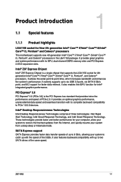
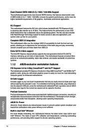
... Chapter 1 Z97-WS 1-1 It natively supports up to six USB 3.0 ports, six SATA 6 Gb/s ports, and M.2 support for New 4th generation Intel® Core™ i7/Intel® Core™ i5/Intel® Core™ i3, Pentium® and Celeron® processors This motherboard supports new ...two SATA drives of up with its GPU, dual-channel DDR3 memory slots and PCI Express 2.0/3.0 expansion slots. Intel® Z97 Express Chipset Intel® Z97 Express Chipset is the PCI Express bus standard that supports the LGA1150 socket for Intel® integrated graphics performance. PCI Express...
... Chapter 1 Z97-WS 1-1 It natively supports up to six USB 3.0 ports, six SATA 6 Gb/s ports, and M.2 support for New 4th generation Intel® Core™ i7/Intel® Core™ i5/Intel® Core™ i3, Pentium® and Celeron® processors This motherboard supports new ...two SATA drives of up with its GPU, dual-channel DDR3 memory slots and PCI Express 2.0/3.0 expansion slots. Intel® Z97 Express Chipset Intel® Z97 Express Chipset is the PCI Express bus standard that supports the LGA1150 socket for Intel® integrated graphics performance. PCI Express...
User Guide
Page 18
...(Solid State Drive) that is behaving abnormally, plug a flash drive into the adjacent USB port, press the motherboard's dedicated Flash Log button and all ASUS Q-Code event logs for enhanced entertainment. ProCool Connector ProCool eliminates the hollow areas associated with traditional power connectors, ... the M.2 slot, which shares bandwidth with this motherboard features the latest server class built-in dual Intel® Ethernet. Extra SATA 6 Gb/s support The Intel Z97 Express chpset natively supports the next-generation Serial ATA (SATA) interface, delivering up to ten times faster ...
...(Solid State Drive) that is behaving abnormally, plug a flash drive into the adjacent USB port, press the motherboard's dedicated Flash Log button and all ASUS Q-Code event logs for enhanced entertainment. ProCool Connector ProCool eliminates the hollow areas associated with traditional power connectors, ... the M.2 slot, which shares bandwidth with this motherboard features the latest server class built-in dual Intel® Ethernet. Extra SATA 6 Gb/s support The Intel Z97 Express chpset natively supports the next-generation Serial ATA (SATA) interface, delivering up to ten times faster ...
User Guide
Page 19
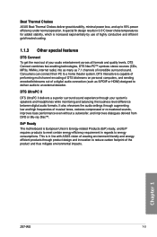
... of a digital audio connection (such as S/PDIF or HDMI) designed to deliver audio to a home theater system. ErP Ready The motherboard is European Union's Energy-related Products (ErP) ready, and ErP requires products to meet certain energy efficiency requirement in regards to 93%... even without a subwoofer, and improves dialogues derived from DVD or Blu-ray Disc™. Chapter 1 Z97-WS 1-3 A special fin design results in line with ASUS vision of creating environment-friendly and energyefficient products through augmenting low and high frequencies of the product and thus...
... of a digital audio connection (such as S/PDIF or HDMI) designed to deliver audio to a home theater system. ErP Ready The motherboard is European Union's Energy-related Products (ErP) ready, and ErP requires products to meet certain energy efficiency requirement in regards to 93%... even without a subwoofer, and improves dialogues derived from DVD or Blu-ray Disc™. Chapter 1 Z97-WS 1-3 A special fin design results in line with ASUS vision of creating environment-friendly and energyefficient products through augmenting low and high frequencies of the product and thus...
User Guide
Page 20
... touching the ICs on them due to static electricity. • Hold components by the edges to the motherboard, peripherals, or components. Chapter 1 1-4 Chapter 1: Product introduction 1.2 Motherboard overview 1.2.1 Before you proceed Take note of the following precautions before you install or remove any component. ... it on a grounded antistatic pad or in the bag that came with the component. • Before you install motherboard components or change any motherboard settings. • Unplug the power cord from the wall socket before touching any component, ensure that the ATX power...
... touching the ICs on them due to static electricity. • Hold components by the edges to the motherboard, peripherals, or components. Chapter 1 1-4 Chapter 1: Product introduction 1.2 Motherboard overview 1.2.1 Before you proceed Take note of the following precautions before you install or remove any component. ... it on a grounded antistatic pad or in the bag that came with the component. • Before you install motherboard components or change any motherboard settings. • Unplug the power cord from the wall socket before touching any component, ensure that the ATX power...
User Guide
Page 21
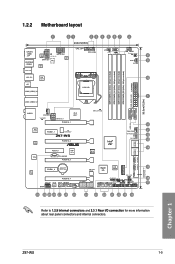
Chapter 1 Z97-WS 1-5 1.2.2 Motherboard layout SPDIFO _HDMI _DP ESATA6G _USB56 BIOS_FLBK 1 21 23 24.4cm(9.6in) ASM 1442K EATX12V1 +12V_PWR LED ASP EATX12V TPU 1257 ASM 1061 CPU_OPT CPU_FAN 4 5 ...) PWR_SUPPLY LED USB3_E12 AUDIO CHA_FAN1 VGA_LED EATX12V_1 PCIEX16_1 PLX 8747 DIAG_CPU LED USB3_34 WGI 210AT WGI 218LM TPU PCIEX1_1 ICS 9DB433AGLF Z97-WS PCIEX16_2 PCIEX4_1 ASM 1187e TB_HEADER PCIEX16_3 Intel® Z97 CHA_FAN3 DR.Power LED DR_POWER SATA6G_1 SATA6G_2 BIOS SATA6G_3 SATA6G_4 M.2(SOCKET3) ALC 1150 PCIEX1_2 Lithium Cell CMOS Power VIA 1394 6315N...
Chapter 1 Z97-WS 1-5 1.2.2 Motherboard layout SPDIFO _HDMI _DP ESATA6G _USB56 BIOS_FLBK 1 21 23 24.4cm(9.6in) ASM 1442K EATX12V1 +12V_PWR LED ASP EATX12V TPU 1257 ASM 1061 CPU_OPT CPU_FAN 4 5 ...) PWR_SUPPLY LED USB3_E12 AUDIO CHA_FAN1 VGA_LED EATX12V_1 PCIEX16_1 PLX 8747 DIAG_CPU LED USB3_34 WGI 210AT WGI 218LM TPU PCIEX1_1 ICS 9DB433AGLF Z97-WS PCIEX16_2 PCIEX4_1 ASM 1187e TB_HEADER PCIEX16_3 Intel® Z97 CHA_FAN3 DR.Power LED DR_POWER SATA6G_1 SATA6G_2 BIOS SATA6G_3 SATA6G_4 M.2(SOCKET3) ALC 1150 PCIEX1_2 Lithium Cell CMOS Power VIA 1394 6315N...
User Guide
Page 23
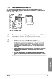
... the PnP cap is shipment/ transit-related. • Keep the cap after installing the motherboard. Chapter 1 Z97-WS 1-7 ASUS will process Return Merchandise Authorization (RMA) requests only if the motherboard comes with a surface mount LGA1150 socket designed for the 4th Generation and the New 4th Generation... socket only. 1.2.3 Central Processing Unit (CPU) The motherboard comes with the cap on the LGA1150 socket. • The product warranty does not cover damage to the PnP cap/socket contacts/motherboard components. Z97-WS Z97-WS CPU LGA1150 Ensure that the PnP cap is on the...
... the PnP cap is shipment/ transit-related. • Keep the cap after installing the motherboard. Chapter 1 Z97-WS 1-7 ASUS will process Return Merchandise Authorization (RMA) requests only if the motherboard comes with a surface mount LGA1150 socket designed for the 4th Generation and the New 4th Generation... socket only. 1.2.3 Central Processing Unit (CPU) The motherboard comes with the cap on the LGA1150 socket. • The product warranty does not cover damage to the PnP cap/socket contacts/motherboard components. Z97-WS Z97-WS CPU LGA1150 Ensure that the PnP cap is on the...

User Guide
Page 24
DIMM_A1 DIMM_A2 DIMM_B1 DIMM_B2 1.2.4 System memory The motherboard comes with eight DDR 3 (Double Data Rate 3) Dual Inline Memory Modules (DIMM) slots. DO NOT install a DDR or DDR2 memory module to the DDR3 slot. A DDR3 module is notched differently from a DDR or DDR2 module. Z97-WS Z97-WS 240-pin DDR3 DIMM sockets Recommended memory configurations Chapter 1 1-8 Chapter 1: Product introduction
DIMM_A1 DIMM_A2 DIMM_B1 DIMM_B2 1.2.4 System memory The motherboard comes with eight DDR 3 (Double Data Rate 3) Dual Inline Memory Modules (DIMM) slots. DO NOT install a DDR or DDR2 memory module to the DDR3 slot. A DDR3 module is notched differently from a DDR or DDR2 module. Z97-WS Z97-WS 240-pin DDR3 DIMM sockets Recommended memory configurations Chapter 1 1-8 Chapter 1: Product introduction

User Guide
Page 25
...'s capabilities and other installed devices. • Always install the DIMMS with the vendor to get the correct memory modules. • Visit the ASUS website for manual memory frequency adjustment. • For system stability, use of memory, we recommend that you do any of the following: a)...the loaded XMP profile is dependent on the motherboard. Memory configurations You may install 2 GB, 4 GB and 8 GB unbuffered and non‑ECC DDR3 DIMMs into the DIMM sockets. • You may operate at http://support.microsoft. Chapter 1 Z97-WS 1-9 Under the default state, some memory ...
...'s capabilities and other installed devices. • Always install the DIMMS with the vendor to get the correct memory modules. • Visit the ASUS website for manual memory frequency adjustment. • For system stability, use of memory, we recommend that you do any of the following: a)...the loaded XMP profile is dependent on the motherboard. Memory configurations You may install 2 GB, 4 GB and 8 GB unbuffered and non‑ECC DDR3 DIMMs into the DIMM sockets. • You may operate at http://support.microsoft. Chapter 1 Z97-WS 1-9 Under the default state, some memory ...
User Guide
Page 26
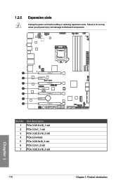
1.2.5 Expansion slots Unplug the power cord before adding or removing expansion cards. Failure to do so may cause you physical injury and damage motherboard components. PCIEX16_1 PCIEX1_1 Z97-WS PCIEX16_2 PCIEX4_1 PCIEX16_3 PCIEX1_2 PCIEX16_4 Slot No. 1 2 3 4 5 6 7 Slot Description PCIe 3.0/2.0 x16_1 slot PCIe 2.0 x1_1 slot PCIe 3.0/2.0 x16_2 slot PCIe 2.0 x4 slot PCIe 3.0/2.0x16_3 slot PCIe 2.0 x1_2 slot PCIe 3.0/2.0 x16_4 slot 1-10 Chapter 1: Product introduction Chapter 1
1.2.5 Expansion slots Unplug the power cord before adding or removing expansion cards. Failure to do so may cause you physical injury and damage motherboard components. PCIEX16_1 PCIEX1_1 Z97-WS PCIEX16_2 PCIEX4_1 PCIEX16_3 PCIEX1_2 PCIEX16_4 Slot No. 1 2 3 4 5 6 7 Slot Description PCIe 3.0/2.0 x16_1 slot PCIe 2.0 x1_1 slot PCIe 3.0/2.0 x16_2 slot PCIe 2.0 x4 slot PCIe 3.0/2.0x16_3 slot PCIe 2.0 x1_2 slot PCIe 3.0/2.0 x16_4 slot 1-10 Chapter 1: Product introduction Chapter 1
User Guide
Page 27
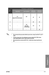
...™ or SLI™ mode. • Connect a chassis fan to the motherboard connector labeled CHA_FAN1-4 when using multiple graphics cards for better thermal environment. • We recommend you connect an EATX 12V_1 cable when running CrossFireX and SLI. Chapter 1 Z97-WS 1-11 PCI Express 3.0 operating mode Slot No. Single VGA SLI CrossFireX 3-WAY...
...™ or SLI™ mode. • Connect a chassis fan to the motherboard connector labeled CHA_FAN1-4 when using multiple graphics cards for better thermal environment. • We recommend you connect an EATX 12V_1 cable when running CrossFireX and SLI. Chapter 1 Z97-WS 1-11 PCI Express 3.0 operating mode Slot No. Single VGA SLI CrossFireX 3-WAY...
User Guide
Page 28
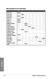
...- shared - - - - - - - - shared - - - - - - shared - - - - - - - - - shared - - - - - shared - - - - - shared - - - - - - - - - Chapter 1 1-12 Chapter 1: Product introduction shared - - - - - - - - shared - - - - - - - - - - - shared - - - - shared - - - - - shared - - - - - - shared - - - - - - shared - - - - - - IRQ assignments for this motherboard PCIe x16_1 PCIe x16_2 PCIe x16_3 PCIe x16_4 PCIe x4_1 PCIe x1_1 PCIe x1_2 SMBUS Controller VIA1394 SATA Controller Intel® LAN1...
...- shared - - - - - - - - shared - - - - - - shared - - - - - - - - - shared - - - - - shared - - - - - shared - - - - - - - - - Chapter 1 1-12 Chapter 1: Product introduction shared - - - - - - - - shared - - - - - - - - - - - shared - - - - shared - - - - - shared - - - - - - shared - - - - - - shared - - - - - - IRQ assignments for this motherboard PCIe x16_1 PCIe x16_2 PCIe x16_3 PCIe x16_4 PCIe x4_1 PCIe x1_1 PCIe x1_2 SMBUS Controller VIA1394 SATA Controller Intel® LAN1...

User Guide
Page 29
Z97-WS PWR_SW Z97-WS Power on a bare or open-case system. This is plugged to reboot the system. Power-on button The motherboard comes with a power-on button that you to fine-tune performance when working on button 2. The button also ... reset button to a power source indicating that allows you to enhance system performance. 1. Z97-WS Z97-WS Reset button RST_SW Chapter 1 Z97-WS 1-13 1.2.6 Onboard buttons and switches Onboard buttons and switches allow you should shut down the system and unplug the power cable before removing or installing any motherboard component.
Z97-WS PWR_SW Z97-WS Power on a bare or open-case system. This is plugged to reboot the system. Power-on button The motherboard comes with a power-on button that you to fine-tune performance when working on button 2. The button also ... reset button to a power source indicating that allows you to enhance system performance. 1. Z97-WS Z97-WS Reset button RST_SW Chapter 1 Z97-WS 1-13 1.2.6 Onboard buttons and switches Onboard buttons and switches allow you should shut down the system and unplug the power cable before removing or installing any motherboard component.
User Guide
Page 30
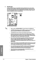
... for the exact location of the DRAM_LED. • The DRAM_LED also lights up due to the latest BIOS version from www.asus.com after using the MemOK! Z97-WS Z97-WS MemOK! Turn off the computer and unplug the power cord for about 30 seconds for the system to section 1.2.8 Onboard LEDs... processes. • Due to boot up when the DIMM is tested. function. 1-14 Chapter 1: Product introduction Chapter 1 Replace the DIMMs with the motherboard may cause system boot failure, and the DRAM_LED near the MemOK! Press and hold the MemOK! If the installed DIMMs still fail to boot and...
... for the exact location of the DRAM_LED. • The DRAM_LED also lights up due to the latest BIOS version from www.asus.com after using the MemOK! Z97-WS Z97-WS MemOK! Turn off the computer and unplug the power cord for about 30 seconds for the system to section 1.2.8 Onboard LEDs... processes. • Due to boot up when the DIMM is tested. function. 1-14 Chapter 1: Product introduction Chapter 1 Replace the DIMMs with the motherboard may cause system boot failure, and the DRAM_LED near the MemOK! Press and hold the MemOK! If the installed DIMMs still fail to boot and...
User Guide
Page 42
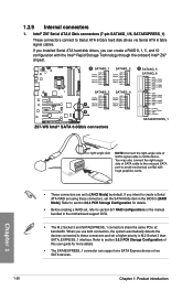
...GND RSATA_RXN2 RSATA_RXP2 GND SATA6G_3 SATA6G_4 GND RSATA_TXP3 RSATA_TXN3 GND A RSATA_RXN3 RSATA_RXP3 GND GND RSATA_TXP4 RSATA_TXN4 GND RSATA_RXN4 RSATA_RXP4 GND B Z97-WS Intel® SATA 6.0Gb/s connectors B SATA6G_5 SATA6G_6 GND RSATA_TXP5 RSATA_TXN5 GND RSATA_RXN5 RSATA_RXP5 GND GND RSATA_TXP6 RSATA_TXN6 GND RSATA_RXN6 ...Before creating a RAID set the SATA Mode item in the BIOS to section 5.1 RAID configurations or the manual bundled in the motherboard support DVD. • The M.2 Socket 3 and SATAEXPRESS_1 connectors share the same PCIe x2 bandwidth. If you can support one ...
...GND RSATA_RXN2 RSATA_RXP2 GND SATA6G_3 SATA6G_4 GND RSATA_TXP3 RSATA_TXN3 GND A RSATA_RXN3 RSATA_RXP3 GND GND RSATA_TXP4 RSATA_TXN4 GND RSATA_RXN4 RSATA_RXP4 GND B Z97-WS Intel® SATA 6.0Gb/s connectors B SATA6G_5 SATA6G_6 GND RSATA_TXP5 RSATA_TXN5 GND RSATA_RXN5 RSATA_RXP5 GND GND RSATA_TXP6 RSATA_TXN6 GND RSATA_RXN6 ...Before creating a RAID set the SATA Mode item in the BIOS to section 5.1 RAID configurations or the manual bundled in the motherboard support DVD. • The M.2 Socket 3 and SATAEXPRESS_1 connectors share the same PCIe x2 bandwidth. If you can support one ...


