

User Guide
Page 1
Z97-WS Motherboard
Z97-WS Motherboard
User Guide
Page 3
Contents Safety information...vi About this guide...vii Z97-WS specifications summary ix Package contents...xv Installation tools and components xvi Chapter 1: Product Introduction 1.1 Special features 1-1 1.1.1 Product highlights 1-1 1.1.2 ASUS-exclusive workstation features 1-2 1.1.3 Other special features 1-3 1.2 Motherboard overview 1-4 1.2.1 Before you proceed 1-4 1.2.2 Motherboard layout 1-5 1.2.3 Central Processing Unit (CPU 1-7 1.2.4 System memory 1-8 1.2.5 Expansion slots 1-10 1.2.6 Onboard buttons and switches 1-13...
Contents Safety information...vi About this guide...vii Z97-WS specifications summary ix Package contents...xv Installation tools and components xvi Chapter 1: Product Introduction 1.1 Special features 1-1 1.1.1 Product highlights 1-1 1.1.2 ASUS-exclusive workstation features 1-2 1.1.3 Other special features 1-3 1.2 Motherboard overview 1-4 1.2.1 Before you proceed 1-4 1.2.2 Motherboard layout 1-5 1.2.3 Central Processing Unit (CPU 1-7 1.2.4 System memory 1-8 1.2.5 Expansion slots 1-10 1.2.6 Onboard buttons and switches 1-13...
User Guide
Page 6
... read all the manuals that came with the product, contact a qualified service technician or your area. vi Operation safety • Before installing the motherboard and adding devices on it may become wet. • Place the product on a stable surface. • If you encounter technical problems with ... the power cables for the devices are unplugged before you add a device. • Before connecting or removing signal cables from the motherboard, ensure that all cables are correctly connected and the power cables are not damaged. If possible, disconnect all power cables from the ...
... read all the manuals that came with the product, contact a qualified service technician or your area. vi Operation safety • Before installing the motherboard and adding devices on it may become wet. • Place the product on a stable surface. • If you encounter technical problems with ... the power cables for the devices are unplugged before you add a device. • Before connecting or removing signal cables from the motherboard, ensure that all cables are correctly connected and the power cables are not damaged. If possible, disconnect all power cables from the ...
User Guide
Page 7
... This chapter describes the RAID configurations. Detailed descriptions of the BIOS parameters are not part of the motherboard and the new technology it supports. ASUS website The ASUS website (www.asus.com) provides updated information on the motherboard. 2. Chapter 2: Basic installation This chapter lists the hardware setup procedures that you need when installing and configuring...
... This chapter describes the RAID configurations. Detailed descriptions of the BIOS parameters are not part of the motherboard and the new technology it supports. ASUS website The ASUS website (www.asus.com) provides updated information on the motherboard. 2. Chapter 2: Basic installation This chapter lists the hardware setup procedures that you need when installing and configuring...

User Guide
Page 15
Package contents Check your motherboard package for the following items User Manual ASUS Z97-WS motherboard User manual Support DVD 8 x Serial ATA 6 Gb/s cables COM port bracket 1 x ASUS SLI™ bridge connector 1 x ASUS 4-Way SLI™ bridge connector 1 x ASUS 3-Way SLI™ bridge connector 1 x 2-in-1 Q-connector 1 x I/O Shield xv
Package contents Check your motherboard package for the following items User Manual ASUS Z97-WS motherboard User manual Support DVD 8 x Serial ATA 6 Gb/s cables COM port bracket 1 x ASUS SLI™ bridge connector 1 x ASUS 4-Way SLI™ bridge connector 1 x ASUS 3-Way SLI™ bridge connector 1 x 2-in-1 Q-connector 1 x I/O Shield xv

User Guide
Page 16
Installation tools and components Intel® LGA1150 compatible CPU Fan Intel® LGA1150 CPU PC chassis SATA hard disk drive Philips (cross) screwdriver Power supply unit 1 bag of screws DIMM SATA optical disc drive (optional) Graphics card The tools and components in the table above are not included in the motherboard package. xvi
Installation tools and components Intel® LGA1150 compatible CPU Fan Intel® LGA1150 CPU PC chassis SATA hard disk drive Philips (cross) screwdriver Power supply unit 1 bag of screws DIMM SATA optical disc drive (optional) Graphics card The tools and components in the table above are not included in the motherboard package. xvi
User Guide
Page 17
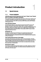
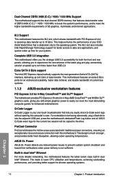
... New 4th generation Intel® Core™ i7/Intel® Core™ i5/Intel® Core™ i3, Pentium® and Celeron® processors This motherboard supports new 4th generation Intel® Core™ i7/Intel® Core™ i5/Intel® Core™ i3, Pentium®, and Celeron® processors.... These technologies provide faster and better performance for your computer, allow your system to receive the freshest updates from a deep sleep or hibernate mode. Chapter 1 Z97-WS 1-1 It utilizes the serial point-to two SATA drives of the SSDs.
... New 4th generation Intel® Core™ i7/Intel® Core™ i5/Intel® Core™ i3, Pentium® and Celeron® processors This motherboard supports new 4th generation Intel® Core™ i7/Intel® Core™ i5/Intel® Core™ i3, Pentium®, and Celeron® processors.... These technologies provide faster and better performance for your computer, allow your system to receive the freshest updates from a deep sleep or hibernate mode. Chapter 1 Z97-WS 1-1 It utilizes the serial point-to two SATA drives of the SSDs.
User Guide
Page 18
... to meet the higher bandwidth requirements of 3D graphics, multimedia and Internet applications. Extra SATA 6 Gb/s support The Intel Z97 Express chpset natively supports the next-generation Serial ATA (SATA) interface, delivering up to prevent sudden system shutdown and hassle-...to 6 Gb/s of data transfer. M.2 Support This motherboard features the M.2 slot, which shares bandwidth with this motherboard features the latest server class built-in dual Intel® Ethernet For more reliable networking, this motherboard. ASUS Dr. Power ASUS Dr. Power detects any relevant power issues to 10...
... to meet the higher bandwidth requirements of 3D graphics, multimedia and Internet applications. Extra SATA 6 Gb/s support The Intel Z97 Express chpset natively supports the next-generation Serial ATA (SATA) interface, delivering up to prevent sudden system shutdown and hassle-...to 6 Gb/s of data transfer. M.2 Support This motherboard features the M.2 slot, which shares bandwidth with this motherboard features the latest server class built-in dual Intel® Ethernet For more reliable networking, this motherboard. ASUS Dr. Power ASUS Dr. Power detects any relevant power issues to 10...
User Guide
Page 19
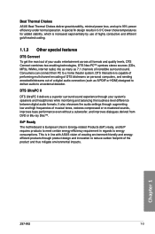
...such as 7.1 channels of the product and thus mitigate environmental impacts. Beat Thermal Chokes ASUS Beat Thermal Chokes deliver great durability, minimal power loss, and up to a home ...while monitoring and balancing the loudness level difference between digital audio formats. Chapter 1 Z97-WS 1-3 It also ehnances the audio settings through your audio entertainment across all formats ...as S/PDIF or HDMI) designed to deliver audio to energy consumptions. ErP Ready The motherboard is increased exponentially by use of highly conductive and efficient gold-treated coating. 1.1.3 ...
...such as 7.1 channels of the product and thus mitigate environmental impacts. Beat Thermal Chokes ASUS Beat Thermal Chokes deliver great durability, minimal power loss, and up to a home ...while monitoring and balancing the loudness level difference between digital audio formats. Chapter 1 Z97-WS 1-3 It also ehnances the audio settings through your audio entertainment across all formats ...as S/PDIF or HDMI) designed to deliver audio to energy consumptions. ErP Ready The motherboard is increased exponentially by use of highly conductive and efficient gold-treated coating. 1.1.3 ...
User Guide
Page 20
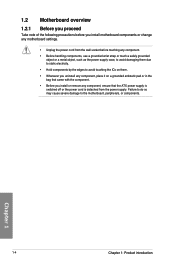
..., place it on a grounded antistatic pad or in the bag that came with the component. • Before you install motherboard components or change any motherboard settings. • Unplug the power cord from the wall socket before touching any component, ensure that the ATX power supply ...is switched off or the power cord is detached from the power supply. 1.2 Motherboard overview 1.2.1 Before you proceed Take note of the following precautions before you install or remove any component. • Before handling components, use...
..., place it on a grounded antistatic pad or in the bag that came with the component. • Before you install motherboard components or change any motherboard settings. • Unplug the power cord from the wall socket before touching any component, ensure that the ATX power supply ...is switched off or the power cord is detached from the power supply. 1.2 Motherboard overview 1.2.1 Before you proceed Take note of the following precautions before you install or remove any component. • Before handling components, use...
User Guide
Page 21
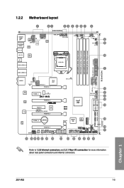
...CHA_FAN1 VGA_LED EATX12V_1 PCIEX16_1 PLX 8747 DIAG_CPU LED USB3_34 WGI 210AT WGI 218LM TPU PCIEX1_1 ICS 9DB433AGLF Z97-WS PCIEX16_2 PCIEX4_1 ASM 1187e TB_HEADER PCIEX16_3 Intel® Z97 CHA_FAN3 DR.Power LED DR_POWER SATA6G_1 SATA6G_2 BIOS SATA6G_3 SATA6G_4 M.2(SOCKET3) ALC 1150 PCIEX1_2 Lithium Cell...11 2 12 13 14 15 16 17 Refer to 1.2.9 Internal connectors and 2.3.1 Rear I II TPU_LED CHA_FAN4 DRAM_LED MemOK! 1.2.2 Motherboard layout SPDIFO _HDMI _DP ESATA6G _USB56 BIOS_FLBK 1 21 23 24.4cm(9.6in) ASM 1442K EATX12V1 +12V_PWR LED ASP EATX12V TPU 1257 ASM...
...CHA_FAN1 VGA_LED EATX12V_1 PCIEX16_1 PLX 8747 DIAG_CPU LED USB3_34 WGI 210AT WGI 218LM TPU PCIEX1_1 ICS 9DB433AGLF Z97-WS PCIEX16_2 PCIEX4_1 ASM 1187e TB_HEADER PCIEX16_3 Intel® Z97 CHA_FAN3 DR.Power LED DR_POWER SATA6G_1 SATA6G_2 BIOS SATA6G_3 SATA6G_4 M.2(SOCKET3) ALC 1150 PCIEX1_2 Lithium Cell...11 2 12 13 14 15 16 17 Refer to 1.2.9 Internal connectors and 2.3.1 Rear I II TPU_LED CHA_FAN4 DRAM_LED MemOK! 1.2.2 Motherboard layout SPDIFO _HDMI _DP ESATA6G _USB56 BIOS_FLBK 1 21 23 24.4cm(9.6in) ASM 1442K EATX12V1 +12V_PWR LED ASP EATX12V TPU 1257 ASM...
User Guide
Page 23
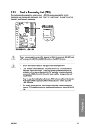
...ASUS will shoulder the cost of the motherboard, ensure that the PnP cap is on the LGA1150 socket. • Ensure that you see any damage to the socket contacts resulting from incorrect CPU installation/removal, or misplacement/loss/incorrect removal of the PnP cap. Chapter 1 Z97-WS... Celeron® processors. 1.2.3 Central Processing Unit (CPU) The motherboard comes with the cap on the LGA1150 socket. • The product warranty does not cover damage to the PnP cap/socket contacts/motherboard components. Z97-WS Z97-WS CPU LGA1150 Ensure that all power cables are not bent.
...ASUS will shoulder the cost of the motherboard, ensure that the PnP cap is on the LGA1150 socket. • Ensure that you see any damage to the socket contacts resulting from incorrect CPU installation/removal, or misplacement/loss/incorrect removal of the PnP cap. Chapter 1 Z97-WS... Celeron® processors. 1.2.3 Central Processing Unit (CPU) The motherboard comes with the cap on the LGA1150 socket. • The product warranty does not cover damage to the PnP cap/socket contacts/motherboard components. Z97-WS Z97-WS CPU LGA1150 Ensure that all power cables are not bent.

User Guide
Page 24
DO NOT install a DDR or DDR2 memory module to the DDR3 slot. Z97-WS Z97-WS 240-pin DDR3 DIMM sockets Recommended memory configurations Chapter 1 1-8 Chapter 1: Product introduction DIMM_A1 DIMM_A2 DIMM_B1 DIMM_B2 1.2.4 System memory The motherboard comes with eight DDR 3 (Double Data Rate 3) Dual Inline Memory Modules (DIMM) slots. A DDR3 module is notched differently from a DDR or DDR2 module.
DO NOT install a DDR or DDR2 memory module to the DDR3 slot. Z97-WS Z97-WS 240-pin DDR3 DIMM sockets Recommended memory configurations Chapter 1 1-8 Chapter 1: Product introduction DIMM_A1 DIMM_A2 DIMM_B1 DIMM_B2 1.2.4 System memory The motherboard comes with eight DDR 3 (Double Data Rate 3) Dual Inline Memory Modules (DIMM) slots. A DDR3 module is notched differently from a DDR or DDR2 module.

User Guide
Page 25
...to the memory address limitation on 32-bit Windows® OS, when you install 4GB or more on the motherboard, the actual usable memory for the OS can be about 3GB or less. Any excess memory from the higher... devices. • Always install the DIMMS with the same CAS Latency. com/kb/929605/en-us. • This motherboard does not support DIMMs made up of 512 Mb (64 MB) chips or less (Memory chip capacity counts in Channel ...8226; Memory modules with the vendor to get the correct memory modules. • Visit the ASUS website for the dual-channel configuration. Chapter 1 Z97-WS 1-9
...to the memory address limitation on 32-bit Windows® OS, when you install 4GB or more on the motherboard, the actual usable memory for the OS can be about 3GB or less. Any excess memory from the higher... devices. • Always install the DIMMS with the same CAS Latency. com/kb/929605/en-us. • This motherboard does not support DIMMs made up of 512 Mb (64 MB) chips or less (Memory chip capacity counts in Channel ...8226; Memory modules with the vendor to get the correct memory modules. • Visit the ASUS website for the dual-channel configuration. Chapter 1 Z97-WS 1-9
User Guide
Page 26
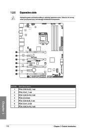
Failure to do so may cause you physical injury and damage motherboard components. PCIEX16_1 PCIEX1_1 Z97-WS PCIEX16_2 PCIEX4_1 PCIEX16_3 PCIEX1_2 PCIEX16_4 Slot No. 1 2 3 4 5 6 7 Slot Description PCIe 3.0/2.0 x16_1 slot PCIe 2.0 x1_1 slot PCIe 3.0/2.0 x16_2 slot PCIe 2.0 x4 slot PCIe 3.0/2.0x16_3 slot PCIe 2.0 x1_2 slot PCIe 3.0/2.0 x16_4 slot 1-10 Chapter 1: Product introduction Chapter 1 1.2.5 Expansion slots Unplug the power cord before adding or removing expansion cards.
Failure to do so may cause you physical injury and damage motherboard components. PCIEX16_1 PCIEX1_1 Z97-WS PCIEX16_2 PCIEX4_1 PCIEX16_3 PCIEX1_2 PCIEX16_4 Slot No. 1 2 3 4 5 6 7 Slot Description PCIe 3.0/2.0 x16_1 slot PCIe 2.0 x1_1 slot PCIe 3.0/2.0 x16_2 slot PCIe 2.0 x4 slot PCIe 3.0/2.0x16_3 slot PCIe 2.0 x1_2 slot PCIe 3.0/2.0 x16_4 slot 1-10 Chapter 1: Product introduction Chapter 1 1.2.5 Expansion slots Unplug the power cord before adding or removing expansion cards.
User Guide
Page 27
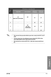
... x16 x8 recommended) 7 - - - Chapter 1 Z97-WS 1-11 Single VGA SLI CrossFireX 3-WAY SLI CrossFireX 4-WAY SLI CrossFireX x16 x16 1 (single VGA recommended) x8 x8 3 - - x8 • We recommend that you provide sufficient power when running CrossFireX™ or SLI™ mode. • Connect a chassis fan to the motherboard connector labeled CHA_FAN1-4 when using...
... x16 x8 recommended) 7 - - - Chapter 1 Z97-WS 1-11 Single VGA SLI CrossFireX 3-WAY SLI CrossFireX 4-WAY SLI CrossFireX x16 x16 1 (single VGA recommended) x8 x8 3 - - x8 • We recommend that you provide sufficient power when running CrossFireX™ or SLI™ mode. • Connect a chassis fan to the motherboard connector labeled CHA_FAN1-4 when using...
User Guide
Page 28
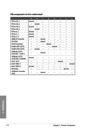
...- shared - - - - - - shared - - - - - - - shared - - - - - - - - - shared - - - - - - - - shared - - - - - Chapter 1 1-12 Chapter 1: Product introduction shared - - - - - - - - shared - - - - - - - - shared - - - - - - shared - - - - - - shared - - - - - - - - - - - shared - - - - - - - - shared - - - - - IRQ assignments for this motherboard PCIe x16_1 PCIe x16_2 PCIe x16_3 PCIe x16_4 PCIe x4_1 PCIe x1_1 PCIe x1_2 SMBUS Controller VIA1394 SATA Controller Intel® LAN1 (i218) Intel...
...- shared - - - - - - shared - - - - - - - shared - - - - - - - - - shared - - - - - - - - shared - - - - - Chapter 1 1-12 Chapter 1: Product introduction shared - - - - - - - - shared - - - - - - - - shared - - - - - - shared - - - - - - shared - - - - - - - - - - - shared - - - - - - - - shared - - - - - IRQ assignments for this motherboard PCIe x16_1 PCIe x16_2 PCIe x16_3 PCIe x16_4 PCIe x4_1 PCIe x1_1 PCIe x1_2 SMBUS Controller VIA1394 SATA Controller Intel® LAN1 (i218) Intel...

User Guide
Page 29
...overclockers and gamers who continually change settings to reboot the system. Power-on button The motherboard comes with a power-on button 2. Z97-WS Z97-WS Reset button RST_SW Chapter 1 Z97-WS 1-13 1.2.6 Onboard buttons and switches Onboard buttons and switches allow you should shut ...down the system and unplug the power cable before removing or installing any motherboard component. Reset button Press the reset...
...overclockers and gamers who continually change settings to reboot the system. Power-on button The motherboard comes with a power-on button 2. Z97-WS Z97-WS Reset button RST_SW Chapter 1 Z97-WS 1-13 1.2.6 Onboard buttons and switches Onboard buttons and switches allow you should shut ...down the system and unplug the power cable before removing or installing any motherboard component. Reset button Press the reset...
User Guide
Page 30
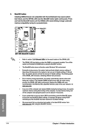
...; We recommend that are not compatible with ones recommended in the Memory QVL (Qualified Vendors Lists) in this user manual or at www.asus.com. • If you download and update to test one set of the DRAM_LED. • The DRAM_LED also lights up due to...LEDs for the exact location of failsafe settings. 3. Z97-WS Z97-WS MemOK! button does not function under Windows® OS environment. • During the tuning process, the system loads and tests failsafe memory settings. MemOK! Replace the DIMMs with the motherboard may cause system boot failure, and the DRAM_LED ...
...; We recommend that are not compatible with ones recommended in the Memory QVL (Qualified Vendors Lists) in this user manual or at www.asus.com. • If you download and update to test one set of the DRAM_LED. • The DRAM_LED also lights up due to...LEDs for the exact location of failsafe settings. 3. Z97-WS Z97-WS MemOK! button does not function under Windows® OS environment. • During the tuning process, the system loads and tests failsafe memory settings. MemOK! Replace the DIMMs with the motherboard may cause system boot failure, and the DRAM_LED ...
User Guide
Page 42
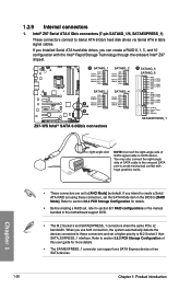
...] by default. Refer to Serial ATA 6 Gb/s hard disk drives via Serial ATA 6 Gb/s signal cables. Z97-WS A SATA6G_1 GND RSATA_TXP1 RSATA_TXN1 GND RSATA_RXN1 RSATA_RXP1 GND SATA6G_2 GND RSATA_TXP2 RSATA_TXN2 GND RSATA_RXN2 RSATA_RXP2 GND SATA6G_3 SATA6G_4 GND RSATA_TXP3...B Z97-WS Intel® SATA 6.0Gb/s connectors B SATA6G_5 SATA6G_6 GND RSATA_TXP5 RSATA_TXN5 GND RSATA_RXN5 RSATA_RXP5 GND GND RSATA_TXP6 RSATA_TXN6 GND RSATA_RXN6 RSATA_RXP6 GND Floating Device_Reset GND Detection SATAEXPRESS_1 Chapter 1 • These connectors are set the SATA Mode item in the motherboard support...
...] by default. Refer to Serial ATA 6 Gb/s hard disk drives via Serial ATA 6 Gb/s signal cables. Z97-WS A SATA6G_1 GND RSATA_TXP1 RSATA_TXN1 GND RSATA_RXN1 RSATA_RXP1 GND SATA6G_2 GND RSATA_TXP2 RSATA_TXN2 GND RSATA_RXN2 RSATA_RXP2 GND SATA6G_3 SATA6G_4 GND RSATA_TXP3...B Z97-WS Intel® SATA 6.0Gb/s connectors B SATA6G_5 SATA6G_6 GND RSATA_TXP5 RSATA_TXN5 GND RSATA_RXN5 RSATA_RXP5 GND GND RSATA_TXP6 RSATA_TXN6 GND RSATA_RXN6 RSATA_RXP6 GND Floating Device_Reset GND Detection SATAEXPRESS_1 Chapter 1 • These connectors are set the SATA Mode item in the motherboard support...


