User Guide
Page 9
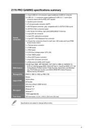
x 9.6 in . ix Z170 PRO GAMING specifications summary Internal connectors BIOS features Manageability Support DVD OS support Form factor 1 x ... X CPU Over Voltage jumper (CPU_OV) 1 x Clear CMOS jumper 1 x 24-pin EATX power connector 1 x 8-pin ATX 12V power connector 1 x ROG extension (ROG_EXT) header 128 Mb Flash ROM, UEFI AMI BIOS, PnP, DMI 3.0, WfM 2.0, SM BIOS... Note, Last Modified Log, F12 PrintScreen function, and ASUS DRAM SPD (Serial Presence Detect) memory information WfM 2.0, DMI 3.0, WOL by PME, PXE Drivers ASUS utilities EZ Update Anti-virus software (OEM version) Windows...
x 9.6 in . ix Z170 PRO GAMING specifications summary Internal connectors BIOS features Manageability Support DVD OS support Form factor 1 x ... X CPU Over Voltage jumper (CPU_OV) 1 x Clear CMOS jumper 1 x 24-pin EATX power connector 1 x 8-pin ATX 12V power connector 1 x ROG extension (ROG_EXT) header 128 Mb Flash ROM, UEFI AMI BIOS, PnP, DMI 3.0, WfM 2.0, SM BIOS... Note, Last Modified Log, F12 PrintScreen function, and ASUS DRAM SPD (Serial Presence Detect) memory information WfM 2.0, DMI 3.0, WOL by PME, PXE Drivers ASUS utilities EZ Update Anti-virus software (OEM version) Windows...
User Guide
Page 11
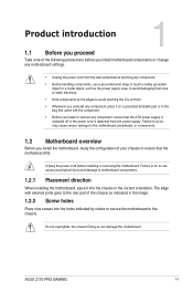
...edges to avoid touching the ICs on them due to static electricity. • Hold components by circles to secure the motherboard to the chassis. ASUS Z170 PRO GAMING 1-1 Unplug the power cord before touching any component, ensure that the motherboard fits. The edge with the component. • Before you install or... install the motherboard, study the configuration of your chassis to do so can damage the motherboard. Failure to ensure that the ATX power supply is switched off or the power cord is detached from the wall socket before installing or removing the motherboard.
...edges to avoid touching the ICs on them due to static electricity. • Hold components by circles to secure the motherboard to the chassis. ASUS Z170 PRO GAMING 1-1 Unplug the power cord before touching any component, ensure that the motherboard fits. The edge with the component. • Before you install or... install the motherboard, study the configuration of your chassis to do so can damage the motherboard. Failure to ensure that the ATX power supply is switched off or the power cord is detached from the wall socket before installing or removing the motherboard.
User Guide
Page 13
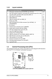
1.2.4 Layout contents Connectors/Jumpers/Slots/LED 1. Model name LEDs 7. Standby Power LED (SB_PWR) 14. Z170 PRO GAMING CPU socket LGA1151 ASUS Z170 PRO GAMING 1-3 USB 3.0 connector (20-1 pin USB3_12) 6. Thermal sensor connector (2-pin T_SENSOR) 10. TPM connector (14-1 pin TPM) 17. SupremeFX...pin USB78, USB910, USB1112) 15. Serial port connectors (10-1 pin COM) 18. M.2 Socket 3 9. Clear RTC RAM (2-pin CLRTC) 13. ATX power connectors (24-pin EATXPWR, 8-pin ATX12V) 2. CPU, CPU optional, extension, and chassis fan connectors (4-pin CPU_FAN, 4-pin CPU_OPT, 5-pin EXT_FAN, 4-pin...
1.2.4 Layout contents Connectors/Jumpers/Slots/LED 1. Model name LEDs 7. Standby Power LED (SB_PWR) 14. Z170 PRO GAMING CPU socket LGA1151 ASUS Z170 PRO GAMING 1-3 USB 3.0 connector (20-1 pin USB3_12) 6. Thermal sensor connector (2-pin T_SENSOR) 10. TPM connector (14-1 pin TPM) 17. SupremeFX...pin USB78, USB910, USB1112) 15. Serial port connectors (10-1 pin COM) 18. M.2 Socket 3 9. Clear RTC RAM (2-pin CLRTC) 13. ATX power connectors (24-pin EATXPWR, 8-pin ATX12V) 2. CPU, CPU optional, extension, and chassis fan connectors (4-pin CPU_FAN, 4-pin CPU_OPT, 5-pin EXT_FAN, 4-pin...
User Guide
Page 32
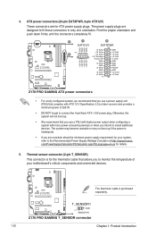
... are designed to the Recommended Power Supply Wattage Calculator at http://support.asus. The system may become unstable or may not boot up . • We recommend that you intend to connect the 4-pin/8-pin ATX +12V power plug. The thermistor cable is for the thermistor cable ... +5 Volts GND +5 Volts GND +3 Volts +3 Volts PIN 1 GND +5 Volts +5 Volts +5 Volts -5 Volts GND GND GND PSON# GND -12 Volts +3 Volts Z170 PRO GAMING ATX power connectors • For a fully configured system, we recommend that you use a power supply unit (PSU) that allows you are for details. 5. 4. Find the ...
... are designed to the Recommended Power Supply Wattage Calculator at http://support.asus. The system may become unstable or may not boot up . • We recommend that you intend to connect the 4-pin/8-pin ATX +12V power plug. The thermistor cable is for the thermistor cable ... +5 Volts GND +5 Volts GND +3 Volts +3 Volts PIN 1 GND +5 Volts +5 Volts +5 Volts -5 Volts GND GND GND PSON# GND -12 Volts +3 Volts Z170 PRO GAMING ATX power connectors • For a fully configured system, we recommend that you use a power supply unit (PSU) that allows you are for details. 5. 4. Find the ...

User Guide
Page 36
...disk drive activity LED (2-pin +HDD_LED-) This 2-pin connector is for the chassis-mounted system warning speaker. RESET +PWR_LED* Requires an ATX power supply Z170 PRO GAMING System panel connector • System power LED (4-pin +PWR_LED-) This 2-pin connector is for system reboot without turning off mode depending ...button for the system power button. PANEL +PWR_LED- Connect the chassis power LED cable to hear system beeps and warnings. • ATX power button/soft-off button (2-pin PWR_SW) This connector is for the HDD Activity LED. The speaker allows you turn on the...
...disk drive activity LED (2-pin +HDD_LED-) This 2-pin connector is for the chassis-mounted system warning speaker. RESET +PWR_LED* Requires an ATX power supply Z170 PRO GAMING System panel connector • System power LED (4-pin +PWR_LED-) This 2-pin connector is for system reboot without turning off mode depending ...button for the system power button. PANEL +PWR_LED- Connect the chassis power LED cable to hear system beeps and warnings. • ATX power button/soft-off button (2-pin PWR_SW) This connector is for the HDD Activity LED. The speaker allows you turn on the...
User Guide
Page 75
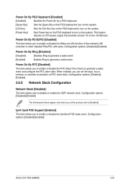
... set the previous item to generate a wake event and configure the RTC alarm date. This feature requires an ATX power supply that provides at least 1A on the +5VSB lead. Configuration options: [Disabled] [Enabled] ASUS Z170 PRO GAMING 2-35 Configuration options: [Disabled] [Enabled] 2.6.9 Network Stack Configuration Network Stack [Disabled] This item allows user to generate...
... set the previous item to generate a wake event and configure the RTC alarm date. This feature requires an ATX power supply that provides at least 1A on the +5VSB lead. Configuration options: [Disabled] [Enabled] ASUS Z170 PRO GAMING 2-35 Configuration options: [Disabled] [Enabled] 2.6.9 Network Stack Configuration Network Stack [Disabled] This item allows user to generate...

