User Guide
Page 16
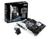
Actual product specifications may vary with different models. xvi Package contents Check your motherboard package for the following items 2 x M.2 screws ASUS Z170-DELUXE Series motherboard 1 x ASUS Q-Shield 6 x Serial ATA 6 Gb/s cables 1 x ASUS SLI™ bridge connector 1 x 2-in-1 ASUS Q-Connector kit 1 x Hyper M.2 X4 Mini Card Support DVD 1 x Hyper Kit 1 x 3T3R dual-band Wi-Fi moving antennas (Wi-Fi...
Actual product specifications may vary with different models. xvi Package contents Check your motherboard package for the following items 2 x M.2 screws ASUS Z170-DELUXE Series motherboard 1 x ASUS Q-Shield 6 x Serial ATA 6 Gb/s cables 1 x ASUS SLI™ bridge connector 1 x 2-in-1 ASUS Q-Connector kit 1 x Hyper M.2 X4 Mini Card Support DVD 1 x Hyper Kit 1 x 3T3R dual-band Wi-Fi moving antennas (Wi-Fi...
User Guide
Page 19
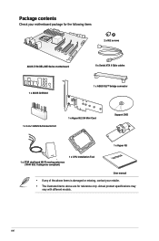
...; processors. It provides great graphics and system performance with its GPU, dual-channel DDR4 memory slots and PCI Express 2.0/3.0 expansion slots. Intel® Z170 Express Chipset Intel® Z170 Express Chipset is the PCI Express bus standard that enables mulit-GPU setup, giving you the full power of the latest graphics technologies... Intel® Core™ i7/Intel® Core™ i5/Intel® Core™ i3, Pentium® , and Celeron® processors in the LGA1151 package. ASUS Z170-DELUXE Series 1-1
...; processors. It provides great graphics and system performance with its GPU, dual-channel DDR4 memory slots and PCI Express 2.0/3.0 expansion slots. Intel® Z170 Express Chipset Intel® Z170 Express Chipset is the PCI Express bus standard that enables mulit-GPU setup, giving you the full power of the latest graphics technologies... Intel® Core™ i7/Intel® Core™ i5/Intel® Core™ i3, Pentium® , and Celeron® processors in the LGA1151 package. ASUS Z170-DELUXE Series 1-1
User Guide
Page 21
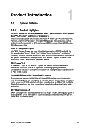
... as the power supply case, to avoid damaging them due to static electricity. • Hold components by the edges to the motherboard, peripherals, or components. ASUS Z170-DELUXE Series 1-3 Chapter 1 1.2 Motherboard overview 1.2.1 Before you proceed Take note of the following precautions before you install or remove any component, ensure that the ATX power...
... as the power supply case, to avoid damaging them due to static electricity. • Hold components by the edges to the motherboard, peripherals, or components. ASUS Z170-DELUXE Series 1-3 Chapter 1 1.2 Motherboard overview 1.2.1 Before you proceed Take note of the following precautions before you install or remove any component, ensure that the ATX power...
User Guide
Page 23
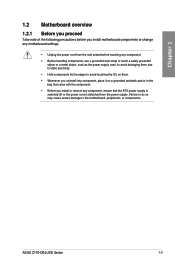
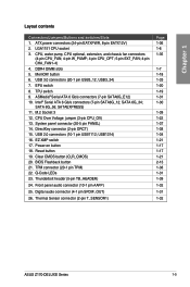
...) Page 1-36 1-6 1-35 1-7 1-18 1-33 1-20 1-19 1-31 1-30 1-39 1-22 1-37 1-38 1-34 1-21 1-17 1-17 1-21 2-13 1-38 1-31 1-39 1-32 1-31 1-32 ASUS Z170-DELUXE Series 1-5 System panel connector (20-5 pin PANEL) 14. USB1314) 16. TPM connector (20-1 pin TPM) 22. Power-on button 18. ATX power connectors (24-pin...
...) Page 1-36 1-6 1-35 1-7 1-18 1-33 1-20 1-19 1-31 1-30 1-39 1-22 1-37 1-38 1-34 1-21 1-17 1-17 1-21 2-13 1-38 1-31 1-39 1-32 1-31 1-32 ASUS Z170-DELUXE Series 1-5 System panel connector (20-5 pin PANEL) 14. USB1314) 16. TPM connector (20-1 pin TPM) 22. Power-on button 18. ATX power connectors (24-pin...

User Guide
Page 25
DO NOT install a DDR, DDR2, or DDR3 memory module to the DDR4 slot. Chapter 1 1.2.4 System memory The motherboard comes with four Double Data Rate 4 (DDR4) Dual Inline Memory Modules (DIMM) slots. A DDR4 module is notched differently from a DDR, DDR2, or DDR3 module. Recommended memory configurations ASUS Z170-DELUXE Series 1-7
DO NOT install a DDR, DDR2, or DDR3 memory module to the DDR4 slot. Chapter 1 1.2.4 System memory The motherboard comes with four Double Data Rate 4 (DDR4) Dual Inline Memory Modules (DIMM) slots. A DDR4 module is notched differently from a DDR, DDR2, or DDR3 module. Recommended memory configurations ASUS Z170-DELUXE Series 1-7

User Guide
Page 27
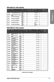
... • 1.35V • 1.35V • 1.35V • 1.35V • 1.35V • 1.35V • 1.35V • 1.35V • ASUS Z170-DELUXE Series 1-9 Timing Voltage SS Samsung K4A4G085WD 16-18-18-38 1.35V DIMM socket support (Optional) 1 24 • DDR4 3333 (O.C.) MHz capability Vendors Part No. ...16GB(4GB*4) SS PUD43200C164G4NJW 16GB(4GB*4) SS SK hynix SK hynix SK hynix SK hynix Chip NO. Chapter 1 Z170-DELUXE Motherboard Qualified Vendors Lists (QVL) DDR4 3466 (O.C.) MHz capability Vendors Part No. Size CORSAIR CMD16GX4M4B3400C16 16GB(4GB*4) SS/DS ...
... • 1.35V • 1.35V • 1.35V • 1.35V • 1.35V • 1.35V • 1.35V • 1.35V • ASUS Z170-DELUXE Series 1-9 Timing Voltage SS Samsung K4A4G085WD 16-18-18-38 1.35V DIMM socket support (Optional) 1 24 • DDR4 3333 (O.C.) MHz capability Vendors Part No. ...16GB(4GB*4) SS PUD43200C164G4NJW 16GB(4GB*4) SS SK hynix SK hynix SK hynix SK hynix Chip NO. Chapter 1 Z170-DELUXE Motherboard Qualified Vendors Lists (QVL) DDR4 3466 (O.C.) MHz capability Vendors Part No. Size CORSAIR CMD16GX4M4B3400C16 16GB(4GB*4) SS/DS ...
User Guide
Page 29
...-15-15-35 1.2 ••• 15-15-15-35 1.2 ••• 16-16-16-36 1.2 ••• (continued on the next page) ASUS Z170-DELUXE Series 1-11 SS - - 14-15-15- 1.35 • • • 40-2 - 2800-16-18- 1.25 • • • 18-36 DDR4 2666 (O.C.) MHz capability Vendors...
...-15-15-35 1.2 ••• 15-15-15-35 1.2 ••• 16-16-16-36 1.2 ••• (continued on the next page) ASUS Z170-DELUXE Series 1-11 SS - - 14-15-15- 1.35 • • • 40-2 - 2800-16-18- 1.25 • • • 18-36 DDR4 2666 (O.C.) MHz capability Vendors...

User Guide
Page 31
...; 15-15-15-36 1.2 2133-15-15- 15-37 2133-15-15- 15-37 15-15-15-36 - 15-15-15-36 - ••• ASUS Z170-DELUXE Series 1-13
...; 15-15-15-36 1.2 2133-15-15- 15-37 2133-15-15- 15-37 15-15-15-36 - 15-15-15-36 - ••• ASUS Z170-DELUXE Series 1-13

User Guide
Page 33
Failure to do so may cause you physical injury and damage motherboard components. 1.2.5 Expansion slots Unplug the power cord before adding or removing expansion cards. Chapter 1 Slot No. 1 2 3 4 5 6 7 Slot Description PCIE 2.0 x1_1 slot PCIE 3.0/2.0 x16_1 slot PCIE 2.0 x1_2 slot PCIE 2.0 x1_3 slot PCIE 3.0/2.0 x16_2 slot PCIE 2.0 x1_4 slot PCIE 3.0/2.0 x16_3 slot ASUS Z170-DELUXE Series 1-15
Failure to do so may cause you physical injury and damage motherboard components. 1.2.5 Expansion slots Unplug the power cord before adding or removing expansion cards. Chapter 1 Slot No. 1 2 3 4 5 6 7 Slot Description PCIE 2.0 x1_1 slot PCIE 3.0/2.0 x16_1 slot PCIE 2.0 x1_2 slot PCIE 2.0 x1_3 slot PCIE 3.0/2.0 x16_2 slot PCIE 2.0 x1_4 slot PCIE 3.0/2.0 x16_3 slot ASUS Z170-DELUXE Series 1-15

User Guide
Page 35
... overclockers and gamers who continually change settings to enhance system performance. 1. This is plugged to a power source indicating that allows you to reboot the system. ASUS Z170-DELUXE Series 1-17 The button also lights up the system. Power-on button The motherboard comes with a power-on button that you should shut down the...
... overclockers and gamers who continually change settings to enhance system performance. 1. This is plugged to a power source indicating that allows you to reboot the system. ASUS Z170-DELUXE Series 1-17 The button also lights up the system. Power-on button The motherboard comes with a power-on button that you should shut down the...

User Guide
Page 37
However, the system will be activated after the next system bootup. • You may use the last setting you have made. ASUS Z170-DELUXE Series 1-19 TPU switch With its two-level adjustment functions, the TPU allows you enable this switch under Windows® OS environment, the TPU function ...
However, the system will be activated after the next system bootup. • You may use the last setting you have made. ASUS Z170-DELUXE Series 1-19 TPU switch With its two-level adjustment functions, the TPU allows you enable this switch under Windows® OS environment, the TPU function ...
User Guide
Page 39
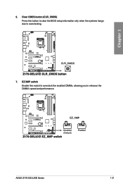
Chapter 1 6. Clear CMOS button (CLR_CMOS) Press this switch to overclock the installed DIMMs, allowing you to overclocking. 7. EZ XMP switch Enable this button to clear the BIOS setup information only when the systems hangs due to enhance the DIMM's speed and performance. ASUS Z170-DELUXE Series 1-21
Chapter 1 6. Clear CMOS button (CLR_CMOS) Press this switch to overclock the installed DIMMs, allowing you to overclocking. 7. EZ XMP switch Enable this button to clear the BIOS setup information only when the systems hangs due to enhance the DIMM's speed and performance. ASUS Z170-DELUXE Series 1-21

User Guide
Page 41
Chapter 1 1.2.8 Onboard LEDs 1. TPU LED (TPU_LED) The TPU LED lights up until the problem is enabled. If an error is found, the critical component's LED stays lit up when the TPU switch is solved. 2. ASUS Z170-DELUXE Series 1-23 POST State LEDs The POST State LEDs provide the status of these key components during POST (Power-On-Self Test): CPU, memory modules, VGA card, and hard disk drives.
Chapter 1 1.2.8 Onboard LEDs 1. TPU LED (TPU_LED) The TPU LED lights up until the problem is enabled. If an error is found, the critical component's LED stays lit up when the TPU switch is solved. 2. ASUS Z170-DELUXE Series 1-23 POST State LEDs The POST State LEDs provide the status of these key components during POST (Power-On-Self Test): CPU, memory modules, VGA card, and hard disk drives.
User Guide
Page 43
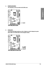
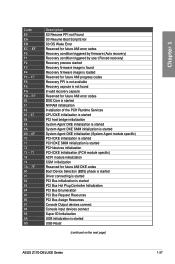
Q-Code LED The Q-Code LED design provides you enable the EZ XMP switch. 6. Chapter 1 5. ASUS Z170-DELUXE Series 1-25 EZ XMP LED (XLED1) This LED lights up when you with a 2-digit error code that displays the system status. Refer to the Q-Code table on the next page for details.
Q-Code LED The Q-Code LED design provides you enable the EZ XMP switch. 6. Chapter 1 5. ASUS Z170-DELUXE Series 1-25 EZ XMP LED (XLED1) This LED lights up when you with a 2-digit error code that displays the system status. Refer to the Q-Code table on the next page for details.
User Guide
Page 45
... Bus Assign Resources Console Output devices connect Console input devices connect Super IO Initialization USB initialization is started USB Reset (continued on the next page) ASUS Z170-DELUXE Series 1-27
... Bus Assign Resources Console Output devices connect Console input devices connect Super IO Initialization USB initialization is started USB Reset (continued on the next page) ASUS Z170-DELUXE Series 1-27
User Guide
Page 47
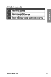
Interrupt controller is in PIC mode. System has transitioned into ACPI mode. Chapter 1 ACPI/ASL Checkpoints (under OS) Code 03 04 05 30 40 AC AA Description System is entering S3 sleep state System is entering S4 sleep state System is entering S5 sleep state System is waking up from the S3 sleep state System is in APIC mode. ASUS Z170-DELUXE Series 1-29 Interrupt controller is waking up from the S4 sleep state System has transitioned into ACPI mode.
Interrupt controller is in PIC mode. System has transitioned into ACPI mode. Chapter 1 ACPI/ASL Checkpoints (under OS) Code 03 04 05 30 40 AC AA Description System is entering S3 sleep state System is entering S4 sleep state System is entering S5 sleep state System is waking up from the S3 sleep state System is in APIC mode. ASUS Z170-DELUXE Series 1-29 Interrupt controller is waking up from the S4 sleep state System has transitioned into ACPI mode.

User Guide
Page 49
ASMedia® Serial ATA 6 Gb/s connectors (7-pin SATA6G_E12) These connectors connect to a slot opening at the back of the system chassis. ASUS Z170-DELUXE Series 1-31 The S/PDIF module is for data drives only. 3. Chapter 1 • ASMedia storage controller can only support AHCI mode. • These SATA ports are ...
ASMedia® Serial ATA 6 Gb/s connectors (7-pin SATA6G_E12) These connectors connect to a slot opening at the back of the system chassis. ASUS Z170-DELUXE Series 1-31 The S/PDIF module is for data drives only. 3. Chapter 1 • ASMedia storage controller can only support AHCI mode. • These SATA ports are ...

User Guide
Page 51
We recommend you to connect a USB 3.0 module for USB-chargeable devices, optimized power efficiency, and backward compatibility with USB 2.0. ASUS Z170-DELUXE Series 1-33 With an installed USB 3.0 module, you can enjoy all the benefits of USB 3.0 including faster data transfer speeds of up to fully use ...
We recommend you to connect a USB 3.0 module for USB-chargeable devices, optimized power efficiency, and backward compatibility with USB 2.0. ASUS Z170-DELUXE Series 1-33 With an installed USB 3.0 module, you can enjoy all the benefits of USB 3.0 including faster data transfer speeds of up to fully use ...

User Guide
Page 53
... fan connector. • The CPU_FAN connector supports the CPU fan of maximum 1A (12 W) fan power. • The CPU_FAN connector and CHA_FAN connectors support the ASUS FAN Xpert 3 feature. • W_PUMP function support depends on water cooling device. • The CPU fan connector detects the type of the connector. • DO... connect the fan cables to Advanced Mode > Monitor > Chassis Fan 1/4 Q-Fan Control items in BIOS. • The chassis fan connectors support DC and PWM modes. ASUS Z170-DELUXE Series 1-35
... fan connector. • The CPU_FAN connector supports the CPU fan of maximum 1A (12 W) fan power. • The CPU_FAN connector and CHA_FAN connectors support the ASUS FAN Xpert 3 feature. • W_PUMP function support depends on water cooling device. • The CPU fan connector detects the type of the connector. • DO... connect the fan cables to Advanced Mode > Monitor > Chassis Fan 1/4 Q-Fan Control items in BIOS. • The chassis fan connectors support DC and PWM modes. ASUS Z170-DELUXE Series 1-35
User Guide
Page 55
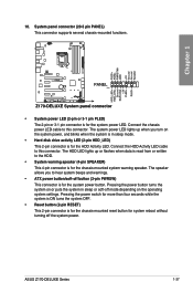
... connector is for the HDD Activity LED. The system power LED lights up or flashes when data is read from or written to this connector. ASUS Z170-DELUXE Series 1-37 Connect the HDD Activity LED cable to hear system beeps and warnings. • ATX power button/soft-off the system power. Pressing the...
... connector is for the HDD Activity LED. The system power LED lights up or flashes when data is read from or written to this connector. ASUS Z170-DELUXE Series 1-37 Connect the HDD Activity LED cable to hear system beeps and warnings. • ATX power button/soft-off the system power. Pressing the...


