

User Guide
Page 16
...start installing the motherboard, and hardware devices on the default riser card that is damaged or missing, contact your motherboard package for buying an ASUS® Z10PH-D16 motherboard! Ensure to protect the pins. If any of the above items is bundled with a cap to remove the cap before using the ...port 10G SFP+ Ethernet Adapter Single port 10G SFP+ Ethernet Adapter • The ASUS PIKE II 3008, PIKE II 3108, and PEM-FDR cards must be installed on the PCI-E X16 slot of Z10PH-D16 ships with the Z10PH-D16 motherboard. • PIKE II 3008/3108 must be installed on on it, check...
...start installing the motherboard, and hardware devices on the default riser card that is damaged or missing, contact your motherboard package for buying an ASUS® Z10PH-D16 motherboard! Ensure to protect the pins. If any of the above items is bundled with a cap to remove the cap before using the ...port 10G SFP+ Ethernet Adapter Single port 10G SFP+ Ethernet Adapter • The ASUS PIKE II 3008, PIKE II 3108, and PEM-FDR cards must be installed on the PCI-E X16 slot of Z10PH-D16 ships with the Z10PH-D16 motherboard. • PIKE II 3008/3108 must be installed on on it, check...

User Guide
Page 17
... processor E5-2600 v3 product family also improve the I/O capabilities and support QPI link speed of up to your problems. Z10PH-D16 合格 xxS2xxxxxxxx 1.4 Special features 1.4.1 Product highlights Latest Processor Technology The motherboard supports Intel Xeon® processor E5-...serial number containing 12 characters xxS2xxxxxxxx shown as the figure below. ASUS Z10PH-D16 1-3 1.3 Serial number label Before requesting support from the ASUS Technical Support team, you must take note of the product, ASUS Technical Support team members can then offer a quicker and satisfying ...
... processor E5-2600 v3 product family also improve the I/O capabilities and support QPI link speed of up to your problems. Z10PH-D16 合格 xxS2xxxxxxxx 1.4 Special features 1.4.1 Product highlights Latest Processor Technology The motherboard supports Intel Xeon® processor E5-...serial number containing 12 characters xxS2xxxxxxxx shown as the figure below. ASUS Z10PH-D16 1-3 1.3 Serial number label Before requesting support from the ASUS Technical Support team, you must take note of the product, ASUS Technical Support team members can then offer a quicker and satisfying ...

User Guide
Page 21
... rear part of the chassis as indicated in the correct orientation. DO NOT overtighten the screws! Place this side towards the rear of the chassis ASUS Z10PH-D16 2-3 Failure to do so can damage the motherboard. 2.2 Motherboard overview Before you install the motherboard, study the configuration of your chassis to ensure that you...
... rear part of the chassis as indicated in the correct orientation. DO NOT overtighten the screws! Place this side towards the rear of the chassis ASUS Z10PH-D16 2-3 Failure to do so can damage the motherboard. 2.2 Motherboard overview Before you install the motherboard, study the configuration of your chassis to ensure that you...
User Guide
Page 23
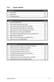
... PANEL1 [White]) Page 2-7 2-12 2-15 Page 2-19 2-20 2-20 2-21 2-21 2-22 2-22 2-23 2-23 2-24 Page 2-28 2-29 2-29 2-30 2-30 2-31 2-32 2-33 ASUS Z10PH-D16 2-5 LAN controller setting (3-pin LAN_SW1, LAN_SW2) 4. CPU sockets 2. Serial General Purpose Input/Output setting (3-pin SGPIO_SEL1) 8. Chassis Intrusion (2-pin INTRUSION1) Internal connectors 1.
... PANEL1 [White]) Page 2-7 2-12 2-15 Page 2-19 2-20 2-20 2-21 2-21 2-22 2-22 2-23 2-23 2-24 Page 2-28 2-29 2-29 2-30 2-30 2-31 2-32 2-33 ASUS Z10PH-D16 2-5 LAN controller setting (3-pin LAN_SW1, LAN_SW2) 4. CPU sockets 2. Serial General Purpose Input/Output setting (3-pin SGPIO_SEL1) 8. Chassis Intrusion (2-pin INTRUSION1) Internal connectors 1.

User Guide
Page 25
Locate the CPU socket on the motherboard. • To prevent damage to the socket pins, do not remove the PnP cap unless you are installing a CPU. • Before installing the CPU, ensure that the socket box is facing toward you and the triangle mark is on the lower-left position. 2.3.1 Installing the CPU To install a CPU: 1. triangle mark ASUS Z10PH-D16 2-7
Locate the CPU socket on the motherboard. • To prevent damage to the socket pins, do not remove the PnP cap unless you are installing a CPU. • Before installing the CPU, ensure that the socket box is facing toward you and the triangle mark is on the lower-left position. 2.3.1 Installing the CPU To install a CPU: 1. triangle mark ASUS Z10PH-D16 2-7

User Guide
Page 27
... bending the CPU pins on the socket box. 8. Push down the left load lever under the retention tab (J). ASUS Z10PH-D16 2-9 Triangle mark 7. DO NOT force the CPU into the slot. Keep the PnP cap. ASUS will process Return Merchandise Authorization (RMA) requests only if the motherboard comes with the PnP cap on top...
... bending the CPU pins on the socket box. 8. Push down the left load lever under the retention tab (J). ASUS Z10PH-D16 2-9 Triangle mark 7. DO NOT force the CPU into the slot. Keep the PnP cap. ASUS will process Return Merchandise Authorization (RMA) requests only if the motherboard comes with the PnP cap on top...

User Guide
Page 29
Twist each of the installed CPU, ensuring that the four fasteners match the holes on the motherboard. 2. A B B A ASUS Z10PH-D16 2-11 When the four screws are attached, tighten them one by one to the motherboard. Place the heatsink on top of the four screws with a Philips (cross) screwdriver just enough to attach the heatsink to completely secure the heatsink. Tighten the four heatsink screws in a diagonal sequence. 2.3.2 Installing the CPU heatsink To install the CPU heatsink: 1.
Twist each of the installed CPU, ensuring that the four fasteners match the holes on the motherboard. 2. A B B A ASUS Z10PH-D16 2-11 When the four screws are attached, tighten them one by one to the motherboard. Place the heatsink on top of the four screws with a Philips (cross) screwdriver just enough to attach the heatsink to completely secure the heatsink. Tighten the four heatsink screws in a diagonal sequence. 2.3.2 Installing the CPU heatsink To install the CPU heatsink: 1.

User Guide
Page 31
... (CPU2) A2 A1 B2 B1 C2 C1 D2 D1 E2 E1 F2 F1 G2 G1 H2 H1 2 DIMMs P P 4 DIMMs P P P P 8 DIMMs P P P P P P P P 12 DIMMs P P P P P PPPPP P P 16 DIMMs P P P P P P P P P P P P P P P P ASUS Z10PH-D16 2-13 Single CPU configuration (must be installed on CPU1) DIMM A2 A1 B2 B1 C2 C1 D2 D1 1 DIMM P 1 DIMM P 2 DIMMs P P 4 DIMMs P P P P 8 DIMMs P P P P P P P P Dual CPU...
... (CPU2) A2 A1 B2 B1 C2 C1 D2 D1 E2 E1 F2 F1 G2 G1 H2 H1 2 DIMMs P P 4 DIMMs P P P P 8 DIMMs P P P P P P P P 12 DIMMs P P P P P PPPPP P P 16 DIMMs P P P P P P P P P P P P P P P P ASUS Z10PH-D16 2-13 Single CPU configuration (must be installed on CPU1) DIMM A2 A1 B2 B1 C2 C1 D2 D1 1 DIMM P 1 DIMM P 2 DIMMs P P 4 DIMMs P P P P 8 DIMMs P P P P P P P P Dual CPU...

User Guide
Page 33
... the system cover if your motherboard is seated firmly in a chassis. 2. The slot can switch to the onboard PCI-E slot. Riser card PCI-E x24 slot ASUS Z10PH-D16 2-15 Align and insert the riser card into the PCI-E x24 slot. Locate the PCI-E x24 slot in the motherboard. 3. 2.5 Expansion slots The following subsections...
... the system cover if your motherboard is seated firmly in a chassis. 2. The slot can switch to the onboard PCI-E slot. Riser card PCI-E x24 slot ASUS Z10PH-D16 2-15 Align and insert the riser card into the PCI-E x24 slot. Locate the PCI-E x24 slot in the motherboard. 3. 2.5 Expansion slots The following subsections...

User Guide
Page 35
4. The expansion card fits in one orientation only. Align and insert the riser card and expansion card assembly into the PCI-E slot on the motherboard. If it does not fit, try reversing it. 5. Replace the system cover. riser card and expansion card assembly PCI-E x24 slot ASUS Z10PH-D16 2-17
4. The expansion card fits in one orientation only. Align and insert the riser card and expansion card assembly into the PCI-E slot on the motherboard. If it does not fit, try reversing it. 5. Replace the system cover. riser card and expansion card assembly PCI-E x24 slot ASUS Z10PH-D16 2-17

User Guide
Page 37
..., never remove the cap on pins 2-3 for about 5-10 seconds, then move the jumper again to pins 2-3. Keep the cap on CLRTC jumper default position. ASUS Z10PH-D16 2-19
..., never remove the cap on pins 2-3 for about 5-10 seconds, then move the jumper again to pins 2-3. Keep the cap on CLRTC jumper default position. ASUS Z10PH-D16 2-19

User Guide
Page 39
... over pins 1-2 to use when you to select the RAID configuration utility to quickly recover the Intel Management Engine (ME) firmware when it becomes corrupted. ASUS Z10PH-D16 2-21 ME firmware force recovery setting (3-pin ME_RCVR1) This jumper allows you to use the Intel® Rapid Storage Technology enterprise SATA Option ROM Utility...
... over pins 1-2 to use when you to select the RAID configuration utility to quickly recover the Intel Management Engine (ME) firmware when it becomes corrupted. ASUS Z10PH-D16 2-21 ME firmware force recovery setting (3-pin ME_RCVR1) This jumper allows you to use the Intel® Rapid Storage Technology enterprise SATA Option ROM Utility...

User Guide
Page 41
ASUS Z10PH-D16 2-23 PMBus 1.2 PSU select jumper (3-pin SMART_PSU1) This jumper allows you to enable or disable the ASMB8. 9. Set to pins 1-2 for PMBus, set to select PSU PMBus version. 8. BMC Setting (3-pin BMC_EN) This jumper allows you to pins 2-3 for others.
ASUS Z10PH-D16 2-23 PMBus 1.2 PSU select jumper (3-pin SMART_PSU1) This jumper allows you to enable or disable the ASMB8. 9. Set to pins 1-2 for PMBus, set to select PSU PMBus version. 8. BMC Setting (3-pin BMC_EN) This jumper allows you to pins 2-3 for others.

User Guide
Page 43
... Status Description OFF No link GREEN Linked BLINKING Data activity Status OFF ORANGE GREEN Speed LED Description 10 Mbps connection 100 Mbps connection 1 Gbps connection ASUS Z10PH-D16 2-25 RJ-45 port for a VGA monitor or other VGA-compatible devices. 4. Video Graphics Adapter port. The Q-Code LED provides a 2-digit display that shows the...
... Status Description OFF No link GREEN Linked BLINKING Data activity Status OFF ORANGE GREEN Speed LED Description 10 Mbps connection 100 Mbps connection 1 Gbps connection ASUS Z10PH-D16 2-25 RJ-45 port for a VGA monitor or other VGA-compatible devices. 4. Video Graphics Adapter port. The Q-Code LED provides a 2-digit display that shows the...

User Guide
Page 47
...fan connectors (4-pin FRNT_FAN1-4) The fan connectors support cooling fans of 350 mA-740 mA (8.88 W max.) or a total of the system chassis. ASUS Z10PH-D16 2-29 USB connector (5-1 pin USB3; These USB connectors comply with USB 2.0 specification that the black wire of each cable matches the ground pin of... cables to connectors USB3, then install the modules to the fan connectors on the fan connectors! • All fans feature the ASUS Smart Fan technology. Insufficient air flow inside the system may damage the motherboard components. • These are for USB 2.0 ports. 2.
...fan connectors (4-pin FRNT_FAN1-4) The fan connectors support cooling fans of 350 mA-740 mA (8.88 W max.) or a total of the system chassis. ASUS Z10PH-D16 2-29 USB connector (5-1 pin USB3; These USB connectors comply with USB 2.0 specification that the black wire of each cable matches the ground pin of... cables to connectors USB3, then install the modules to the fan connectors on the fan connectors! • All fans feature the ASUS Smart Fan technology. Insufficient air flow inside the system may damage the motherboard components. • These are for USB 2.0 ports. 2.

User Guide
Page 49
M.2 (NGFF) connector (NGFF1) This connector allows you to install an M.2 device. • This connector supports type 2242 devices on storage card using a SATA cable. - For SATA Interface: Connect the FP_SATA7 (light gray) port to any of the onboard SATA ports (SATA 1-6) or any SATA port from the add-on both SATA and PCI-E interface. • Please refer to support this function. For PCIE Interface: You need to install a second CPU (on CPU2) to the following guidelines in installing an M.2 device: - The M.2 (NGFF) device is purchased separately ASUS Z10PH-D16 2-31 6.
M.2 (NGFF) connector (NGFF1) This connector allows you to install an M.2 device. • This connector supports type 2242 devices on storage card using a SATA cable. - For SATA Interface: Connect the FP_SATA7 (light gray) port to any of the onboard SATA ports (SATA 1-6) or any SATA port from the add-on both SATA and PCI-E interface. • Please refer to support this function. For PCIE Interface: You need to install a second CPU (on CPU2) to the following guidelines in installing an M.2 device: - The M.2 (NGFF) device is purchased separately ASUS Z10PH-D16 2-31 6.

User Guide
Page 51
... more than four seconds while the system is in sleep or soft-off the system power. Connect the HDD Activity LED cable to the HDD. ASUS Z10PH-D16 2-33 The IDE LED lights up when the Locator button is for the HDD Activity LED. Pressing the power switch for the Locator button on...
... more than four seconds while the system is in sleep or soft-off the system power. Connect the HDD Activity LED cable to the HDD. ASUS Z10PH-D16 2-33 The IDE LED lights up when the Locator button is for the HDD Activity LED. Pressing the power switch for the Locator button on...

User Guide
Page 53
CATT ERR LED (CATTERR1) The CATT ERR LED indicates that the system is a reminder that you should shut down the system and unplug the power cable before removing or plugging in soft-off mode. 3. ASUS Z10PH-D16 2-35 The illustration below shows the location of the onboard LED. 4. Standby Power LED (SBPWR1) The motherboard comes with a standby power LED. The green LED lights up to indicate that the system has experienced a fatal or catastrophic error and cannot continue to operate. This is ON, in sleep mode, or in any motherboard component.
CATT ERR LED (CATTERR1) The CATT ERR LED indicates that the system is a reminder that you should shut down the system and unplug the power cable before removing or plugging in soft-off mode. 3. ASUS Z10PH-D16 2-35 The illustration below shows the location of the onboard LED. 4. Standby Power LED (SBPWR1) The motherboard comes with a standby power LED. The green LED lights up to indicate that the system has experienced a fatal or catastrophic error and cannot continue to operate. This is ON, in sleep mode, or in any motherboard component.

User Guide
Page 55
The Location LED helps visually locate and quickly identify the server in error on the server is pressed or when triggered by a system management software. 7. ASUS Z10PH-D16 2-37 Location LED (LOCLED1) This onboard LED lights up when the Location button on a server rack.
The Location LED helps visually locate and quickly identify the server in error on the server is pressed or when triggered by a system management software. 7. ASUS Z10PH-D16 2-37 Location LED (LOCLED1) This onboard LED lights up when the Location button on a server rack.

User Guide
Page 57
FP Serial ATA connectors (7-pin FP_SATA5-6 [Light blue], FP_SATA7 [light gray]) These connectors switches to any of the onboard SATA ports (SATA1-6) or from any SATA port from the add-on storage cards. 2. Golden Finger Power connector Refer to the following illustration for system design when you connect the FP_SATA5-7 to Golden finger for the golden finger's power pin definition. 3. ASUS Z10PH-D16 2-39
FP Serial ATA connectors (7-pin FP_SATA5-6 [Light blue], FP_SATA7 [light gray]) These connectors switches to any of the onboard SATA ports (SATA1-6) or from any SATA port from the add-on storage cards. 2. Golden Finger Power connector Refer to the following illustration for system design when you connect the FP_SATA5-7 to Golden finger for the golden finger's power pin definition. 3. ASUS Z10PH-D16 2-39

